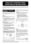
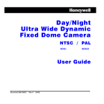
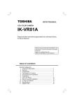
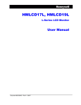
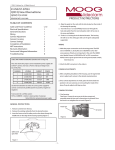
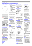
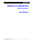
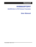
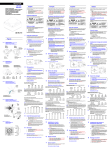
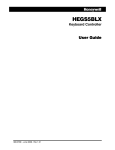
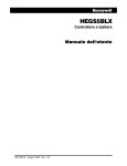
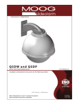
1
HD16
CCTV Camera
User Guide
Document 900.0345 – Rev 1.02 – 03/07
Revisions
Issue
Date
Revisions
1.00
03/06
New document based on 900.0184 rev 4.00.
1.01
05/06
Amended Figure 11 to show 4 DIP switches.
1.02
03/07
Removed monochrome models, updated specs.
2
Warnings
Installation and servicing should be performed only by qualified and experienced
technicians to conform to all local codes and to maintain your warranty.
WARNING! The use of CSA Certified/UL Listed Class 2
power adapters is required to ensure
compliance with electrical safety standards.
Explanation of Graphical Symbols
CAUTION
RISK OF ELECTRIC
SHOCK
DO NOT OPEN
CAUTION: TO REDUCE THE RISK OF ELECTRIC
SHOCK, DO NOT REMOVE THE COVER.
NO USER-SERVICEABLE PARTS INSIDE
REFER SERVICING TO QUALIFIED
SERVICE PERSONNEL
Document 900.0345 Rev 1.02
03/07
THIS SYMBOL INDICATES THAT
DANGEROUS VOLTAGE
CONSTITUTING A RISK OF
ELECTRIC SHOCK IS PRESENT
WITHIN THE UNIT.
THIS SYMBOL INDICATES THAT
IMPORTANT OPERATING AND
MAINTENANCE INSTRUCTIONS
ACCOMPANY THIS UNIT.
3
FCC Compliance Statement
Information to the User: This equipment has been tested and found to
comply with the limits for a Class A digital device. Pursuant to Part 15 of the
FCC Rules, these limits are designed to provide reasonable protection
against harmful interference when the equipment is operated in a
commercial environment. This equipment generates, uses, and can radiate
radio frequency energy and, if not installed and used in accordance with the
instruction manual, may cause harmful interference to radio
communications. Operation of this equipment in a residential area is likely to
cause harmful interference in which case the user will be required to correct
the interference at his own expense.
Caution
Changes or modifications not expressly approved by the party
responsible for compliance could void the user’s authority to
operate the equipment.
This Class A digital apparatus complies with Canadian ICES-003.
Cet appareil numérique de la Classe A est conforme à norme NMB-003 du
Canada.
4
Contents
Contents . . . . . . . . . . . . . . . . . . . . . . . . . . . . . . . . . . . . . . . . . . . . . . . . 5
Overview. . . . . . . . . . . . . . . . . . . . . . . . . . . . . . . . . . . . . . . . . . . . . . . . 6
Before You Begin . . . . . . . . . . . . . . . . . . . . . . . . . . . . . . . . . . . . . . . . . 6
Unpack Everything . . . . . . . . . . . . . . . . . . . . . . . . . . . . . . . . . . . . . . .6
Equipment Required . . . . . . . . . . . . . . . . . . . . . . . . . . . . . . . . . . . . . .6
Installation . . . . . . . . . . . . . . . . . . . . . . . . . . . . . . . . . . . . . . . . . . . . . . 7
Overview of Assembly Procedure . . . . . . . . . . . . . . . . . . . . . . . . . . . . . .7
Mount the HD16 . . . . . . . . . . . . . . . . . . . . . . . . . . . . . . . . . . . . . . . . . . . .8
Connect the Power Cable . . . . . . . . . . . . . . . . . . . . . . . . . . . . . . . . . . . .9
Install the Camera Assembly . . . . . . . . . . . . . . . . . . . . . . . . . . . . . . . . .10
Adjust the Camera . . . . . . . . . . . . . . . . . . . . . . . . . . . . . . . . . . . . . . . . .10
DIP Switch Functions (Color and TDN Cameras) . . . . . . . . . . . . . . .13
Adjustment Method (Color and TDN Cameras) . . . . . . . . . . . . . . . .13
White Balance Adjustment Method (Color and TDN Cameras) . . . .14
Manually Setting Shutter Speed (Color and TDN Cameras) . . . . . .14
DIP Switch Functions (WDR Cameras) . . . . . . . . . . . . . . . . . . . . . . .15
Adjustment Method (WDR Cameras) . . . . . . . . . . . . . . . . . . . . . . . .15
Adjust the Line Lock (Vertical Phase) For External Sync Reference 16
Adjust the Backlight Compensation . . . . . . . . . . . . . . . . . . . . . . . . .16
Secure the Camera and Dome Enclosure . . . . . . . . . . . . . . . . . . . . . . .16
Routine Maintenance . . . . . . . . . . . . . . . . . . . . . . . . . . . . . . . . . . . . . . .17
Dome Replacement . . . . . . . . . . . . . . . . . . . . . . . . . . . . . . . . . . . . . . . .17
Solving Common Technical Issues . . . . . . . . . . . . . . . . . . . . . . . . . 18
Service19
Specifications . . . . . . . . . . . . . . . . . . . . . . . . . . . . . . . . . . . . . . . . . . 20
Cable Guidelines . . . . . . . . . . . . . . . . . . . . . . . . . . . . . . . . . . . . . . . . 22
HD16 Model Numbers . . . . . . . . . . . . . . . . . . . . . . . . . . . . . . . . . . . . 23
Document 900.0345 Rev 1.02
03/07
5
Overview
The HD16 CCTV Camera can be flush or surface mounted to a wall or ceiling. The
HD16 features a high-impact plastic enclosure and polycarbonate dome that has
an adjustable dome insert to conceal camera components without compromising
light sensitivity or picture quality. The HD16 accommodates a 5-50 mm varifocal
auto-iris lens.
Before You Begin
Please read this guide carefully before you
install this HD16 CCTV Camera.
Keep this guide for future reference.
Unpack Everything
Check that the items received match those listed on the order form and packing
slip. The HD16 packing box should include, in addition to this User Guide:
• One fully assembled HD16 Camera
• One HD16 hardware kit
• One Product Warranty card
If any parts are missing or damaged, please contact the dealer you purchased
the camera from, or call Honeywell Customer Service. See “Service” on page 19.
Equipment Required
You will require the following tools to complete the installation:
• Phillips screwdriver.
• Side-cutters.
• Mounting screws. Use mounting screws appropriate to your installation.
6
Installation
The HD16 Camera is designed to be flush or surface mounted on a wall or
ceiling. It is weather sealed for indoor or outdoor locations.
Overview of Assembly Procedure
Task
See section
1. Mount the HD16 to a ceiling or wall.
See “Mount the HD16” on page 8.
2. Connect the cable to the camera
board.
See “Connect the Power Cable” on
page 9.
3. Secure the gimbal into the HD16
base.
See “Install the Camera Assembly”
on page 10.
4. Adjust the camera settings.
See “Adjust the Camera” on page 10.
5. Secure the cover.
See “Secure the Camera and Dome
Enclosure” on page 16.
Figure 1
Installation Components
Skirt (optional)
HD16 base
Gimbal
HD16 dome cover
Document 900.0345 Rev 1.02
03/07
7
Mount the HD16
Follow Figure 2 to mount the HD16 flush to a ceiling or wall.
Figure 2
Flush Mount Installation
HD16 base
Mounting screws (not
supplied)
Follow Figure 3 to surface mount the HD16 to a wall or ceiling.
Figure 3
Surface Mount Installation
Skirt
Mounting screws (not
supplied)
#8-32 x 3/8 inch machine
screws (x4)
8
Connect the Power Cable
1.
Follow Figure 4 for the wiring connection.
Figure 4
Wiring
Coaxial Cables
UTP Cables
Video: Unshielded
Twisted Pair wire
Video: female BNC
Power
red +
connect to red +
2.
black connect to ground
Power: 2.1 mm
male jack center pin
Connect the power/video cable from the gimbal assembly to the camera
board (see Figure 5).
Note
For secure installations, surface-mounted cables should be
protected by plastic or metal cable covers.
Figure 5
Power Cable Connection
Gimbal assembly
Power/video cable
Camera board
Document 900.0345 Rev 1.02
03/07
9
Install the Camera Assembly
To install the camera assembly into the HD16 base:
1. Remove one of the three thumb nuts from the camera chassis (see Figure 6).
Loosen the other two thumb nuts.
2. Slide the gimbal ring under the two loosened thumb nuts.
3. Adjust the camera position. See “Adjust the Camera” on page 10.
4. Replace the thumb nut you previously removed in step 1.
5. Tighten all three thumb nuts to secure the camera assembly.
Make sure that the camera DIP switches are on the top of the lens mount
when the HD16 is mounted on the wall or ceiling.
Figure 6
Camera Assembly
Loosen thumb
nuts (x2)
Remove thumb nut
Gimbal ring
Gimbal chassis
Adjust the Camera
To adjust the HD16 Camera:
1. Apply 11-16 VDC or 24 VAC power to the camera and monitor the video
signal.
2. Loosen as many screws and thumb nuts that lock the gimbal assembly in
place as necessary to adjust the camera position (see Figure 6).
3. Adjust the camera carrier to the desired view by moving the gimbal in the V
groove (see Figure 7).
10
Figure 7
Recommended Camera Positions
Recommended
camera positions
Use these alternate
positions when your
desired field of view
(FOV) is a steep angle
or parallel to a wall or
ceiling.
FOV
Figure 8 shows how to use the thumb nuts and screws to adjust the gimbal.
Figure 8
Gimbal Adjustment
Tilt rotation
C
A
Pan rotation
V groove
B
C
A
Legend
A = Pan rotation
B = Horizontal rotation
C = Tilt rotation
Document 900.0345 Rev 1.02
03/07
B
Horizontal rotation
B
11
4.
5.
6.
7.
8.
Tighten the screws and thumb nuts to lock the gimbal assembly in place.
Focus the lens:
a.
Place the dome as shown in Figure 9.
b.
Adjust the focal length using the top locking screw. See Figure 10 for
color cameras or Figure 11 for monochrome cameras.
c.
Adjust the focus using the bottom locking screw (closest to the camera
board). See Figure 10 for color cameras or Figure 11 for monochrome
cameras.
To adjust the camera direction, view angle and focus, connect the service
monitor cable (supplied) to the video monitor output (see Figure 10 for color
cameras and Figure 11 for monochrome cameras).
Rotate the dome and place it over the base so that the security screws are
lined up with the screw holes on the base.
Check the picture. If the focus is clear, go to step 9. If the focus is not clear,
repeat step 5 and step 6 until you are satisfied with the picture clarity.
Figure 9
Lens Focus and Field of View Adjustment
Vari-focal Auto Iris Configuration (Color Cameras)
To adjust the focal length and focus of the lens, see Figure 10. Color
cameras have a potentiometer on top of the board to regulate the Auto Iris
lens.
9.
Set the DIP switches. See the following sections for the DIP switch functions
and adjustment methods.
12
DIP Switch Functions (Color and TDN Cameras)
Figure 10
Color Camera Switch Settings (Vari-focal Auto Iris Lens
Shown)
You may find it helpful to
use the Allen key (supplied) to
access the DIP switches.
Note
GAMMA
AE
FLON
BLC
IRIS
NU*
AGC MAX
AWB1
AWB2
AWB3
* N/U = Not used.
Leave in Off position.
10
9
8
7
6
5
4
3
2
Push lock
Video
monitor
output
1
Top locking
screw adjusts
focal length.
Bottom locking
screw adjusts
focus.
Factory (default) settings
Vari-focal Auto Iris
10
DC Iris
adjust
Line-lock phase
adjustment pot
9
8
7
= ON (up)
6
5
4
3
2
1
= OFF (down)
Adjustment Method (Color and TDN Cameras)
Switch Function
no.
Off
On
10
GAMMA
Off (0.45)
On (1.0)
9
AE (Automatic
Exposure)
Off
On (see Manually Setting Shutter
Speed (Color and TDN Cameras))
8
FLON (Flicker Less) Off
On
7
BLC (Backlight
Compensation)
Off
On (Center window)
6
IRIS Control
Electronic IRIS Auto IRIS
5
Not used
Not used
Not used
4
AGC
4 dB
26 dB
Document 900.0345 Rev 1.02
03/07
13
White Balance Adjustment Method (Color and TDN
Cameras)
Symbol
SW3/AWB1
SW2AWB2
SW1AWB3
AWB
Off
Off
Off
ATW
Off
On
Off
Push lock
Off
On
On *
Indoor (3200° K)
On
Off
On
Outdoor (6500° K)
On
On
On
* To manually set Push lock feature: place a white background in front of camera
and press “Push lock” switch.
Manually Setting Shutter Speed (Color and TDN
Cameras)
To manually set the shutter speed, turn switch #9 to the ON position; then set
switch #6, #7, and #8 for the desired shutter speed (see Figure 10).
Shutter
speed(s)
SW6
IRIS
SW7
BLC
SW8
FLON
SW9
AE
1/50 (PAL)
1/60 (NTSC)
Off
On
Off
On
1/100 (PAL)
1/120 (NTSC)
Off
On
On
On
1/250
Off
Off
Off
On
1/500
Off
Off
On
On
1/1000
On
On
Off
On
1/2000
On
On
On
On
1/4000
On
Off
Off
On
1/10000
On
Off
On
On
Note
Caution
FLON, BLC, and IRIS can be set when switch #9 is set to the OFF
position.
Before you adjust the shutter speed, it is important that you
understand how the settings can affect the scene detail.
14
DIP Switch Functions (WDR Cameras)
* Not used.
Leave in ON
position.
WDR Camera Switch Settings
Line-lock
adjustment
Note You may find it helpful
to use the Allen key (supplied)
to access the DIP switches.
AGC
N/U*
WDR
AWB/ATW
Figure 11
Factory (default) settings
Auto Iris level
adjustment. If
necessary, turn
clockwise to
increase brightness
level.
Note
= ON (up)
= OFF (down)
Video monitor
output
The Wide Dynamic Range camera has been designed for the best
wide dynamic performance and can only be used with Vari-focal
Auto Iris lens.
Adjustment Method (WDR Cameras)
Switch
no.
Function
Off
On
1
AGC
Off
On
2
Not used
Off
On*
3
WDR (Wide Dynamic Range)
Off
On
4
AWB/ATW
ATW
AWB
* Leave switch #2 in ON position to ensure the camera functions
properly.
Document 900.0345 Rev 1.02
03/07
15
Adjust the Line Lock (Vertical Phase) For External Sync
Reference
Phase adjustment may be necessary in multiple camera installations to prevent
picture roll when switching between cameras. To adjust the vertical phase while
switching between two cameras, turn the line lock adjustment pot on one camera
until there is no vertical roll. See Figure 10 for color cameras and Figure 11 for
monochrome cameras. The wide dynamic range (WDR) cameras use line lock
adjustment buttons to adjust the vertical phase (see Figure 11).
Note
If the phase cannot be adjusted to prevent picture roll, reverse the
line-lock input polarity.
Adjust the Backlight Compensation
The backlight compensation (BLC) adjusts the electronic shutter speed of the
camera based on the light levels in specific areas of the scene. This adjustment
provides better image quality for scenes that are unevenly lit.
To adjust the BLC, set the BLC switch to ON (see Figure 10 for color cameras and
Figure 11 for monochrome cameras). Center window weighted.
Secure the Camera and Dome Enclosure
To secure the camera and dome enclosure:
1. Ensure that the gimbal is locked in place (see Figure 6).
2. Rotate the dome enclosure until the #8-32 security screws line up with the
base, then secure it to the base (see Figure 12).
Figure 12
Enclosure Cover Installation
HD16 base
Thumb nuts
(x3)
#8-32 security screws
(x4)
Dome enclosure
16
Routine Maintenance
Use regular liquid cleaners to remove most dirt and grime from the HD16
enclosure.
Caution
Do not use harsh or abrasive cleaners which can scratch the
polycarbonate dome and reduce visibility from the camera.
Dome Replacement
If the polycarbonate dome is damaged or scratched beyond use, contact your
distributor or salesperson to order a dome replacement. To replace the HD16
dome:
1. Use the security hex key (supplied) to loosen the #8-32 security screws
securing the HD16 lid to the base.
2. Use a Phillips screwdriver to remove the #6 x 1/4 inch Hi-lo tapping screws
that attach the dome retainer plate to the front cover.
3. Remove the damaged dome and replace it with the new dome.
4. Use a Phillips screwdriver to attach the dome retainer plate to the HD16 front
plate with the screws you removed in step 2.
5. Use the security hex key to tighten the security screws that secure the HD16
lid to the base.
Figure 13
Dome replacement
#8-32 security screws (x4)
Front cover
Polycarbonate dome
Dome turret
Gasket
Retainer plate
#6 x 1/4 inch Hi-lo tapping screws (x4)
Document 900.0345 Rev 1.02
03/07
17
Solving Common Technical Issues
No video
❐
Check that the power supply voltage is within the operating
specifications for your camera model (see Specifications) for
details).
❐
Connect a video monitor directly to the HD16 video output cable to
eliminate video problems that could be caused by other
equipment such as video switches.
❐
Check the video connections to the monitor or CCTV system.
❐
Check for a loose connection at the video camera.
Fuzzy video
❐
Check the video ground connections.
❐
Check for ground loops.
Call Honeywell Customer Service for additional assistance (see Service for
contact numbers).
18
Service
Subject to the terms and conditions listed on the Product Warranty Card, during
the warranty period Honeywell will repair or replace, at its sole option, free of
charge, any defective products returned prepaid.
In the event you have a problem with any Honeywell product, please call
Customer Service for assistance or to request a Return Merchandise
Authorization (RMA) number.
In the U.S.A. and Canada, call 1.800.796.2288.
Be sure to have the model number, serial number, and the nature of the problem
available for the technical service representative.
Prior authorization must be obtained for all returns, exchanges, or credits. Items
shipped to Honeywell without a clearly identified Return Merchandise
Authorization (RMA) number may be refused.
Document 900.0345 Rev 1.02
03/07
19
Specifications
Video specifications
High RES
Standard RES
Pickup device:
1/3 in. CCD
Electronic iris:
1/60 to 1/100,000 second
Surge protection:
1.5 kW transient
Video output impedance:
1 Vp-p @ 75 Ohms
Video signal:
Color
Resolution:
Standard NTSC
High RES
Standard RES
Color, True Day/Night
480 TV lines
350 TV lines
Wide Dynamic, Wide
Dynamic True Day/Night
480 TV lines
n/a
Signal to noise ratio
(monochrome and color):
Better than 51 dB
Dynamic range (Wide
Dynamic camera only):
Better than 52 dB
Light sensitivity:
Color
0.7 lux @ F1.7
True Day/Night
0.3 lux @ F1.7
0.6 lux @ F1.7
0.2 lux @ F1.7
Wide Dynamic
1.0 lux @ F1.7
Wide Dynamic True Day/Night
0.4 lux @ F1.7
White Balance:
Color, True Day/Night
BLC
Lens Type
Angle of View
AWB/ATW/Indoor (3200°K), Outdoor (6500°K), Push Lock
Center window weighted on/off, switchable
5 to 50 mm (F1.7) Vari-focal Auto Iris CS Mount
Tele: 6.9°(D), 5.5°(H), 4.1°(V)
Wide: 63°(D), 48°(H), 35°(V)
Power requirements
Input voltage:
Input range:
24 VAC/12 VDC
17 to 28 VAC, 11 to 16 VDC
Power consumption:
Color
3.5 W (max)
True Day/Night
3.5 W (max)
Wide Dynamic, Wide
Dynamic True Day/Night
4.5 W (max)
20
Operating environment
Temperature:
Operating
-13°F to 122°F (-25°C to 50°C)
Storage
-31°F to 140°F (-35°C to 50°C)
Humidity:
0 to 95% RH non-condensing
Size and weight
Dimensions
Size
7.5 in. x 5.3 in. (191 mm x 134.5 mm
2.0 lb (0.9 kg)
Regulatory
Emissions
Immunity
Safety
Note
FCC, CE (EN55013)
CE (EN50130-4)
EU: 73/23/EEC LVD, UL2044
Specifications apply to all camera models, unless noted otherwise.
Document 900.0345 Rev 1.02
03/07
21
Cable Guidelines
Power supply cable maximum length (feet/meters)
Wire gauge
Total
load
Power
supply
24 AWG
22 AWG
18 AWG
16 AWG
Cameras with AC/DC power supplies
3.5 W
15 VDC
180/55
290/88
730/220
1170/352
3.5 W
24 VAC
470/143
760/232
1926/587
3065/934
Note
Calculations are based on an unregulated linear power supply which would
be the worst case. Using a regulated or switching power supply can increase
the cable distance. We recommend using a CSA Certified/UL listed Class 2
power adapter to ensure compliance with electrical safety standards.
Video cable maximum length (feet/meters)
Cable type
RG-59
RG-6
RG-11
Wire gauge
23 AWG*
18 AWG*
14 AWG*
750/229
1500/457
2000/610
Maximum length (feet/meters)
* Copper clad steel core, 95% braided shield
We recommend these NVT video transceivers (sold separately by NVT Inc.):
•
•
•
NV-212A (500 ft/152 m—26 Ω)**
NV-213A/A-M (1000 ft/305 m—52 Ω)**
NV-652R, NV-862R or NV-1662R (3000 ft/914 m—163 Ω)**
** Distances have been calculated using 24 AWG Twisted Pair wire.
Note
We recommend that you measure the wire distance to ensure the capability
of the twisted pair product is not exceeded. Use an ohmmeter to measure wire
resistance by shorting the two conductors together at the far end, then
measure the loop resistance out and back. Compare to the table below.
Maximum length (feet/meters)
AWG
250/76
500/152
1000/305
1500/457
2000/610
18
3Ω
6Ω
13 Ω
19 Ω
26 Ω
20
5Ω
10 Ω
20 Ω
30 Ω
40 Ω
22
8Ω
17 Ω
33 Ω
48 Ω
66 Ω
24
13 Ω
26 Ω
52 Ω
78 Ω
108 Ω
Note
Use point-to-point Unshielded Twisted Pair wire only.
22
HD16 Model Numbers
HD16T-DW-480
Typical HD16 model number
Camera Resolution
350
480
Standard Resolution, 350 TVL
High Resolution, 480 TVL
Camera Options
C
D
W
DW
Color
True Day/Night
Wide Dynamic
Wide Dynamic True Day/Night
Interface
C
T
Document 900.0345 Rev 1.02
03/07
Coaxial
UTP (Twisted Pair)
23
Honeywell Video Systems (Head Office)
2700 Blankenbaker Pkwy, Suite 150
Louisville, KY 40299, USA
www.honeywellvideo.com
℡ +1.800.796.2288
Honeywell Video Systems Northern Europe
Netwerk 121
1446 WV Purmerend, The Netherlands
www.SecurityHouse.nl
℡ +31.299.410.200
Honeywell Security Australia Pty Ltd.
Unit 5, Riverside Centre, 24-28 River Road West
Parramatta, NSW 2150, Australia
www.ademco.com.au
℡ +61.2.8837.9300
Honeywell Video Systems UK Ltd.
Aston Fields Road, Whitehouse Ind Est
Runcorn, Cheshire, WA7 3DL, UK
www.honeywellvideo.com
℡ +0844 8000 235
Honeywell Security Asia Pacific
33/F Tower A, City Center, 100 Zun Yi Road
Shanghai 200051, China
www.security.honeywell.com/cn
℡ +86 21.2527.4568
Honeywell Security South Africa
Unit 6 Galaxy Park, 17 Galaxy Avenue
Linbro Park, P.O. Box 59904
2100 Kengray, Johannesburg, South Africa
www.honeywell.co.za
℡ +27.11.574.2500
Honeywell Security Asia
Flat A, 16/F, CDW Building, 388 Castle Peak Road
Tsuen Wan, N.T., Hong Kong
www.security.honeywell.com/hk
℡ +852.2405.2323
Honeywell Security France
Parc Gutenberg, 8, Voie La Cardon
91120, Palaiseau, France
www.honeywell.com/security/fr
℡ +33.01.64.53.80.40
Honeywell Security Italia SpA
Via Treviso 2 / 4
31020 San Vendemiano
Treviso, Italy
www.honeywell.com/security/it
℡ +39.04.38.36.51
Honeywell Security España
Mijancas 1. 3a Planta
P. Ind. Las Mercedes
28022 Madrid, Spain
www.security.honeywell.com/es
℡ +34.902.667.800
Honeywell Security Deutschland
Johannes-Mauthe-Straße 14
D-72458 Albstadt, Germany
www.honeywell.com/security/de
℡ +49.74 31.8 01.0
Honeywell Security Poland
Chmielewskiego 22a, 70-028
Szczecin, Polska
www.ultrak.pl
℡ +48.91.485.40.60
Honeywell Security Czech Republic
Havránkova 33, Brno
Dolní Heršpice, 619 00, Czech Republic
www.olympo.cz
℡ +420.543.558.111
Honeywell Security Slovakia Republic
Vajnorská 142, 83104 Bratislava
Slovakia
www.olympo.sk
℡ +421.2.444.54.660
www.honeywellvideo.com
+1.800.796.CCTV (North America only)
[email protected]
Document 900.0345 – Rev 1.02 – 03/07
© 2007 Honeywell International Inc. All rights reserved. No part of this publication may be
reproduced by any means without written permission from Honeywell Video Systems. The
information in this publication is believed to be accurate in all respects. However, Honeywell Video
Systems cannot assume responsibility for any consequences resulting from the use thereof. The
information contained herein is subject to change without notice. Revisions or new editions to this
publication may be issued to incorporate such changes.