1
3 – Installation (continued)
3-4 Installation Across Aisle
Note: Follow the instructions in this section only if the SRCABLELADDER accessory will be installed across an aisle. If the SRCABLELADDER
accessory will be installed within a row of enclosures, follow the instructions in Section 3-5 Installation Within Row instead.
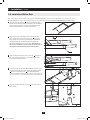
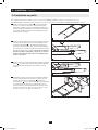
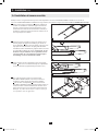
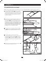
1 Insert four assembly brackets A into the ends of the ladder. The
hooked ends of the brackets should be exposed. When the ladder is
oriented so that the ladder’s rungs are above the ladder’s side rails,
the hooked ends of the brackets should point down, as shown in
the drawing.
A
1
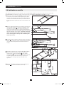
2 Align the pin holes in the ladder sections with the pin holes
in the assembly brackets and insert clevis pins B into the pin
holes (4 total). This step may be omitted to provide additional
installation flexibility, but installing the pins will make the
SRCABLELADDER accessory more stable. Warning: If you
choose not to install the clevis pins, make sure at least 25% of
the length of each assembly bracket is inside the ladder.
B
B
2
3 After inserting the clevis pins, insert a cotter pin C through the
hole at the end of each clevis pin. (The straight section of the
cotter pin goes through the hole.)
C
3
4 Using an assistant, lift the SRCABLELADDER accessory
(rungs upward) and insert the exposed hook ends of the
assembly brackets D into the corresponding slots E in the
SRCABLETRAY accessories installed at the top of each
enclosure. The hooks should fit the slots securely by sliding down
to engage the edge of the slot. Note: There are two levels of slots.
Use the slots that match your application best.
E
D
4
5
201105211 93-2973.indb 5
5/23/2011 12:56:46 PM