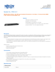
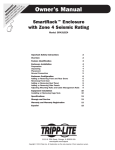
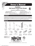
1
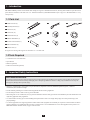
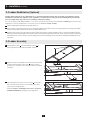
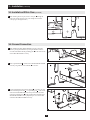
:
ty n or a Lite nty
a
f
y ipp arr
da Tr w
n
o
Owner’s Manual
/
arra ne t REE .com
i
W
nl F lite
r o in a ipp
egistratio
e
R ist o w .tr
g t
w
re ce ww
n
a t—
ch uc
od
pr
SmartRack™ Accessories
Model: SRCABLELADDER
1 – Introduction
2
1-1 Parts List
2
1-2 Tools Required
2 – Important Safety Instructions
2
2
3 – Installation
3
3-1 Planning
3
3-2 Ladder Modification (Optional)
4
3-3 Ladder Assembly
4
3-4 Installation Across Aisle
5
3-5 Installation Within Row
6
3-6 Ground Connection
7
4 – Storage and Service
8
5 – Warranty and Warranty Registration
8
1111 W. 35th Street, Chicago, IL 60609 USA
+1.773.869.1234 • www.tripplite.com
Copyright © 2008 Tripp Lite. All trademarks are the sole property of their respective owners.
1
1 – Introduction
SRCABLELADDER provides roof-mounted cable routing for Tripp Lite’s SmartRack Enclosures, allowing cable bundles to span aisles and/or
spaces between enclosures in the same row. Note: Standard installation of SRCABLELADDER requires Tripp Lite’s SRCABLETRAY accessory,
sold separately.
1-1 Parts List
A Ladder Sections (2)
A
D
G
B
E
H
C
F
I
B Assembly Brackets (6)
C Clevis Pins (12)
D Cotter Pins (12)
E Ground Brackets (2)
F M6 Hex-Head Bolts (2)
G 24-inch Ground Cables (3)
H M6 Lock Washers (4)
I M6 Hex Nuts (2)
If any parts are missing, call Tripp Lite for assistance at +1.773.869.1234.
1-2 Tools Required
• 13 mm Wrench or Crescent Wrench
• Tape Measure
• Hacksaw (optional)
• Drill with 3/8-inch Bit (optional)
2 – Important Safety Instructions
SAVE THESE INSTRUCTIONS
This manual contains instructions and warnings that must be followed during the installation and operation of the product described in this
manual. Read all instructions and warnings thoroughly before attempting installation. Failure to comply may invalidate the warranty and
cause property damage and/or personal injury.
• Install in a controlled indoor environment, away from moisture, temperature extremes, flammable liquids and gasses, conductive
contaminants, dust and direct sunlight.
• Provide suitable grounding in accordance with all applicable electrical wiring regulations.
• Do not attempt to climb or walk across any part of the ladder.
• When using tools to cut or drill metal, use eye protection and follow all other safety precautions recommended by the tool manufacturer and
required by applicable safety regulations.
• Use caution and wear safety gloves when handling metal parts that have been cut to length. Sharp edges can cause personal injury and
property damage.
• Use of this equipment in life support applications where failure of this equipment can reasonably be expected to cause the failure of the life
support equipment or to significantly affect its safety or effectiveness is not recommended. Do not use this equipment in the presence of a
flammable anesthetic mixture with air, oxygen or nitrous oxide.
2
3 – Installation
Note: Prior to installation, you must install the SRCABLETRAY accessory (sold separately) on each enclosure that will be linked by the
SRCABLELADDER accessory. For ordering information, call Tripp Lite Customer Service at +1.773.869.1234.
3-1 Planning
SRCABLELADDER can provide enclosure-to-enclosure cable routing across an aisle or within a single row. You can combine multiple
SRCABLELADDER and SRCABLETRAY accessories to meet the cable routing needs of almost any configuration of SmartRack Enclosures,
but planning and measurement are required to ensure a secure fit. Tripp Lite recommends that you read the entire manual in advance to gain a
clear understanding of the installation process and accessory positioning.
Sample Cable Routing Configuration (Top View)
SRCABLETRAY
SRCABLELADDER installed
between enclosures across an aisle.
SRCABLETRAY
SRCABLELADDER installed
between enclosures within a row.
SRCABLETRAY
Use a tape measure to determine the distance that SRCABLELADDER will bridge. (Preassembling the ladder sections will allow you to observe
their attachment points in place for a more accurate measurement.)
The standard length of SRCABLELADDER is 10 feet. If the standard length and the distance between attachment points differ, adjusting the
position of the SRCABLETRAY accessories will allow you to change the distance between attachment points. If necessary, you can use a single
ladder section instead of two sections, reducing the overall ladder length to approximately 5 feet. In addition, the assembly brackets at the ends
of the ladder sections will allow minor adjustments if you install them without pins, and you can add a few inches to the length of the ladder
by using the alternate pin holes for assembly. If the available adjustments will not accommodate the SRCABLELADDER accessory, you must
cut one of the ladder sections. See Section 3-2 Ladder Modification for instructions. If the SRCABLELADDER accessory will fit without
modification, proceed to Section 3-3 Ladder Assembly.
3
3 – Installation (continued)
3-2 Ladder Modification (Optional)
Warning: When using tools to cut or drill metal, use eye protection and follow all other safety precautions recommended by the tool
manufacturer and required by applicable safety regulations. Use caution and wear safety gloves when handling metal parts that have
been cut to length. Sharp edges can cause personal injury and property damage.
Note: Do not modify the SRCABLELADDER accessory unless you have followed the instructions in Section 3-1 Planning and determined that
modification is required. If modification is not required, proceed to Section 3-3 Ladder Assembly.
1 Measure and mark the cable ladder section that will be cut.
2 Use a hacksaw or other metal-cutting tool to cut through the ladder section. Make sure your cut is perpendicular to the length of the ladder
and use a metal-cutting tool that will not bend or crush the ladder section.
3 (Optional) After cutting, use a drill with a 3/8-inch bit to drill new pin holes in end of the ladder section. Compare the modified end of the
ladder section with the unmodified end to determine where holes should be drilled. Make sure that the hole location matches your planning
and measurements. You may omit this step, but drilling the pin holes and installing the pins will make the SRCABLELADDER accessory
more stable.
3-3 Ladder Assembly
1 Join the ladder sections A with two assembly brackets B by
inserting the brackets in the ends of the ladder sections.
A
B
1
2 Align the pin holes in the ladder sections with the pin holes in the
assembly brackets and insert clevis pins C into the pin holes
(4 total). Note: The ladder sections should be flush for a standard
installation.
C
C
2
3
After inserting the clevis pins, insert a cotter pin D through the
hole at the end of each clevis pin. (The straight section of the
cotter pin goes through the hole.)
D
Proceed to Section 3-4 Installation Across Aisle or Section 3-5
Installation Within Row, depending on your application.
3
4
3 – Installation (continued)
3-4 Installation Across Aisle
Note: Follow the instructions in this section only if the SRCABLELADDER accessory will be installed across an aisle. If the SRCABLELADDER
accessory will be installed within a row of enclosures, follow the instructions in Section 3-5 Installation Within Row instead.
1 Insert four assembly brackets A into the ends of the ladder. The
hooked ends of the brackets should be exposed. When the ladder is
oriented so that the ladder’s rungs are above the ladder’s side rails,
the hooked ends of the brackets should point down, as shown in
the drawing.
A
1
2 Align the pin holes in the ladder sections with the pin holes
in the assembly brackets and insert clevis pins B into the pin
holes (4 total). This step may be omitted to provide additional
installation flexibility, but installing the pins will make the
SRCABLELADDER accessory more stable. Warning: If you
choose not to install the clevis pins, make sure at least 25% of
the length of each assembly bracket is inside the ladder.
B
B
2
3 After inserting the clevis pins, insert a cotter pin C through the
hole at the end of each clevis pin. (The straight section of the
cotter pin goes through the hole.)
C
3
4 Using an assistant, lift the SRCABLELADDER accessory
(rungs upward) and insert the exposed hook ends of the
assembly brackets D into the corresponding slots E in the
SRCABLETRAY accessories installed at the top of each
enclosure. The hooks should fit the slots securely by sliding down
to engage the edge of the slot. Note: There are two levels of slots.
Use the slots that match your application best.
E
D
4
5
3 – Installation (continued)
3-5 Installation Within Row
Note: Follow the instructions in this section only if the SRCABLELADDER accessory will be installed within a row of enclosures. If the
SRCABLELADDER accessory will be installed across an aisle, follow the instructions in Section 3-4 Installation Across Aisle instead.
1 Insert four assembly brackets A in the open ends of the ladder,
hooked end first. When the ladder is oriented so that the ladder’s
rungs are above the ladder’s side rails, the hooked ends of the
brackets should point down, as shown in the drawing.
A
1
2 Align the pin holes in the ladder sections with the pin holes
in the assembly brackets and insert clevis pins B into the pin
holes (4 total). This step may be omitted to provide additional
installation flexibility, but installing the pins will make the
SRCABLELADDER accessory more stable. Warning: If you
choose not to install the clevis pins, make sure at least 25% of
the length of each assembly bracket is inside the ladder.
B
B
2
3 After inserting the clevis pins, insert a cotter pin C through the
hole at the end of each clevis pin. (The straight section of the
cotter pin goes through the hole.)
C
3
4 Using an assistant, lift the SRCABLELADDER accessory (rungs
upward) and align the holes at the ends of the assembly brackets
D with the corresponding holes E in the SRCABLETRAY
accessories installed at the top of each enclosure. Note: There are
two levels of holes. Use the holes that match your application best.
E
D
4
5 Align the pin holes and insert clevis pins
holes (4 total).
F
into each of the pin
F
5
6
3 – Installation (continued)
3-5 Installation Within Row (continued)
6 After inserting the clevis pins, insert a cotter pin G through the
hole at the end of each clevis pin. (The straight section of the
cotter pin goes through the hole.)
G
6
3-6 Ground Connection
1 After installing the SRCABLELADDER accessory, determine
where to place ground brackets by noting the distance between
one end of the ladder and the grounding post A at the corner of the
nearest SRCABLETRAY accessory.
A
1
2 Place a ground bracket B near the end of the SRCABLELADDER
accessory’s leg and use a hex-head bolt C to secure it.
B
C
2
3 Use the included hex nuts and lock washers G to connect one end
of the included ground cable H to a grounding post I at the corner
of the nearest SRCABLETRAY accessory and connect the other
end to the grounding post J of the ground bracket attached to the
SRCABLELADDER accessory. Repeat steps 1 to 3 for the other
end of the SRCABLELADDER accessory.
G
G
I
H
3
7
J
4 – Storage and Service
Storage
The unit must be stored in a clean, secure environment with a temperature less than 40° C (104° F) and a relative humidity less than 90%
(non-condensing). Store the unit in its original shipping container if possible.
Service
The unit is covered by the limited warranty described in this manual. For more information, call Tripp Lite Customer Service at
+1.773.869.1234.
5 – Warranty and Warranty Registration
Limited Warranty
Seller warrants this product, if used in accordance with all applicable instructions, to be free from original defects in material and workmanship
for a period of 5 years from the date of initial purchase. If the product should prove defective in material or workmanship within that period,
Seller will repair or replace the product, in its sole discretion.
THIS WARRANTY DOES NOT APPLY TO NORMAL WEAR OR TO DAMAGE RESULTING FROM ACCIDENT, MISUSE, ABUSE
OR NEGLECT. SELLER MAKES NO EXPRESS WARRANTIES OTHER THAN THE WARRANTY EXPRESSLY SET FORTH HEREIN.
EXCEPT TO THE EXTENT PROHIBITED BY APPLICABLE LAW, ALL IMPLIED WARRANTIES, INCLUDING ALL WARRANTIES OF
MERCHANTABILITY OR FITNESS, ARE LIMITED IN DURATION TO THE WARRANTY PERIOD SET FORTH ABOVE; AND THIS
WARRANTY EXPRESSLY EXCLUDES ALL INCIDENTAL AND CONSEQUENTIAL DAMAGES. (Some states do not allow limitations
on how long an implied warranty lasts, and some states do not allow the exclusion or limitation of incidental or consequential damages, so the
above limitations or exclusions may not apply to you. This Warranty gives you specific legal rights, and you may have other rights which vary
from jurisdiction to jurisdiction.)
Tripp Lite; 1111 W. 35th Street; Chicago IL 60609; USA
WARNING: The individual user should take care to determine prior to use whether this device is suitable, adequate or safe for the use intended.
Since individual applications are subject to great variation, the manufacturer makes no representation or warranty as to the suitability or fitness
of these devices for any specific application.
Warranty Registration
Visit www.tripplite.com/warranty today to register the warranty for your new Tripp Lite product. You’ll be automatically entered into a drawing
for a chance to win a FREE Tripp Lite product!*
* No purchase necessary. Void where prohibited. Some restrictions apply. See website for details.
Tripp Lite has a policy of continuous improvement. Specifications are subject to change without notice.
Made in China.
1111 W. 35th Street, Chicago, IL 60609 USA
+1.773.869.1234 • www.tripplite.com
8
200804136 93-2808