1
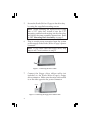
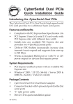
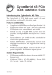
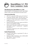
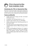
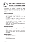
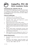
Hi-Speed USB 9-in-1
Reader/Writer + FDD
Quick Installation Guide
Introducing the Reader/Writer+Floppy
The Hi-Speed USB 9-in-1 Reader/Writer+Floppy easily adds
front-accessible multi-format memory card reader/
writer and floppy drive.
Features and Benefits
•
•
Fits into either 3.5" or 5.25" (with included mounting
rack) drive bay
Dual color Activity/Access LED:
- Red: Flash memory card interface
- Green: Floppy drive interface
Flash memory card interface
•
•
Compliant with USB specification rev. 2.0
Works with CompactFlash (CF) Type I & Type II,
Microdrive, SmartMedia (SM), SecureDigital (SD),
MultimediaCard (MMC) and Memory Stick
(incl. MagicGate & Pro) memory cards
Note: USB 2.0 devices are limited to USB 1.1
speeds when they are connected to a USB 1.1 host
adapter.
Floppy drive interface:
•
Supports 1.44MB floppy diskettes
04-0361C
1
System Requirements
•
•
•
•
Pentium or equivalent PC with an internal USB
port (USB 2.0 recommended) and internal floppy
drive controller
One available 3.5" or 5.25" drive bay
CD-ROM drive (for driver installation)
Windows 98SE/ME/2000 SP3 or later/XP/Server
2003/Vista
Package Contents
•
•
•
•
Hi-Speed USB 9-in-1 R/W+FDD
5.25" mounting rack and mounting kit
USB adapter (4-pin to type-A)
Quick Installation Guide
Layout
Depending on the model purchased, the color of your
product may vary from what is shown.
CF/Microdrive
Activity/Access
LED
Floppy disk
Figure 1. Front Panel
2
SM/SD/MMC/
Memory Stick
Floppy drive
connector
Floppy drive
power connector
Figure 2. Rear Panel
5.25" Mounting Rack Assembly
Important: Use the Mounting Rack Assembly only
when installing the hub into a 5.25" drive bay. Depending
on the model purchased, the color of your product may
vary from what is shown.
Figure 3. 5.25" Mounting Rack Assembly
3
4-Pin USB Connector
+5VDC (Pin 1)
Figure 4. 4-Pin USB Connector
Important: The 4-Pin USB Connector is designed to
plug into the 4 or 5-pin row of a USB pin-out header.
Make sure that +5VDC (Pin 1) is plugged into Pin 1 or
Pin 2 on the pin-out header.
Motherboard USB Pin-out Header
The typical internal USB Pin-out Header found on
motherboards consists of 9 pins arranged in 2 rows; each
header provides 2 USB ports. Match up +5VDC (Pin 1)
on the 4-Pin USB Connector to Pin 1 or Pin 2 on the
pin-out header. Connecting the USB cable improperly
may damage the system. Please refer to your system's
manual for proper connection.
Pin
Assignment
Pin
Assignment
1
+5VDC
2
+5VDC
3
USB- (Data-)
4
USB- (Data-)
5
USB+ (Data+)
6
USB+ (Data+)
7
Ground (GND)
8
Ground (GND)
9
None
10
Ground (GND)
Figure 5. USB Pin-out Header Table
Note: See Figure 4, above, for proper orientation
of the 4-pin USB Connector.
4
USB Adapter
This USB adapter is only needed if you plan to connect
the Reader/Writer+Floppy to a type-A USB port instead
of a USB pin-out header.
Match up +5VDC on the Reader/Writer+Floppy's 4-pin
USB Connector to +5VDC on the USB adapter.
Type-A connector
+5VDC
Figure 6. USB Adapter
Installing the Reader/Writer+Floppy
Important: In order for the Reader/Writer+Floppy to work
properly, the driver of your existing USB 2.0 host
adapter must be installed properly.
1.
2.
3.
4.
Turn OFF the power to your computer and all
connected peripheral devices.
Unplug the power cord from the back of the
computer.
Remove the computer’s cover.
Select an available 3.5" or 5.25" drive bay for the
Reader/Writer+Floppy, remove the cover plate from
the selected drive bay.
5
5.
Secure the Reader/Writer+Floppy to the drive bay
by using the supplied mounting screws.
Note: When installing the Reader/Writer+Floppy
into a 5.25" drive bay install it into the 5.25"
mounting rack before mounting into the drive bay
and follow the same assembly instructions. Refer
to 5.25" Mounting Rack Assembly on page 3.
6.
Plug in a mini power connector from the system
power supply to the Reader/Writer+Floppy's power
connector.
Note: If you don't need the floppy drive, skip
steps 6 and 7 and continue to step 8.
Figure 7. Connecting the Power Cable
7.
Connect the floppy drive ribbon cable (not
included) to the Reader/Writer+Floppy's floppy
drive connector. Make sure the stripe on the cable
is on the side opposite the power connector.
Stripe
Figure 8. Connecting the floppy drive ribbon cable
6
8.
Connect the Reader/Writer+Floppy's 4-pin USB
Connector to the system's internal USB port. Refer
to USB Pin-out Header, on page 4 for more
information. Check your system documentation
for the location of the USB pin-out header.
Note: If your system has an internal Type-A USB
port you may choose to connect the
Reader/Writer+Floppy's 4-pin USB connector via
the included 4-pin header to USB adapter. Refer
to Figure 6, on page 5 for more information.
9.
Replace the computer's cover and reconnect the
power cord.
Hardware installation is complete. Go to the next
section, Driver Installation to complete the installation.
Driver Installation
Windows 98SE
Please go to the SIIG Website, http://www.siig.com,
and download the latest driver and installation
instructions for Windows 98SE.
Windows ME/2000 SP3 or later/XP/Server 2003/Vista
Windows ME, 2000, XP, Server 2003 and Vista
automatically detects and installs the correct drivers for
this device. No driver installation is needed. Refer to
Accessing Memory Cards, on page 9, for the order in
which the memory slots appear.
7
To Verify Successful Driver Installation
1.
2.
3.
Check Device Manager to verify successful driver
installation.
Windows ME: Right click My Computer, click
Properties, then click Device Manager.
Windows 2000/XP/Server 2003: Right click My
Computer, click Manage, then click Device
Manager.
Windows Vista: Right click My Computer, click
Manage, click Continue, then click Device
Manager.
Double click Universal Serial Bus controllers. USB
Mass Storage Device should be listed.
Double click Disk drives. Generic 2.0 Reader...
should be listed two times.
Inserting Memory Cards and Floppy Disk
For CompactFlash, IBM MicroDrive, Memory Stick,
MultiMediaCard and SecureDigital memory cards,
insert with the top label facing up.
For SmartMedia memory card, insert with the top label
facing down and gold pins facing up.
For Floppy disks, insert with the top label facing up.
Note: The Activity/Access LED will be on (Red)
with no memory card inserted.
8
Accessing Memory Cards
When the Reader/Writer+Floppy is successfully installed,
two Removable Disk icons appear in My Computer.
To access any one drive, double click the icon that
corresponds to the memory card. The first removable
disk icon corresponds to CF and Microdrive memory
media. The second removable disk icon corresponds to
SmartMedia, SecureDigital, MultimediaCard and
Memory Stick memory media.
Activity/Access LED
The LED will be lit red when no flash memory card is
inserted. When any flash memory card is inserted, the
LED will go off.
Flash Memory Card
The LED will flash red when accessing any memory
card.
Floppy Drive
The LED will flash green when accessing a floppy
diskette.
Removing Inserted Media
Do not remove flash memory cards and/or a floppy
diskette when theActivity/Access LED is flashing/on.
Wait until the LED is off for several seconds before
removing any inserted media.
9
Blank Page
10
Technical Support and Warranty
QUESTIONS? SIIG’ s Online Support has answers! Simply visit
our web site at www.siig.com and click Support. Our online support
database is updated daily with new drivers and solutions. Answers
to your questions could be just a few clicks away. You can also
submit questions online and a technical support analysts will
promptly respond.
SIIG offers a 5-year manufacturer warranty with this product. Please
see our web site for more warranty details. If you encounter any
problems with this product,please follow the procedures below.
If it is within the store's return policy period, please return the
product to the store where you purchased it. If your purchase has
passed the store's return policy period, please follow these steps to
have the product repaired or replaced.
Step 1: Submit your RMA request.
Go to www.siig.com, click Support, then RMA to submit a
request to SIIG RMA. If the product is determined to be
defective, an RMA number will be issued. SIIG RMA department
can also be reached at (510) 413-5333.
Step 2: After obtaining an RMA number, ship the product.
• Properly pack the product for shipping. All accessories that
came with the original package must be included.
• Clearly write your RMA number on the top of the returned
package. SIIG will refuse to accept any shipping package, and
will not be responsible for a product returned without an RMA
number posted on the outside of the shipping carton.
• You are responsible for the cost of shipping the product to SIIG
at the following address:
SIIG, Inc.
6078 Stewart Avenue
Fremont, CA 94538, USA
RMA #: ________________
• SIIG will ship the repaired or replaced product via Ground
in the U.S. and International Economy outside of the U.S. at
no cost to the customer.
11
About SIIG, Inc.
Founded in 1985, SIIG, Inc. is a leading computer upgrade
manufacturer of I/O connectivity products, including PCI & ISA
serial and parallel ports, USB, Serial ATA & UltraATA controllers,
FireWire (1394a/b), networking, sound cards, and other accessories.
SIIG is the premier one-stop source of upgrades.
SIIG products offer comprehensive user manuals, many user-friendly
features, and are backed by an extensive manufacturer warranty.
High-quality control standards are evident by the overall ease of
installation and compatibility of our products, as well as one of the
lowest defective return rates in the industry. SIIG products can be
found in computer retail stores, mail order catalogs, through major
distributors, system integrators, and VARs in the Americas and the
UK, and through e-commerce sites.
PRODUCT NAME
Hi-Speed USB 9-in-1 R/W + FDD
FCC RULES: TESTED TO COMPLY WITH FCC PART 15, CLASS
B OPERATING ENVIRONMENT: FOR HOME OR OFFICE USE
FCC COMPLIANCE STATEMENT:
This device complies with part 15 of the FCC Rules. Operation is
subject to the following two conditions: (1) This device may not
cause harmful interference, and (2) this device must accept any
interference received, including interference that may cause
undesired operation.
THE PARTY RESPONSIBLE FOR PRODUCT COMPLIANCE
SIIG, Inc.
6078 Stewart Ave.
Fremont, CA 94538-3152, USA
Hi-Speed USB 9-in-1 R/W + FDD is a trademark of SIIG, Inc. SIIG and the SIIG logo are registered
trademarks of SIIG, Inc. Microsoft and Windows are registered trademarks of Microsoft Corporation.
Pentium is a registered trademark of Intel Corporation. Other names used in this publication are for
identification only and may be trademarks of their respective companies.
May, 2007
Copyright © 2007 by SIIG, Inc. All rights reserved.