1
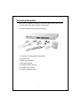
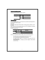
Longshine Technologie Europe GmbH
www.longshine.de
FCC Certifications
This Equipment has been tested and found to comply with the limits for a Class
A digital device, pursuant to part 15 of the FCC Rules. These limits are
designed to provide reasonable protection against harmful interference when the equipment is
operated in a commercial environment. This equipment generates, uses, and can radiate radio
frequency energy and, if not installed and used in accordance with the instruction manual, may
cause harmful interference to radio communications.
Operation of this equipment in a residential area is likely to cause harmful interference in which
case the user will be required to correct the interference at his own expense.
This device complies with Part 15 of the FCC Rules. Operation is subject to the following two
conditions: (1) this device may not cause harmful interference, and (2) this device must accept
any interference received; including interference that may cause undesired operation.
CE Mark Warning
This equipment complies with the requirements relating to electromagnetic
compatibility, EN 55022 class A for ITE, the essential protection requirement of Council
Directive 89/336/EEC on the approximation of the laws of the Member States relating to
electromagnetic compatibility.
Company has an on-going policy of upgrading its products and it may be possible that
information in this document is not up-to-date. Please check with your local distributors for the
latest information. No part of this document can be copied or reproduced in any form without
written consent from the company.
Trademarks:
All trade names and trademarks are the properties of their respective companies.
Copyright © 2004, All Rights Reserved.
Table of Content
Unpacking Information ..................................................................................1
1. Introduction to 24-port Fast Ethernet Web Smart Switch .......................2
1.1 General Description .............................................................................2
1.2 Key Features........................................................................................3
1.3 The Front Panel ...................................................................................3
1.4 The Rear Panel....................................................................................5
2. Installing 24 Fast Ethernet Web Smart Switch.........................................6
2.1 Desktop Installation..............................................................................6
2.2 Rack-mount Installation .......................................................................6
2.3 Installing Network Cables.....................................................................7
2.4 Network Application .............................................................................7
3. Management guide.....................................................................................8
3.1 Access the Switch................................................................................8
3.2 Home Page........................................................................................10
3.2.1 System ................................................................................... 11
3.2.2 Ports.......................................................................................12
3.2.3 VLANS ...................................................................................13
3.2.4 Aggregation/Trunking Configuration.......................................14
3.2.5 Qos.........................................................................................15
3.2.6 Discovery ...............................................................................16
3.2.7 Default....................................................................................17
3.2.8 Reboot....................................................................................17
4. Product Specifications.............................................................................18
Unpacking Information
Thank you for purchasing the 24-port Fast Ethernet Web Smart Switch. Before
you start, please check all the contents of this package.
The product package should include the following:
1. One 24-port Fast Ethernet Web Smart Switch
2. One power cord
3. Rubber foot and screws
4. Rack-mount brackets
5. One RS-232 Cable (Optional)
6. One CD for user’s manual
7. One Quick Installation Guide
1
1. Introduction to 24-port Fast Ethernet Web Smart
Switch
1.1 General Description
The device is a 24-port 10/100Mbps Ethernet Web Smart Switch.
Compare to the traditional 10/100Mbps Ethernet, the switch delivers a dedicated
Fast Ethernet connection to every attached client with no congestion issue. The
NWay auto-negotiation operation automatically negotiates with the connected
partners on the network speed and duplex mode; that provides an easy way to
integrate 10/100Mbps networks with no pain. It is ideal for micro-segmenting
large networks into smaller, connected subnets for improved performance,
enabling the bandwidth demanding multimedia and imaging applications.
Out of the ordinary dumb switches, the 24-port Fast Ethernet Web Smart Switch
embedded advanced management capability; that the device can be managed
through console port or web-based UI. This is much useful for system manager
to monitor and control the system efficiently.
Store-and-forward switching mode promises the low latency plus eliminates all
the network errors, including runt and CRC error packets. To work under
full-duplex mode, transmission and reception of the frames can occur
simultaneously without causing collisions as well as double the network
bandwidth.
The switch is plug-n-play without any software to configure and also fully
compliant with all kinds of network protocols. Moreover, the rich diagnostic LEDs
on the front-panel provide the operating status of individual port and whole
system.
2
1.2 Key Features
24 fixed 10/100Mbps Fast Ethernet ports for easy network connecting
application.
Provide Auto-discovery Function for easy Network management.
Provide 8K MAC address entries and 24 groups VLAN table
Support up to 4 ports and 6 groups port aggregation.
Supports 3 types of QoS priority for port base, 802.1p & TCP/IP
TOS/DiffServ(DS) priority field
Support full duplex flow control and half duplex back pressure
Store-and-forward forwarding scheme
Error packet filtering
Supports 320K bytes buffer Memory
Support local Console port or Web-based UI for configuration
Internal switching power supply (100-240Vac/50-60Hz)
1.3 The Front Panel
The front panel of the switch is shown as below
Port Operation
There are 24 * 100Mbps RJ-45 (copper) ports on the front panel.
The auto-negotiation feature of the switch allows each port of the device running
at one of the following operation modes:
Speed
Duplex Mode
Full Duplex
Half Duplex
Full Duplex
100Mbps
Half Duplex
10Mbps
All ports supports MDI/MDI-X auto crossover capability that is the port can
connect either the PC or hub without crossover cable adjustment.
3
Wiring for 10/100Mbps (Copper)
Following are the summaries of cabling required:
Media
10/100Mbps copper
Speed
Wiring
10Mbps Category 3,4,5 UTP/STP
100Mbps Category 5 UTP/STP
LEDs Definition
The rich diagnostic LEDs on the front panel can provide the operating status of
individual port and whole system.
Power LED
This indicator lights green when the switch is receiving power; otherwise, it is off.
Port LEDs
Every RJ-45 port on the front panel relevant one LED (10/100Mps) for indicating
the connection speed and activity status.
Port LED summary table
LED
10/100M
Status
Steady green
Statement
Connected as 10/100Mbps
Blinking green The port is transmitting/receiving data
If the port is connected but the Port LED is dark, check the following items:
The switch and the connected device’s power are on or not.
The connecting cable is good and with correct type
The cable is firmly seated in its connectors in the switch and in the
associated device
The connecting device, including any network adapter is well installed
and functioning
4
1.4 The Rear Panel
The rear panel of the switch is shown as below
5
2. Installing 24 Fast Ethernet Web Smart Switch
This switch can be placed directly on your desktop, or mounted in a rack. Users
can immediately use most of the features simply by attaching the cables and
turning the power on.
2.1 Desktop Installation
For desktop installation, the switch needs to put on a clean, flat desk or table
close to a power outlet. Plug in all network cables and the power cord, then the
system is ready.
Before installing the switch, you must ensure:
1. It is accessible and cables can be connected easily
2. Cabling is away from:
*Sources of electrical noise such as radios, transmitters and broadband
amplifiers
*Power lines and fluorescent lighting fixtures.
3. Keep water or moisture off
4. Airflow around the unit and through the vents in the side of the case is great
for heat radiation (company recommend that you provide a minimum of 25
mm clearance)
To prolong the operational life of your units:
1. Never stack unit more than eight sets high if freestanding
2. Do not place objects on top of any unit or stack
3. Do not obstruct any vents at the sides of the case
2.2 Rack-mount Installation
The switch may standalone, or may be mounted in a standard 19-inch equipment
rack. Rack mounting produces an orderly installation when you have a number of
related network devices. The switch is supplied with rack mounting brackets and
screws. These are used for rack mounting the unit.
Rack Mounting the Switch in the 19-inch rack:
1.
2.
3.
4.
Disconnect all cables from the switch before continuing.
Place the unit the right way up on a hard, flat surface with the front facing
toward you.
Locate a mounting bracket over the mounting holes on one side of the unit.
Insert the screws and fully tighten with a suitable screwdriver.
6
5.
6.
7.
Repeat the two previous steps for the other side of the unit.
Insert the unit into the 19" rack and secure with suitable screws (not
provided).
Reconnect all cables.
2.3 Installing Network Cables
Station Connections
Reference to the wiring statement of the previous section; connect each station to
the switch with correct type of cables.
Switch-to-Switch Connections
In making a switch-to-switch connection, use every port to connect another switch
or backbone is strongly recommended. The Fast Ethernet ports provide the fat pipe
to the server or backbone connectivity for boosting the total system performance.
Reference to the wiring statement of the previous section; connect each station to
the switch with correct type of cables.
2.4 Network Application
7
3. Management guide
This section instructs you how to enter and set up the configurations, which can be
accessed by RS-232 serial port (out-of-band) on the rear panel or by Telnet session /
Internet Browser over the network (in-band).
.
Factory Default value:
IP:
Subnet Mask:
Default Gateway:
192.168.1.1
255.255.255.0
192.168.1.254
3.1 Access the Switch
Console Port (Out-of-band) connection
The operating mode of the console port is:
DCE
9600 (Fix baud rate)
n (No parity checking)
8 (8 Data bits)
1 (1 stop bit)
None (No flow control)
After attaching a RS-232 cable (Straight-through) to the serial port of a PC
running a terminal emulation program, press “Enter” key then login screen
appears. Enter your username and password to login the management console.
Note:
:
The management functions of console program are exactly the same with
web-based management interface but in text mode.
Attention:
: 1. The factory default value of UserName and Password is
“admin”
2. System configurations via the Console Port only will be allowed
by the way of master device
8
In-Band Connections (Web Browser / Telnet)
To manage the switch through in-band access, you should configure the
management station with an IP address and subnet mask compatible with your
switch.
1. Running your Web Browser and enter the IP address “192.168.1.1” as the URL in
the “address” field.
2. Key in the User name and password to pass the authentication. The factory
default value of User Name and Password is “admin”.
3. After authentication procedure, the home page shows up.
9
3.2 Home Page
On the Home page, you can select the configuration by clicking the menu tabs
located on the upside of the UI.
It includes,
System
Ports
VLANS
QoS
Aggregation
Discovery
To restore the default Values of switch, Click the “Default” Button. If you want to
reboot the switch, click the “Reboot” Button.
10
3.2.1 System
To set up the system configurations such as login value, system name and IP
address.
Items
Mac Address
S/W Version
H/W Version
System name
IP Address
Subnet Mask
Gateway
Name
Password
Functions
The Mac Address of the switch
To check up the Software Version, see
this.
The Hardware version
Name of the Switch
Set up the IP of Switch
Set up the Subnet mask of Switch
Set up the Gateway of Switch
The Login name (default admin)
The Login password (default admin)
To save the configuration of the system, click “apply” to save
11
3.2.2 Ports
On the page, you can view the Port status, set up the Speed mode and enable
the FDX flow control.
Items
Functions
Admin Enable or Disable the Admin function
Bandwidth To control the bandwidth, you can select the
speed limitation you need in the drop list.
(Disable/128K/256K/512K/1M/2M/4M/8Mbps)
Operate mode Choose the Speed mode of port 10/100,
Half/Full. If you set to auto speed, it will be
auto-negotiation. (Auto Speed, 10M half, 10M
full, 100M half, 100M full)
Flow Control Enable or Disable the Flow control
Link/Status To show the status of each port. When it’s
green, it means the connection is down.
Otherwise, it’s red.
To save the configuration of the system, click “apply” to save. To see the latest
status of port, click refresh button.
12
3.2.3 VLANS
VLANS Configuration is for dividing the LAN into subnet groups for better
network management. (total 24 VLAN groups)
Mode:
1. Disable: Turn off the VLAN function by selecting the mode.
2. Port BASE: Group the port you select by entering the group number (Ex.1) in
VLAN textbox and selecting the port numbers (Ex.1, 2,3,4) you want.
Buttons
Add: Add the entry into the VLAN Table
Remove: Remove the Entry you select
Modify: Modify the Entry you select
Apply: Apply the Mode you select
Provides web manage security function, click enable VLAN group web manage
to support web manage function for VLAN group
13
3.2.4 Aggregation/Trunking Configuration
To set up the Port trunk groups, select “Enable” of the group you need. Don’t
forget to click the “Apply” to save the setting.
Supports 6 trunk groups for network application.
14
3.2.5 Qos
There are three modes of Quality of Service to choose, TOS, Tag Base, and Port
base. To Disable the QOS, click Disable and Click apply to save.
To use the TOS, select TOS and click Apply to save.
To enable the Tag Base, select Tag base and click Apply to save.
When you enable Port Base, packets from the port you select will have higher
priority.
To enable the Port base,
1. Select the port-base
2. Select the port-base ratio (1:4; 1:8; 1:16; Always High) The higher a ratio is,
the higher priority the port will get.
3. Select the ports in the table (High means high Priority, and Low means Low
priority). The priority depends on the Port Base rate.
4. Click apply to save
15
3.2.6 Discovery
When you install several 24port Fast Ethernet web-smart switches, the discovery
management tool helps you to search and access those switches on the LAN
easily. Therefore you can access any switch on your LAN without memorizing
those IP addresses. You can only find switches with the IP Address compatible
with the one you access.
Note. The Maximum number of Address list is 16.
Auto Search
1. Click the “Auto search” button to find the switches.
2. The IP address & name of Switch list will appear.
3. Click the one you want to access.
16
3.2.7 Default
To restore to default values,
1. Click the default button on the Howe page
2. Click “Yes” to enact. Don’t power off the switch while it’s work.
3.2.8 Reboot
To reboot the switch,
1. Click the Reboot button on the Howe page
2. Click “Yes” to enact. Don’t power off the switch while it’s work.
17
4. Product Specifications
Standard
Interface
Cable Connections
Network Data Rate
Transmission Mode
LED indications
Memory
Emission
Operating
Temperature
Operating Humidity
Power Supply
IEEE802.3 10BASE-T
IEEE802.3u 100BASE-TX
IEEE802.3x full-duplex operation and flow
control
IEEE802.1p Traffic prioritization
24 * 10/100Mbps auto MDI/MDI-X RJ-45
switching ports
1 * RS-232 Console port
RJ-45 (10BASE-T): Category 3,4,5 UTP/STP
RJ-45 (100BASE-TX): Category 5 UTP/STP
10/100Mbps Auto-negotiation
10/100Mbps Full-duplex, Half-duplex
System
Power
RJ-45 Port
10/100M Link/Act
8K MAC entries
320K bytes Buffer Memory
FCC Class A, CE
00 ~ 400C (320 ~ 1040F)
10% - 90%
Internal power 100-240V/ 50-60Hz
61LS-64240-207
18