1
INSTRUCTION MANUAL
LCD Monitor
Please read this Instruction book before using your LCD monitor.
We wish you many hours of pleasure from your new LCD monitor.
CE42LH2R
CE42LH2DPB
CE42LH2WP
TABLE OF CONTENTS
GB
TABLE OF CONTENTS . . . . . . . . . . . . . . . . . . . . . . . . 2
SAFETY PRECAUTIONS . . . . . . . . . . . . . . . . . . . . . . . 3
Installation and Use . . . . . . . . . . . . . . . . . . . . . . . . . . . . . . 3
SERVICING. . . . . . . . . . . . . . . . . . . . . . . . . . . . . . . . . . 4
Servicing . . . . . . . . . . . . . . . . . . . . . . . . . . . . . . . . . . . . . . 4
GB
Time menu. . . . . . . . . . . . . . . . . . . . . . . . . . . . . . . . . . . . . 9
Setup menu . . . . . . . . . . . . . . . . . . . . . . . . . . . . . . . . . . . . 9
PC Adj. menu. . . . . . . . . . . . . . . . . . . . . . . . . . . . . . . . . . .10
INSTALLATION MODE . . . . . . . . . . . . . . . . . . . . . . . .11
Installation Mode . . . . . . . . . . . . . . . . . . . . . . . . . . . . . . . .11
Federal Communications Commission Notice . . . . . . . . . 4
OPERATION . . . . . . . . . . . . . . . . . . . . . . . . . . . . . . . . 12
AC Power Cord Requirement . . . . . . . . . . . . . . . . . . . . . . 5
Selection of picture size . . . . . . . . . . . . . . . . . . . . . . . . . .12
End-User License . . . . . . . . . . . . . . . . . . . . . . . . . . . . . . . 5
PIP/POP Operation . . . . . . . . . . . . . . . . . . . . . . . . . . . . . .13
INSTALLATION . . . . . . . . . . . . . . . . . . . . . . . . . . . . . . 6
OPERATION (IN TEXT MODE) . . . . . . . . . . . . . . . . . 14
Step: 1 Mains Connection . . . . . . . . . . . . . . . . . . . . . . . . . 6
Teletext Operation . . . . . . . . . . . . . . . . . . . . . . . . . . . . . . .14
Step: 2 Connections . . . . . . . . . . . . . . . . . . . . . . . . . . . . . 6
Remote control . . . . . . . . . . . . . . . . . . . . . . . . . . . . . . . . . 7
Remote control battery installation . . . . . . . . . . . . . . . . . . 7
Controls and Menus . . . . . . . . . . . . . . . . . . . . . . . . . . . . . 8
Menu Operation. . . . . . . . . . . . . . . . . . . . . . . . . . . . . . . . . 8
Picture menu . . . . . . . . . . . . . . . . . . . . . . . . . . . . . . . . . . . 8
SPECIFICATIONS/HELPFUL HINTS . . . . . . . . . . . . . 15
6SHFL¿FDWLRQ . . . . . . . . . . . . . . . . . . . . . . . . . . . . . . . . . . .15
Helpful hints . . . . . . . . . . . . . . . . . . . . . . . . . . . . . . . . . . . .15
DIMENSIONS . . . . . . . . . . . . . . . . . . . . . . . . . . . . . . . 16
MENU OPERATION . . . . . . . . . . . . . . . . . . . . . . . . . . . 9
PC/DVI-D/COMPONENT SIGNAL SUPPORT
TIMING LIST . . . . . . . . . . . . . . . . . . . . . . . . . . . . . . . . .17
Picture menu . . . . . . . . . . . . . . . . . . . . . . . . . . . . . . . . . . . 9
RS232C COMMAND TABLES . . . . . . . . . . . . . . . . . . 18
Sound menu . . . . . . . . . . . . . . . . . . . . . . . . . . . . . . . . . . . 9
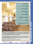
Robust monitor (CE42LH2R,CE42LH2DPB)
The robust monitor can be used in a wide variety of environments for dusty and oily circumstance such as fast food, digital signage, industrial
and public display.
LALUMINUM
CABINET & NON HOLES DESIGN
This monitor set uses Anodized aluminum and it has quite unique “Non-Holes” ventilation design which protects against mischief in the
public display applications and less maintenance when used in a dusty or oily environment.
Weather proof monitor (CE42LH2WP)
Weather resistant and water proof in accordance with the IP66 standard.
LANTI
REFLECTION TAMPER GLASS
This monitor set has a tough anti refection tampered glass. This offers the protection for the panel surface in the public display circumstance.
LALUMINUM
CABINET & NON HOLES DESIGN
This monitor set uses Anodized aluminum and it has quite unique “Non-Holes” ventilation design which protect against mischief in the
public display applications and less maintenance from dust and oil circumstance, and having perfect protection of IP66 weather-resistant
approval.
LEXTENSIVE
INPUT & OUTPUT TERMINALS (for all products)
This monitor set has various input and output terminals including component (Y,Pb,Pr) or RGBHV input and output with 5-BNC, composite video input and output with BNC, and RS-232 control port (serial D-Sub 9) input and output which offer the daisy chain connection.
7KHUHDUHFRPSXWHULQSXWVD'6XE5*%WHUPLQDODQG'9,'LQSXWZLWK+'&3IRU+LJKGH¿QLWLRQVLJQDOV7KHUHDUHDOVRMDFNVIRU
H[WHUQDOVSHDNHUV
Trademarks
(DFKQDPHRIFRUSRUDWLRQVRUSURGXFWVLQWKLVERRNLVHLWKHUDUHJLVWHUHGWUDGHPDUNRUDWUDGHPDUNRILWVUHVSHFWLYHFRUSRUDWLRQ
2
SAFETY PRECAUTIONS
GB
GB
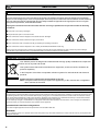
CAUTION: Please read and retain for your safety. This unit has been designed and manufactured to assure your personal safety, but
LPSURSHUXVHFDQUHVXOWLQSRWHQWLDOHOHFWULFVKRFNRU¿UHKD]DUGV,QRUGHUQRWWRGHIHDWWKHVDIHJXDUGVLQFRUSRUDWHGLQWKLVPRQLWRUREVHUYHWKH
following basic rules for its installation, use and servicing.
Installation and Use
Do not allow anything to rest on the power
cord. Do not locate this LCD monitor where the
FRUGZLOOEHGDPDJHGE\SHRSOHZDONLQJRQLW
Do not overload wall outlets and extension
FRUGVDVWKLVFDQUHVXOWLQ¿UHRUHOHFWULFVKRFN
$VXLWDEOHVRFNHWRXWOHWPXVWEHSURYLGHGQHDU
to the monitor and shall be easily accessible.
Do not place this LCD monitor near any heat
sources such as radiators, heaters, stoves and other heat-generating
SURGXFWVLQFOXGLQJDPSOL¿HUV
Do not place your LCD monitor on an unstable stand, shelf or table.
Serious injury to an individual, and damage to the LCD monitor may
result if it should fall. Your sales person can recommend an approved
ZDOOPRXQWLQJNLW$VSHFLDOZDOOPRXQWLQJNLWLVDYDLODEOHIRUWKLV
model.
This LCD monitor should be operated only from the type of power
source indicated on the monitor or as indicated in the Operating Instructions. If you are not sure of the type of power supply, consult your
sales person or your local power company.
For added protection it is strongly recommended that this LCD
monitor has its mains supplied via an approved earth fault protection
device.
WARNING: To prevent injury the LCD monitor must be securely
attached to the wall in accordance with the manufacturers installation
instructions.
Do not apply liquid cleaners or aerosol cleaners directly onto the LCD
monitor. Use a damp cloth for cleaning.
ADDITIONAL FOR NORTH AMERICA AND CANADA:
This monitor must NOT be permanently mounted to the building
structure. It must be mounted in such a way that it can be removed
using basic tools.
The power supply cord must NOT be attached to the building surface.
The power supply cord must NOT be routed through walls, ceiling,
ÀRRUVRURWKHUVLPLODURSHQLQJVLQWKHEXLOGLQJVWUXFWXUH
The power supply cord MUST be positioned so as to prevent physical
damage.
Important: (UK only)
THIS PRODUCT MUST BE EARTHED.
7KLVHTXLSPHQWLV¿WWHGZLWKDQDSSURYHGPDLQVOHDGDQGDQ
approved non rewireable UK mains plug. To change a fuse in this
type of plug proceed as follows:
1. Remove the fuse cover and fuse.
IMPORTANT:
This product must be earthed.
This unit is not disconnected from the mains unless the mains lead
LVXQSOXJJHG7KHLQVWDOOHUPXVWPDNHVXUHWKDWWKHZDWHUSURRILQOLQH
coupler is easily accessible.
(CE42LH2WP model only)
This monitor is tested to IP66 standard rating.
This monitor is not protected against temporary or continuous
immersion in liquid.
Do not use immediately after moving the LCD monitor from a low
temperature to a high temperature environment, as this causes conGHQVDWLRQZKLFKPD\UHVXOWLQ¿UHHOHFWULFVKRFNRURWKHUKD]DUGV
%HIRUHFOHDQLQJXQSOXJWKHPRQLWRUIURPWKHZDOOVRFNHW
Do notPRXQWQHDUDQRSHQÀDPHVRXUFH2SHQÀDPHVPXVWQHYHU
be used near this LCD monitor.
This LCD monitor should not be built in or enclosed in any way, heat
build up will reduce the life of the monitor.
This LCD monitor should have a minimum distance of 5cm away from
the wall and the monitor should have 10cm distance around the top
and sides.
AlwaysPRXQWXVLQJUHFRPPHQGHGDQGVXEVWDQWLDO¿[WXUHVDQG¿Wtings.
2. Fit a new fuse which should be a BS1362 13 Amp A.S.T.A. or
BSI approved type.
3.(QVXUHWKDWWKHIXVHFRYHULVFRUUHFWO\UH¿WWHG
If the fuse cover is lost or damaged the plug must NOT be used
but replaced with a serviceable plug.
,IWKH¿WWHGSOXJLVQRWVXLWDEOHIRU\RXUVRFNHWRXWOHWVLWVKRXOGEH
FXWRIIDQGDQDSSURSULDWHSOXJ¿WWHGLQLWVSODFH,IWKHPDLQVSOXJ
contains a fuse, this should have a rating of 13 Amp, ensure the
IXVHFRYHULVFRUUHFWO\¿WWHG,IDSOXJZLWKRXWDIXVHLVXVHGWKH
fuse at the distribution board should not be greater than 13 Amp.
Note: The severed plug must be destroyed to avoid a possible
VKRFNKD]DUGVKRXOGLWEHLQVHUWHGLQWRD$PSVRFNHWHOVHwhere.
The wires in this mains lead are coloured in accordance with the
following code:
Blue
Brown
Green and Yellow
Neutral
Live
Earth
1. The Blue wire must be connected to the terminal which is
PDUNHGZLWKWKHOHWWHU³1´RUFRORXUHG%/$&.
2. The Brown wire must be connected to the terminal with the
letter “L” or coloured RED.
3. The Green and Yellow wire must be connected to the terminal
ZKLFKLVPDUNHGZLWKWKHOHWWHU³(´RUFRORXUHG*5((1RU
GREEN and YELLOW.
10cm
5cm
10cm
(CE42LH2WP model only)
The operating temperature range of this monitor is guaranteed 0°C
~ 40°C/32°F ~ 104°F. It is not recommended to install the screen
in direct sunlight without adequate shading, as this will cause the
WHPSHUDWXUHRIWKHSDQHOWRULVHDERYHWKHPD[LPXPVSHFL¿HG'RLQJVRPD\FDXVHDEODFNVKDGRZWRDSSHDURQWKHVFUHHQZKLFK
will disappear when the screen temperature returns to within the
VSHFL¿FDWLRQ7KLV³RIFRXUVH´GRHVQRWSURGXFHDQ\KDUPIXOHIIHFW
on the lifetime of the monitor.
10cm
%HIRUHUHSODFLQJWKHSOXJFRYHUPDNHFHUWDLQWKDWWKHFRUGJULSLV
clamped over the sheath of the lead - not simply over the wires.
Do not attempt to bypass the safety purpose of the grounding
type plug.
7KHUHDU¿QQHGVHFWLRQDURXQGWKHFDELQHWIXQFWLRQVDVDKHDWVLQN
removing heat away from the monitor. The external surface of the
FDELQHW¿QQHGDUHDPXVWQRWEHFRYHUHGRUWKHDLUÀRZUHVWULFWHGLQ
anyway by enclosing the LCD monitor.
THIS UNIT IS NOT DISCONNECTED FROM THE MAINS UNLESS THE MAINS LEAD IS UNPLUGGED.
THE INSTALLER MUST MAKE SURE THE MAINS LEAD IS
EASILY ACCESSIBLE.
3
SERVICING
GB
GB
Servicing
Your monitor is fully transistorised and does not contain any user serviceable components.
You must not remove the rear cover of the monitor by yourself. The apparatus is working with high voltages and could damage
objects or even endanger people. Leave all required repair and service jobs to an authorised service technician. He will exclusively
use such spare parts that are complying with the same safety standards as applicable to the original parts. The use of original
VSDUHSDUWVFDQSUHYHQW¿UHVKRFNDQGRWKHUKD]DUGV
8QSOXJWKH/&'PRQLWRUIURPWKHZDOORXWOHWDQGUHIHUVHUYLFLQJWRTXDOL¿HGVHUYLFHSHUVRQQHOXQGHUWKHIROORZLQJ
conditions:
NIf the power cord or plug is damaged.
NIf liquid has been spilt in to the LCD monitor.
NIf the LCD monitor has been dropped or the cabinet has been damaged.
NIf the LCD monitor exhibits a distinct change in performance.
NIf the LCD monitor does not operate normally by following the operating instructions.
NIf the LCD monitor has been exposed to rain or water. (CE42LH2R/CE42LH2DPB model only)
Adjust only those controls that are covered in the operating instructions as improper adjustment of other controls may result in damage.
7KLVZLOORIWHQUHTXLUHH[WHQVLYHZRUNE\DTXDOL¿HGWHFKQLFLDQWRUHVWRUHWKHPRQLWRUWRQRUPDORSHUDWLRQ
Important recycling information.
Your SANYO product is designed and manufactured with high quality materials and components
which can be recycled and reused.
This symbol means that electrical and electronic equipment, at their end-of-life, should be disposed of separately.
In the European Union there are separate collection systems for used electrical and electronic
products.
Please help us to conserve the environment we live in!
Note:7KLVV\PEROPDUNDQGUHF\FOHV\VWHPDUHDSSOLHGRQO\WR(8FRXQWULHVDUHQRWDSSOLHGWR
other countries of the world.
Federal Communications Commission Notice
This equipment has been tested and found to comply with the limits for a Class A digital device, pursuant to Part 15 of FCC Rules. These limits
are designed to provide reasonable protection against harmful interference when the equipment is operated in a commercial environment. This
equipment generates, uses, and can radiate radio frequency energy and, if not installed and used in accordance with the instruction manual,
PD\FDXVHKDUPIXOLQWHUIHUHQFHWRUDGLRFRPPXQLFDWLRQV2SHUDWLRQRIWKLVHTXLSPHQWLQDUHVLGHQWLDODUHDLVOLNHO\WRFDXVHKDUPIXOLQWHUIHUence in which case the user will be required to correct the interference at his own expense.
'RQRWPDNHDQ\FKDQJHVRUPRGL¿FDWLRQVWRWKHHTXLSPHQWXQOHVVRWKHUZLVHVSHFL¿HGLQWKHLQVWUXFWLRQV,IVXFKFKDQJHVRUPRGL¿FDWLRQV
should be made, you could be required to stop operation of the equipment.
Canadian Radio Interference Regulations
This Class A digital apparatus meets all requirements of the Canadian ICES-003.
WARNING
7KLVLVD&ODVV$SURGXFW,QDGRPHVWLFHQYLURQPHQWWKLVSURGXFWPD\FDXVHUDGLRLQWHUIHUHQFHLQZKLFKFDVHWKHXVHUPD\EHUHTXLUHGWRWDNH
adequate measures.
4
GB
SERVICING GB
AC Power Cord Requirement
The AC Power Cord supplied with this LCD monitor meets the requirement for use in the country in which you
purchase it.
AC Power Cord for the United States and Canada:
$&3RZHU&RUGXVHGLQWKH8QLWHG6WDWHVDQG&DQDGDLVOLVWHGE\WKH8QGHUZULWHUV/DERUDWRULHV8/DQGFHUWL¿HG
by the Canadian Standard Association (CSA).
GROUND
$&3RZHU&RUGKDVDJURXQGLQJW\SH$&OLQHSOXJ7KLVLVDVDIHW\IHDWXUHWRPDNHVXUHWKDWWKHSOXJZLOO¿WLQWRWKHSRZHURXWOHW
Do not try to defeat this safety feature. Should you be unable to insert the plug into the outlet, contact your electrician.
THE SOCKET-OUTLET SHOULD BE INSTALLED NEAR THE EQUIPMENT AND EASILY ACCESSIBLE
End-User License
The product (meaning the equipment or appliance to which this documentation relates) incorporates Software (the software applications, utilities and modules embedded within the Product) which is owned by Sanyo or its licensors. Before using the product, please read the End-User
License Conditions detailed below. If you do not agree to the terms and conditions of the End-User License, Please do not proceed to use the
3URGXFWUHSDFNWKH3URGXFWXQXVHGDQGUHWXUQLWWR\RXUVXSSOLHUWRJHWKHUZLWKSURRIRISXUFKDVHIRUDIXOOUHIXQG%\XVLQJWKHSURGXFW\RX
agree to be bound by the terms and conditions of the End-User License.
/LFHQVH*UDQW&RQGLWLRQVDQGUHVWULFWLRQV
1. Sanyo grants you a non-exclusive, world-wide (subject to export controls), non-transferable (except as permitted by 2 below), royalty-free
license to use the Software upon and with the Product.
2. You may not transfer any of your license rights in the Software without the prior written consent of SANYO and if consent is provided then
the Software shall only be transferred in conjunction with the transfer of the Product AND provided that the transferee has read and agreed
to accept the terms and conditions of this license.
3.<RXPXVWHQVXUHWKDWWKHFRS\ULJKWWUDGHPDUNDQGRWKHUSURWHFWLYHQRWLFHVFRQWDLQHGLQWKH6RIWZDUHDUHPDLQWDLQHGDQGQRWDOWHUHGRU
removed.
4. The Software provided hereunder is copyrighted and licensed (not sold). SANYO especially does not transfer title or and ownership rights
in the Software to you. The Software provided hereunder may contain or be derived from portions of materials provided to SANYO under
license by a third party supplier.
5. Except as expressly permitted by statute you may not;
L
use the Software in conjunction with any other computer hardware other than the product;
L
copy all or part of the Software;
L
incorporate all (or any of) the Software into other programs developed by (or on behalf of) you and/or used by you;
L
reverse-engineer, decompile or disassemble the Software;
L
PDNHWKH6RIWZDUHRUDQ\SDUWRILWDYDLODEOHRUSHUPLWLWVUHGLVWULEXWLRQIRUXVHZLWKDQ\FRPSXWHUKDUGZDUHRWKHUWKDQWKH3URGXFWRU
rent, lease, gift, loan, sell, distribute or transfer possession of the whole or any part of the Software.
Termination
This license is effective until terminated. This license will terminate automatically without notice if you fail to comply with any of its provisions.
Disclaimer
1. The Software is(to the extent permitted by law) supplied “as is” and SANYO and its suppliers expressly exclude all warranties, express or
LPSOLHGLQFOXGLQJEXWQRWOLPLWHGWRZDUUDQWLHVRIVDWLVIDFWRU\TXDOLW\¿WQHVVIRUSXUSRVHDQGQRQLQIULQJHPHQWVDYHWRWKHH[WHQWWKDWWKH
same are not capable of exclusion at law).
2.,QQRFLUFXPVWDQFHVZLOO6$1<2EHOLDEOHIRUDQ\GLUHFWLQGLUHFWFRQVHTXHQWLDORULQFLGHQWDOGDPDJHLQFOXGLQJORVVRISUR¿WVEXVLQHVV
interruption, loss of data or the cost of procurement of substitute goods, technology or services) arising out of the use or the inability to use
the Software (save to the extent that such liability is not capable of exclusion at law).
General
1. This End-User License will be governed by laws of England and the User may only bring claims in the English Courts and SANYO shall be
entitled to bring a claim in the courts of any jurisdiction.
2. This End-User License is governed by the laws of the State of California. The End-User and Sanyo agree that any action to enforce or interpret the terms of this End-User License shall be brought only in the appropriate state or federal court located in Los Angeles County, California.The End-User and Sanyo hereby submit to the exclusive jurisdiction and venue of such court.
3. The above terms and conditions supersede any prior agreement, oral or written, between you and SANYO relating to the Software.
5
INSTALLATION
GB
GB
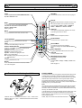
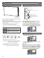
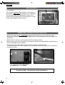
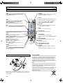
Step: 1 Mains Connection
N&RQQHFWWKHGLVSOD\XQLWWR9*$%1&DQG6FDUWFRQnector as required.
LD-Net
7KLV¿JXUHLV&(/+:3
1. Connect the in-line power connector to the Mains Inlet as shown
above.
2. Connect the power cord of the LCD monitor to a suitable wall outlet.
As this product does not have a mains On/Off switch, please
ensure your mains plug is easily accessible.
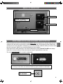
4. AV3
Composite (CVBS) signal input.
AV3-OUT can be used to output the incoming AV3 signal to the
other monitor.
5. DVI-D (Digital Video Interface)
DVI-D supports a large range of resolutions as shown on page 17.
The LCD monitor is prepared for a mains voltage AC100 ~ 240V,
50Hz/60Hz. To completely switch off the mains, or when the
display unit is not to be used for an extended period of time, it is
advisable to disconnect the power cord from the power outlet.
AC Main
s Outle
t
6. PC connection
PC input (PC-IN D-SUB). This input supports a large range of resolutions as shown page 17. Audio can be connected via the 3.5mm
PC-AUDIO IN.
7. External Speaker
Output the audio signal from AV1, AV2, AV3, PC and DVI.
7KHVSHDNHULPSHGDQFHLVRKPV
Please use the correct mains lead supplied with the set for your
area.
3. Warning: To prevent injury, the unit must be securely attached to
the wall in accordance with the installation instructions.
WARNING! High voltages are used in the
RSHUDWLRQRIWKLVVHW5HIHUVHUYLFHWRTXDOL¿HG
service personnel.
8. AV2 / DVI AUDIO IN
Connect the audio output (stereo) from a computer or video equipment connected AV2 or DVI.
Step: 2 Connections
NINPUT selection
7RVZLWFKHLWKHU$95*%$9$93&'9,RU1HWZRUNE\SUHVVing the INPUT button on your remote control repeatedly.
1. AV1
SCART connection/CVBS/RGB/S-VIDEO.
2. RGB
TTL input (5V RGB signals) into SCART terminal.
<3E3U5*%+9FRQQHFWLRQ$9
Choose Y, Pb, Pr or RGB H/V connection by selecting AV2 Setting
in Set up menu (see page 10). You can connect your DVD player
to the Y, Pb, Pr terminals instead of using a scart lead. This can
VXSSRUWKLJKGH¿QLWLRQLQDQDORJXHFRPSRQHQWIRUP5*%+9FDQ
be used as a PC input via the BNC terminals. Both options support
a large range of resolutions (page 17). AV2-OUT can be used to
output the incoming AV2 signal to the other monitor.
6
9. Monitor Audio OUT
7KLVWHUPLQDOVRXWSXW¿[HGOHYHOIURP$8',2,1
10. RS232C IN/OUT
:KHQWKHPRQLWRULVFRQWUROOHGE\DFRPSXWHUFRQQHFWWRWKLVMDFN
with serial control cable.
You can connect to another monitor with RS232C OUT.
:KHQ\RXFRQQHFW3&ZLWK56&VHOHFW³21´DW1HWZRUN
standby in Installation mode.
If it is selected “OFF”, RS232C terminals do not functional. Also
select push button to “SERIAL PORT”.
GB
INSTALLATION GB
Remote control
Input
Standby
To switch input source from AV1, RGB, AV2, AV3,
PC, DVI or Network mode.
To switch the monitor on and off. Also see page 8.
Recall
Wide
To select the screen mode Full, Full All, Zoom
16:9, Title in 16:9, Zoom 14:9, Title in 14:9,
Normal or Natural wide.
Refer to page 12.
Menu
To enter and exit the main menu, and sub menu.
To display input selection information and the Time
set.
You can also select colour systems in AV1/AV3
mode as follows: AUTO í PAL í SECAM í
NTSC í NTSC4.43 í PAL M í PAL N.
Auto PC
It can also be automatically adjusted in PC mode
by pressing this button for twice .
Back
Used to return to the previous menu.
Level Up/Down
To adjust the sound volume level or enter sub
menus.
F/OK
7RFRQ¿UPWKHLQLWLDOVHWWLQJLQWKHPHQX
Picture mode selector
Press the button repeatedly to select the following picture mode.
Personal - Personal preference mode.
Standard - Normal viewing mode.
Dynamic - Suitable for brightly lit rooms.
Soft - Low contrast setting
Eco - Suitable for dimly lit rooms and gives a cinHPDOLNHHIIHFW
)UHH]H
To switch picture still on or off.
Green
Press this button for more than 5 seconds, installation mode will appear.
Remote control battery installation
Up and Down
To select the next or previous item.
Sound Mute
7RPXWHWKHVRXQGIURPWKHVSHDNHUV
The sound changes as follows: Normal volume
Mute.
Bass Expander
To get an emphasised bass sound ON or OFF.
TXT/TV
To select Teletext mode.
Main/Sub Picture Swap
To swap Main and Sub picture.
ON/OFF
To switch OFF í PIP(1) í PIP(2) í POP mode
in turn.
Refer to page 13.
FOR EU USERS
7KHV\PEROPDUNDQGUHF\FOLQJV\VWHPVGHVFULEHGEHORZDSSO\WR(8
countries and do not apply to countries in other areas of the world.
Your SANYO product is designed and manufactured with high quality
materials and components which can be recycled and/or reused.
7KHV\PEROPDUNPHDQVWKDWHOHFWULFDODQGHOHFWURQLFHTXLSPHQW
batteries and accumulators, at their end-of-life, should be disposed of
separately from your household waste.
Note:
,IDFKHPLFDOV\PEROLVSULQWHGEHQHDWKWKHV\PEROPDUNWKLVFKHPLcal symbol means that the battery or accumulator contains a heavy
metal at a certain concentration. This will be indicated as follows: Hg:
mercury, Cd: cadmium, Pb: lead
In the European Union there are separate collection systems for used
electrical and electronic equipment, batteries and accumulators.
Please, dispose of them correctly at your local community waste collection/recycling centre.
,QVWDOOWZR³$$´YROWEDWWHULHVVRWKDWWKH³´DQG³±´PDUNVRQWKH
EDWWHULHVPDWFKWKH³´DQG³±´PDUNVLQVLGHWKHXQLWLQWRWKHUHPRWH
control handset.
Please, help us to conserve the environment we live in!
7
GB INSTALLATION
GB
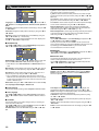
Controls and Menus
Menu Operation
Many of your monitors functions are controlled through the menu
function, using the remote control.
MENU
Picture
Sound
q
Time
Current Weekday
Current Time
1 - 20
Schedule
Weekday
Time
Action
Power On / Power Off
On Program
AV1 / RGB / AV2 / AV3 / PC / DVI / Network
On / Off
Active
Setup
Menu Setup
Language / H/V-Position / Duration / Transparence
PIP / POP Setup
PIP/POP Mode / Main/Sub Source / PIP Position
Initial Settings
Western / Eastern / Russian / Arabic / Farsi
Text Language
Tile Mode Active / H/V_Sets / H/V Location / Bezel H/V Adjustment
Tile Mode
AV2 Setting
RGBHV / YPbPr
XGA / WXGA 1366x768
XGA Mode
PC Power save
On / Off
w
å The LCD display has a Standby light to show there is power.
Switching into/from standby mode
The Standby mode is used for switching the LCD monitor off for short
periods of time. In standby mode the monitor is switched off but is still
receiving mains power.
L
To turn the monitor into standby mode, press the button.
The blue power indicator illuminates more brightly.
L
To turn the monitor ON from standby mode, press the button
again.
Brightness
Contrast
Color
Tint (only if NTSC equipment is detected)
Sharpness
White Tone
White Tone / R / G / B
Advanced Setting
DCDi / ACC/ACM / CCS / DNR / MPEG NR / Film Mode
Treble
Bass
Balance
On / Off
Bass Expander
PC Adj.
Auto Adjust
H-Position
V-Position
Clock
Phase
During menu operation the bottom of the on screen display will show
which controls can be used for menu navigation.
Press the MENU button to enter the main menu. Whenever main
menu is accessed initially, PICTURE will be the default selection.
A sub menu is selected using the or button and pressing
the or button when the required sub menu is highlighted.
:KHQ\RXKDYH¿QLVKHG\RXFDQSUHVVWKHBACK button to return to
the previous menu, press the MENU button to exit the menu operation.
,I\RX¿QGWKHSRZHULQGLFDWRUÀDVKLQJGLVFRQQHFW
power cord from the power outlet and contact our
6HUYLFHGHVN
7KLVZDUQLQJLVDVLJQWROHW\RXNQRZWKDWWKH
power protection function of this TV set is now
operating.
Picture menu
ç
Control buttons (bottom corner of back cover)
1. Press the MENU button. PICTURE will be the default selection.
Press the or button to enter.
Set the picture settings for your “personal” preference.
Menu button: Used to display or cancel main menu.
Input/4 button: Switch between AV1, RGB, AV2, AV3, PC , DVI
RU1HWZRUNPRGH,WLVDOVRXVHGWRSURYLGHVXE
menu selection from the Main Menu.
or buttons: provide up and down adjustments.
button: To switch to standby mode (to switch off completely
disconnect the monitor from the power supply).
8
2. Use the or button to select eg. Brightness and the or
button to adjust levels.
N White Tone
May be used to adjust the color tone of the picture. Use the or
button to select White Tone and press the or button
to enter the sub menu. You can select Personal, Cool, Standard or
Warm settings by using the or button. To adjust the color
tone of the picture by using the or button to select Red(R),
Green(G) or Blue(B) and the or button to adjust levels.
These settings will be stored in personal mode automatically.
MENU OPERATION
GB
Picture menu
GB
N Current Weekday
8VHWRVHWFXUUHQWZHHNGD\XVLQJWKH or button.
NAdvanced settings
Use the or button to select Advanced settings and press
the or button to enter the sub menu as follows.
N Current Time
Use to set the current time using the Numeric buttons.
Other items in Time Menu should not be selected until Current
Time has been set.
N Schedule
Use to set up to 20 separate time schedules for “Power On” or “Power
Off”, select 1 ~ 20 using the or button.
DCDi (Directional Correlational Deinterlacing) is used to process
moving angled edge in deinterlacing to get the smoothest and most
natural image. Press the or button on the remote control to
select On or Off.
N Weekday
8VHWRVHWWKHVFKHGXOHIRU³3RZHU2Q´RU³3RZHU2II´RIDQ\ZHHNGD\
from Sunday through to Saturday or Everyday using the or button.
ACC/ACM (ACC: Adaptive Contrast and Color; ACM-II: Active Color
Management-II) is used to select adaptive Brightness, Contrast and
tone control. Press the or button on the remote control to
select suitable mode either Vivid, Cinema, Sport or Off.
N Time
CCS (Cross Color Separation) is used to remove residual chroma
information from luminance signal which is the result of imperfect
decoding of composite video. Press the or button on the
remote control to select either Auto, Standard or Off.
N Action
DNR (Digital Noise Reduction) is available for noise reduction. Press
the or button on the remote control to select either Auto,
Low, Mid, High or Off.
MPEG NR (MPEG Noise Reduction): Removes unwanted ringing and
EORFNQRLVHIURPLPDJHVWKDWKDYHXQGHUJRQH03(*RU-3(*FRPpression and decompression. Press the or button on the
remote control to select On or Off.
Film Mode,QYHUVHSXOOGRZQ)LOPYV9LGHR'HWHFW¿OP3HUIRUPHG
on material which underwent technologic conversion to video. Press the
or button on the remote control to select On or Off.
Sound menu
Press the MENU button and select Sound using the or buttons, press the or button to enter.
Use to set the schedule for “Power On” or “Power Off” of any time using the Numeric buttons.
Use to set the schedule for “Power On” or “Power Off” active using
the or button.
You can set Power On timer in Time menu selecting “ON” in “On
Timer Function” in Installation Mode. If it is selected “OFF”, Power On
display in Time menu does not functional.
N On Program
Use to select AV1, RGB, AV2, AV3, PC, DVI or Network for the
schedule of “Power On” using the or button.
N Active
Use to select ON or OFF using the or button. When set
³2))´WKHDERYHLWHPV³6FKHGXOH´³:HHNGD\´³7LPH´³$FWLRQ´RU³21
Program” will be inactive.
Use NUMERIC buttons [0 ~ 9] to set On Time. (Action “Power On”
– 00:00 ~ 23:59)
Once On Time has been set, when the set time is reached, the
monitor will leave the stand-by status and enter to the source
automatically.
After On Time has been set, you can go on watching other programs. When the set time is reached, the monitor will automatically
switch to the preset program.
On Program can only be selected whenAction (Power On) has
been set.
Select and adjust to obtain the best sound settings for your environment using the or button to select Treble, Bass or Balance
and the or button to adjust levels.
Bass Expander can also be selected using the or button
and pressing the or button to select On or Off.
These settings automatically store when you exit the menu.
Press the BACK button to return to the previous menu.
Press the MENU button to exit menu operation.
Time menu
Action (Power Off) can be set to turn the monitor into standby at a
selected time
Once On Program has been set, when the set time is reached, the
monitor will enter to the preset source automatically.
Use the or button to select On program, AV1, RGB, AV2,
AV3, PC, DVI or Network.
Setup menu
Press the MENU button and select Setup using the or buttons, press the or button to enter. Press the BACK button to return to the previous menu. Press the MENU button to exit.
Press the MENU button and select Time using the or buttons, press the or button to enter. Press the BACK button to return to the previous menu. Press the MENU button to exit
menu operation.
N Menu Setup
Whenever Setup menu is accessed initially, Menu Setup will be the
default selection. Press the or button to enter the sub menu.
9
GB MENU OPERATION
GB
H_Sets is used to divide the horizonal picture into more than one
part, but the most is 5 parts (5 monitors).
V_Sets is used to divide the vertical picture into more than one part,
and the most is also 5 parts (5 monitors). Using the or button to set.
H Location is used to select one part of the horizonal picture to display on the current LCD Monitor using the or button.
Language is used to select the preferred language. Use the or
button to select English, French, German, Italian, Spanish or
Dutch.
H-Position changes the OSD position horizontally by using the or button.
V-Position changes the OSD position vertically by using the or
button.
Duration is used to set the display time of the MENU by using the
or button. (5 ~ 120 seconds)
Transparence is used to adjust transparence of menu display. Use
the or button to adjust levels.
N PIP/POP Setup
Use the or button to select PIP/POP Setup and press the
or button to enter the sub menu.
V Location is used to select one part of the vertical picture to display
on the current LCD Monitor using the or button.
%H]HO+$GMXVWPHQW is used to align the image horizontally with
respect to the other monitors in the video wall to accommodate the
bezel width using the or button. (0 ~ 10)
%H]HO9$GMXVWPHQW is used to align the image vertically with respect
to the other monitors in the video wall to accommodate the bezel
width using the or button. (0 ~ 10)
N AV2 Setting
Use the or button to select AV2 Setting and press the or button to select YPbPr or RGBHV.
Connect your PC to either PC-IN or RGBHV on the rear of the set.
Once connected select PC mode or AV2 (RGBHV, see page 6 for AV2
input settings) via the INPUT button on your remote control.
The set will become a monitor for the PC.
N XGA Mode
Use the or button to select XGA Mode and press the or
button to select XGA or WXGA 1366 x 768.
N PC Power Save
PIP/POP Mode: Using the or button select the most suitable mode PIP1, PIP2, POP or Off. (Please refer to page 13.)
When Mode is set to Off, Sub Source and PIP Position will not
ZRUN
Main Source is used to select input source (AV1, RGB, AV2, AV3, PC,
'9,RU1HWZRUNIRUPDLQSLFWXUHE\XVLQJWKH or button.
Sub Source is used to select input source (AV1, AV2, AV3, PC or
DVI) for sub picture by using the or button.
The monitor set automatically turns off with no PC input signal and
ZDNHVXSZLWKVLJQDOZKLOH3&3RZHU6DYHLVDFWLYH
Use the or button to select PC Power Save and press the
or button to select ON or OFF.
PC Adj. menu
Press the MENU button and select PC Adj. using the or buttons, press the or button to enter. Press the BACK
button to return to the previous menu. Press the MENU button to
exit menu operation.
For a combination of main picture and sub picture: only DVI or
1HWZRUNLQSXWFDQDVVHPEOHZLWKRWKHULQSXWVRXUFH)RUH[DPSOH
if main source is selected as AV1 input, then the sub source must
EH'9,RU1HWZRUNLQSXW
PIP Position: Using the or button it can be selected Top
Left, Top Right, Bottom Right or Bottom Left.
N Initial Settings
This function returns all setting values except for Installation Mode.
N Text Language
Use the or button to select Text Language and press the
or button to select Western, Eastern, Russian, Arabic or
Farsi.
N Tile Mode
This function allows you to split an image to suit your monitor grid
format to create a video wall.
Use the or button to select Tile Mode and press the or
button to enter the sub menu as follows.
Tile Mode Active can be set On or Off using the or button.
10
Auto Adjust is used to automatically detect incoming signal, and
adjust itself to optimize its performance by using the or button. If the image is not displayed properly, a manual adjustment is
required (Refer to following adjustments).
H-Position is used to move the horizontal picture position by using
the or button.
V-Position is used to move the vertical picture position by using the
or button.
ClockLVXVHGWRHOLPLQDWHÀLFNHUIURPWKHLPDJHE\XVLQJWKH or
button.
Phase is used to eliminate disorder from the image by using the or button.
INSTALLATION MODE
GB
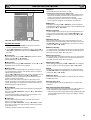
Installation Mode
Installation Mode
On program
Tuner Menu
Max Volume
Winter mode
RC inhibition
Child Lock
Address
Baud rate
Panel protection
AV Auto shut off
Network Standby
On Timer Function
LED light setting
DCR
Network initial
Temperature Error
IP Address
Subnet
Gateway
DNS
Select
Adjust
G2.02 0000
Off
Off
63
Off
Off
Off
0
19200
Off
Off
On
Off
Off
Off
>>>
0
000000000000
000000000000
000000000000
000000000000
MENU
GB
N Address
Set the address for the LCD monitor (0 ~ 999).
LSetting
the monitor address in RS232 mode
(DFKPRQLWRUFDQKDYHDVSHFL¿F$GGUHVVZKLFKKHOSVFRPPDQG
that monitor individually and will not effect to other monitors connected to a controlling PC Address format command.
The addressing format command is used for operating multiple
monitor sets from a single PC via the RS232C command line.
N Baud rate
Select Baud rate using the or button. To set transmission
speed RS232 or LD-NET communication for 19200 or 9600 Baud rate
by pressing the or button.
N Panel protection
7RSUHYHQWLPDJHVWLFNLQJZKLFKPD\RFFXUVKRZLQJVWLOOSLFWXUHIRUD
long time, select “Panel Protect” using the or button, once
highlighted you can select ON or OFF by pressing the or button.
Exit
N AV Auto shut off
This LCD monitor allows you to set up the following:
SETTING PROCEDURE
1. Press and hold the GREEN button on the remote control for 5
seconds. (Installation Mode will appear)
With no picture input signal to AV1, RGB, AV2(YPbPr), AV3, DVI,
1HWZRUNVHWWXUQVRIIDXWRPDWLFDOO\6HOHFW³$9$XWR6KXW2II´XVLQJ
the or button, once highlighted you can select On or Off by
pressing the or button.
N Network Standby
2. Use the or button to highlight each option, use the or
button to adjust each option. Press the MENU button to exit
the mode.
<RXFDQVDYHSRZHUFRQVXPSWLRQVHOHFWLQJ³2II´DW1HWZRUN6WDQGE\
in Installation mode, both RS232C and LD-NET do not functional. To
PDNHWKHPIXQFWLRQDOVHOHFW³21´LQWKLVPHQX
N On Program
N On Timer Function
Select ON program using the or button, select the start up
position using the or buttons.
2II$95*%$9$93&'9,RU1HWZRUN
You can save power consumption selecting “Off” at On Timer function
in Installation mode. On Timer in Time menu does not functional. To
PDNHWKHPIXQFWLRQDOVHOHFW³21´LQWKLVPHQX
N Max Volume
N LED Light setting
Select Max volume using the or button, use the or buttons to set the maximum volume required.
Select LED Light setting using the or button, once highlighted you can select On or Off by pressing the or button.
N Winter mode
N DCR
This Function can be activated when the LCD monitor is used durLQJFROGWHPSHUDWXUHFRQGLWLRQVDSSUR[LPDWHO\Û)Û&RUEHORZWR
maintain picture performance.
Using the or button select winter mode, once highlighted you
can select ON or OFF by pressing the or button.
IMPORTANT: The AC cord should not be disconnected during the
operation of Winter mode function.
When in winter mode, power consumption is higher than normal
standby consumption. This is entirely due to the operation of heating
circuitry. We strongly recommend to turn off Winter mode when the
DPELHQWWHPSHUDWXUHLVDERYHÛ)Û&
The picture contrast improved while DCR is ON. Select DCR using
the or button, once highlighted you can select On or Off by
pressing the or button.
The recorded number of abnormal temperature is occurred is indicated here.
N RC inhibition
N IP Address/Subnet/Gateway/DNS
You can prevent unwanted remote control operation by selecting RC
Inhibition.
Select using the or button. Press the or button to
select On or Off.
To re-instate RC operation press and hold the green button on the
remote control and select RC inhibition OFF.
These 4 items display the LD-Net information. If LD-NET is NOT connected, all the items would be displayed as “000000000000”.
N Network Initial
This function automatically installs the IP Address, Subnet, Gateway
and DNS information.
N Temperature Error
Disconnecting the mains supply before exiting Installation Mode will
cancel the following features On program, RC inhibition, Address
and Baud Rate.
N Child Lock
You can prevent unwanted operation of the LCD monitor via the
buttons on the rear of the monitor.
Select using the or button. Press the button to select
2QRU2))7KH³&KLOG/RFN´26'ZLOODSSHDULIEXWWRQVDUHSUHVVHG
ZKHQFKLOGORFNLV2Q
6
WDQGE\RSHUDWHVQRUPDOO\ZKHQFKLOGORFNLVVHW³2Q´
11
GB
GB
OPERATION
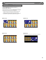
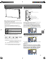
6HOHFWLRQRISLFWXUHVL]H
Select screen size from FULL, FULL ALL, ZOOM 16:9, TITLE IN 16:9,
ZOOM 14:9, TITLE IN 14:9, NORMAL or NATURAL WIDE by pressing
the WIDE button repeatedly on the Remote Control.
When in AV2 (RGBHV) or PC mode FULL or NORMAL can be
selected.
Note: Full - Set display area 100%
Only in DVI or AV2 (YPbPr) displaying high resolution content
FULL and FULL ALL are selectable.
Note: FULL - Set display area 95%
FULL ALL - Set display area 100%
All other inputs AV1, AV3, DVI or AV2 (YPbPr) (displaying lower resolutions) can select all picture sizes.
N Full/Full All
4:3
N Title In 14:9
14:9
The whole screen The whole screen
LV¿OOHGVWUHWFKLQJ LV¿OOHGVWUHWFKLQJ
the height slightly
the width.
at the edges.
16:9
The whole screen
LV¿OOHGZLWKWKH
corrrect picture
ratio.
Letterbox Video
7KHEODFNEDUV
top and bottom
are present and
the height is
compressed.
4:3
14:9
16:9
TITLES ON SCREEN
TITLES ON SCREEN
TITLES ON SCREEN
As zoom (14:9),
but bottom is
compressed even
more to allow
subtitles to be
seen.
As zoom (14:9),
but bottom is
compressed even
more to allow
subtitles to be
seen.
As zoom (14:9),
but bottom is
compressed even
more to allow
subtitles to be
seen.
As zoom (14:9),
but bottom is
compressed even
more to allow
subtitles to be
seen.
14:9
16:9
Letterbox Video
TITLES ON SCREEN
N Normal
N Zoom 16:9
4:3
14:9
16:9
Letterbox Video
4:3
The correct
picture width is
maintained but
the top and bottom are cropped.
Zooms in slightly
cropping the top
and bottom.
Zooms in slightly
cropping the top
and bottom.
7KHEODFNEDUV
top and bottom
are smaller and
the picture height
is compressed
slightly.
The correct ratio
is maintained with
EODFNEDUVRQWKH
left and right.
4:3
14:9
16:9
Letterbox Video
TITLES ON SCREEN
TITLES ON SCREEN
TITLES ON SCREEN
As Zoom (16:9),
but bottom is
compressed even
more to allow
subtitles to be
seen.
As Zoom (16:9),
but bottom is
compressed even
more to allow
subtitles to be
seen.
As Zoom (16:9),
but bottom is
compressed even
more to allow
subtitles to be
seen.
As Zoom (16:9),
but bottom is
compressed even
more to allow
subtitles to be
seen.
4:3
14:9
16:9
Letterbox Video
The correct
picture width is
maintained but
the top and bottom are cropped.
Zooms in slightly
cropping the top
and bottom.
Zooms in slightly
cropping the top
and bottom.
7KHEODFNEDUV
top and bottom
are smaller and
the picture height
is compressed
slightly.
N Title in 16:9
%ODFNEDUV
left and right,
picture height is
stretched.
%ODFNEDUV
left and right,
picture height is
stretched.
%ODFNEDUVOHIW
right, top and
bottom.
N Natural Wide
4:3
14:9
16:9
Letterbox Video
TITLES ON SCREEN
N Zoom 14:9
12
Letterbox Video
Stretches the pic- The height is exture horizontally
SDQGHGWR¿OOWKH
WR¿OOWKHVFUHHQ whole screen.
The picture is
more stretched at
the edges.
7KHSLFWXUH¿OOV
the screen and
is proportionally
correct.
7KHEODFNEDUV
top and bottom
remain and the
height is comSUHVVHGWR¿WWKH
picture area.
GB
OPERATION GB
PIP/POP Operation
Using this function, you can enjoy a DVI or Network program and an
image (AV1, AV2, AV3 or PC input) at the same time.
Press the ON/OFF button on the Remote Control repeatly to select
PIP1, PIP2, POP or OFF mode.
During the PIP/POP mode, press the Main/Sub Picture Swap button will switch the location for main and sub picture.
Only the sound on the main picture is heard from the monitor
VSHDNHU7KHVRXQGRQWKHVXESLFWXUHFDQQRWEHKHDUG
The details for PIP/POP operation (eg,location for sub picture or
input source for any picture,etc.), please refer to page 10.
N PIP1 mode
N OFF mode
N PIP2 mode
N POP mode
The left picture is main picture, the right picture is sub picture.
13
OPERATION (IN TEXT MODE)
GB
Teletext Operation
Teletext is only available via external sources.
Teletext mode can be operated by the following buttons on the Remote Control.
Some buttons have dual functions.
GB
Text Cancel
Press the TEXT CANCEL button in TEXT or MIX mode, the TV picture appears on the screen.
Press this button once again or press TXT/TV button, CANCEL mode
will be cancelled.
In CANCEL mode, “CAN” is always displayed on the upper left of the
screen.
TXT/TV
Press TXT/TV button to select teletext. Press again will display:
AV mode: AV/TEXT mode/MIX mode/AV.
Note:
MIX mode: AV (broadcast image) screen and the contents of TEXT
(superimposed) are displayed simultaneously.
CANCEL mode: TEXT/MIX MODE is cancelled temporarily and AV
image is displayed.
If the signal is removed or disconnected, the monitor will revert to a
EOXHEDFNJURXQGZLWK³1RVLJQDO´PHVVDJHRQWKHVFUHHQ
If the TXT/TV button is pressed during the CANCEL mode, the CANCEL mode will be cancelled, and full text will resume.
Text Hold
Press Text Hold button to stop page request and updating.
HOLD ON:
The Hold symbol will appear instead of the page number.
Update of TELETEXT is forbidden. It holds on the current TEXT
screen display now.
HOLD OFF:
The hold symbol is replaced with the page number.
TELETEXT page data is updated.
The present page is re-requested. (header roll)
7H[W+ROGEXWWRQZLOORQO\ZRUNZKLOVWLQ7(;70RGH
Text Subcode
Press this button, “110/. . . .” will be displayed (e.g. the current page is
110).
And press the NUMERIC buttons(0 ~ 9) to enter the sub page.
For example, to select sub page 4, press NUMERIC buttons 0 - 0 - 0
- 4, and “110/0004” will be displayed.
:KHQ¿QLVKHGSUHVVWKHWH[WVXEFRGHEXWWRQWRUHWXUQWRQRUPDO
operation.
Text Index
Press this button to select one of the teletext index pages in TEXT,
MIX or CANCEL mode.
Text Red
Use to select the red topic or page number at the bottom of the text
page.
Text Reveal
Press Text Reveal button to reveal hidden items on the text page.
Some pages such as quiz pages have the answers hidden. The button
PD\KDYHWREHKHOGWRNHHSWKHDQVZHURQWKHVFUHHQRUSUHVVDJDLQ
to remove the answer.
In Reveal OFF, this indication is not given.
Text Reveal buttonZLOORQO\ZRUNZKLOVWLQWH[WPRGH
Page Up and Down
To select the next or previous page.
Volume Up/Down
To adjust the sound volume level.
7H[W6L]H
Text Green
Use to select the green topic or page number at the bottom of the text
page.
Text Yellow
Use to select the yellow topic or page number at the bottom of the text
page.
Text Blue
Use to select the blue topic or page number at the bottom of the text
page.
14
Press Text Size button to enlarge the top half of the text page.
Press Text Size button again to enlarge the bottom half of the text
page.
Press Text Size button again to return to the normal size page.
(Normal/top half enlargement/bottom half enlargement/normal)
Note:
During the top half or bottom half enlargement mode, if a page request is performed by [0 ~ 9] numeric buttons or the TEXT INDEX
button, it will return to normal mode and a page will be requested.
If HOLD ON/OFF is performed during the top half enlargement mode,
it will hold the top half enlargement mode. (HOLD symbol will display)
If HOLD ON/OFF is performed during the bottom half enlargement
mode, it will hold the bottom half enlargement mode. (HOLD symbol
will NOT display)
SPECIFICATIONS/HELPFUL HINTS
GB
6SHFL¿FDWLRQ
GB
Helpful hints
&RPPRQVSHFL¿FDWLRQ
N NO PICTURE NO SOUND
Power source: 100 ~ 240V 50Hz/60Hz
L&KHFNLIPRQLWRULVSOXJJHGLQ
Colour system: PAL/NTSC/NTSC4.43/SECAM
L&KHFNPRQLWRULVQRWLQVWDQGE\PRGH
AV terminal
AV1: Scart CENELEC Standard
Input: Composite video, RGB (5V RGB with 5V sync to pin 14)
and audio-L/R
Output: composite video from AV3 and audio L/R
N POOR PICTURE
LAdjust
BRIGHTNESS/CONTRAST levels (too low).
N12&2/2853,&785(2.
LAdjust
AV2: BNC
Input: RGB, H and V/Y, Pb, Pr and audio L/R
Output: RGB, H and V/Y, Pb, Pr
COLOUR control.
L&KHFNOHDGFRQQHFWLRQV
LDoes
AV3: BNC
Input: Composite video
Output: Composite video
the signal input have colour.
N REMOTE CONTROL DOES NOT WORK
L&KHFNEDWWHULHVDUHLQVHUWHGFRUUHFWO\
Audio Monitor Out: CINCH L/R
L&KHFNFRQGLWLRQRIEDWWHULHV
Audio Speaker Out: 2 x 6W
L&KHFNWRVHHLIUHPRWHFRQWUROLQKLELWLVVHW21
DVI
N3,&785(2.126281'
Input: DVI-D GROUP Standard
L&KHFNH[WHUQDOVSHDNHUVDUHFRQQHFWHGFRUUHFWO\
PC
L&KHFNOHDGFRQQHFWLRQVWRH[WHUQDOHTXLSPHQW
Input:0LQL'68%3,1DQG$XGLRPP-DFN
L&KHFNYROXPHWXUQHGGRZQRUPXWHVHOHFWHG
Serial Port: RS232C: Input/Output
Net Organiser: POA-LN02 (optional)
When ordering these products, give the Name and Type No. to the
sales dealer.
Model name
Contrast Ratio
Screen
(inches/cm)
(viewing measured
diagonally)
Display Native
Resolution
Veiwing angles
1000:1
42"/106.7 cm
1920 x 1080
H: 178°, V: 178°
Dimension
(W x H x D)
CE42LH2R
Weight (kg)
32.8
1027 x 620 x 178.5 mm
CE42LH2DPB
CE42LH2WP
33.8
1027 x 620 x 183 mm
37.5
L7KHVSHFL¿FDWLRQVDUHVXEMHFWWRFKDQJHZLWKRXWQRWLFH
LLCD
panels are manufactured to the highest possible standards. Even though 99.99% of the pixels are effective, a tiny fraction of the pixels
(0.01% or less) may be ineffective by the characteristics of the LCD panels.
15
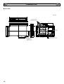
DIMENSIONS
GB
GB
N CE42LH2WP
Unit: mm
989.0
925.4
(WALL MOUNT SCREW)
10 x M6, 1.0 PITCH x 12MM
418.4
1027.0
953.0
930.25
VIEWING AREA(H)
165.9
126.0
418.4
400.0
200.0
100.0
50.8
41.8
523.0
VIEWING AREA(V)
400.0
200.0
Handles x 2
292.0
300.6
546.0
620.0
17.6
178.5
402.9
417.9
ø4.2
(RC RECEIVER)
ø4.2
(LED INDICATOR)
16
Control buttons
43.7
Cables exit terminal cover
GB
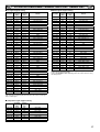
PC/DVI-D/COMPONENT SIGNAL SUPPORT TIMING LIST
N PC signal support timing
Resolution
+RUL]RQWDO
Frequency
N+]
Vertical
Frequency
+]
GB
N DVI-D signal support timing
Remark
Resolution
+RUL]RQWDO
Frequency
N+]
Vertical
Frequency
+]
Remark
720 x 400
31.47
70.09
DOS (VGA)
640 x 480
31.43
59.88
VGA VESA 60Hz
640 x 480
31.43
59.88
VGA VESA 60Hz
640 x 480
37.86
72.81
VGA VESA 72Hz
640 x 480
37.50
75.00
VGA VESA 75Hz
640 x 480
37.5
75
VGA VESA 75Hz
640 x 480
37.86
72.81
VGA VESA 72Hz
640 x 480
34.97
66.6
MAC LC 13"
640 x 480
43.27
85.00
VGA VESA 85Hz
640 x 480
35
66.67
MAC_NORMAL 13"
640 x 480
35.00
66.67
Mac. 13
800 x 600
35.16
56.25
SVGA VESA 56Hz
640 x 480
34.97
66.60
Mac LC 13"
800 x 600
37.88
60.32
SVGA VESA 60Hz
800 x 600
35.16
56.25
SVGA VESA 56Hz
800 x 600
46.875
75
SVGA VESA 75Hz
800 x 600
37.88
60.32
SVGA VESA 60Hz
832 x 624
49.72
74.55
MAC_NORMAL 16"
800 x 600
46.875
75.00
SVGA VESA 75Hz
1024 x 768
48.36
60
XGA VESA 60Hz
800 x 600
34.50
55.38
SVGA
1024 x 768
60.23
75.03
XGA VESA 75Hz
800 x 600
38.00
60.51
SVGA
1024 x 768
56.47
70.07
XGA VESA 70Hz
800 x 600
53.67
85.06
SVGA VESA 85Hz
1024 x 768
60.24
75.08
MAC_NORMAL 19"
832 x 624
49.72
74.55
Mac. 16
1152 x 870
68.68
75.06
MAC_NORMAL 21"
1024 x 768
48.36
60.00
XGA VESA 60Hz
1280 x 1024
63.98
60.02
SXGA VESA 60Hz
1024 x 768
56.47
70.07
XGA VESA 70Hz
720 x 480
31.7
59.94
480p
1024 x 768
60.02
75.03
XGA VESA 75Hz
720 x 480
15.73
59.94
480i
1024 x 768
48.50
60.02
XGA
768 x 575
31.25
50
575p
1024 x 768
60.31
74.92
XGA
768 x 575
15.63
50
575i
1024 x 768
61.00
75.70
XGA
1280 x 720
37.5
50
720p - 50Hz
1024 x 768
68.68
85.00
XGA VESA 85Hz
1280 x 720
45
60
720p - 60Hz
1024 x 768
60.24
75.08
MAC_Normal 19"
1366 x 768
48.36
60
WXGA
1280 x 720
37.5
50.00
720p - 50Hz
1360 x 768
47.7
60
WXGA
1280 x 960
60.00
60.00
SXGA VESA 60Hz
1920 x 1080
28.125
50
1080i - 50Hz
1280 x 1024
79.976
75.025
SXGA VESA 75Hz
1920 x 1080
33.75
60
1080i - 60Hz
1280 x 1024
63.370
60.01
SXGA
1920 x 1080
56.25
50
HDTV 1080p - 50Hz
1280 x 1024
63.34
59.98
SXGA
1920 x 1080
67.5
60
HDTV 1080p - 60Hz
1280 x 1024
63.74
60.01
SXGA
1920 x 1080
27.00
24
HDTV 1080p - 24Hz
1280 x 1024
63.79
60.18
SXGA
1920 x 1080
28.13
25
HDTV 1080p - 25Hz
1280 x 1024
63.90
60.00
SXGA
1920 x 1080
33.75
30
HDTV 1080p - 30Hz
1280 x 1024
81.13
76.107
SXGA
1152 x 900
61.20
65.20
SXGA
1152 x 900
61.85
66.00
SXGA
1152 x 900
71.40
75.60
SXGA
1400 x 1050
65.35
60.12
SXGA +
1400 x 1050
65.12
59.90
SXGA +
MAC_Normal 21"
1152 x 870
68.68
75.06
1280 x 1024
80.00
75.00
Mac II
1600 x 1200
75.00
60.00
UXGA VESA 60Hz
1366 x 768
48.36
60.01
WXGA
1360 x 768
47.73
60.03
WXGA
1920 x 1080
28.125
50.00
1080i - 50Hz
1920 x 1080
33.75
60.00
1080i - 60Hz
Depending on the condition of signals and the type and length of cables, these
signals may not be properly viewed.
To save the XGA Mode 1366 x 768 setting switch the monitor off then on using
the standby button.
The monitor can be automatically adjusted in pc mode when receiving a standard VESA signal. It will be displayed as XGA when the monitor is receiving a
XGA or WXGA signal.
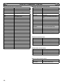
N Component signal support timing
+RUL]RQWDO
Frequency
N+]
Vertical
Frequency
+]
Remark
720 x 480
15.735
60i
SDTV 480i
720 x 576
15.625
50i
SDTV 576i
720 x 480
31.25
60p
SDTV 480p
Resolution
720 x 576
31.25
50p
SDTV 576p
1280 x 720
45.00
60p
HDTV 720p
1280 x 720
37.50
50p
HDTV 720p
1920 x 1080
33.75
60i
HDTV 1080i
1920 x 1080
28.13
50i
HDTV 1080i
17
RS232C COMMAND TABLES
GB
N Functional Execution Command Table
Command
Item
GB
N Image control Read Command Table
Status read command
Item
C00
POWER ON
CR BRIGHT
Status of Brightness.
C01
POWER OFF
CR CONT
Status of Contrast.
C03
POWER ON/ OFF (toggle)
CR COLOR
Status of Color.
C10
Wide toggle
CR TINT
Status of Tint.
C22
Input
CR SHARP
Sharpness.
C24
Wide “Natural” direct
CR WBAL
C25
Wide “Zoom 16:9” direct
Status of White Balance Mode information.
C26
Wide “Title in 16:9” direct
CR WBAL-R
Status of White Balance Red.
C27
Wide “Zoom 14:9” direct
C28
Wide “Title in 14:9” direct
C29
Wide “Full” direct
CR WBAL-G
Status of White Balance Green.
CR WBAL-B
Status of White Balance Blue.
CR NZRED
Status of Noise reduction setting.
CR FILM
Status of Film mode setting.
Status of Image selection.
(The same as PICTURE mode)
C30
Picture
C0F
Wide “Normal” direct
CR IMAGE
C70
AV1 direct
CR DCDI
Status of DCDi setting.
C71
RGB direct
CR ACCACM
Status of ACC/ACM setting.
C72
AV2 RGBHV direct
CR CCS
Status of CCS setting.
C73
AV2 YPbPr direct
CR MPEGNR
Status of MPEG NR setting.
C74
AV3 direct
C75
DVI direct
C76
PC direct
C64
PC Auto adjust
C92
Factory settings
CF PSAVE ON
Power save ON
CF PSAVE OFF
Power save OFF
CF CLOK ON
&KLOGORFN21
CF CLOK OFF
&KLOGORFN2))
CF DEA RMCY
RC inhibition OFF
CF DEA RMCN
RC inhibition ON
N PC Read Command Table
Status read command
Item
CR H-POS
Status of Horizontal position.
CR V-POS
Status of Vertical position.
CR PHASE
Status of PHASE value.
CR CLOCK
Status of CLOCK value.
N Input Read Command Table
Status read command
Item
CR INPUT
Status of Input selection.
CR SOURCE
Status of Input source mode.
CR SYSTEM
Status of system of Input mode.
N Screen Read Command Table
Status read command
CR SCREEN
18
Item
Status of screen size.
(The same of WIDE mode)
GB
RS232C COMMAND TABLES GB
N Time Read Command Table
Status read command
CR PANELH
CR MONH
N UK5 Read Command Table (Basic Command)
Item
Status of accumulated lifetime of panel.
(The same as CR_LAMPH Command)
Status of accumulated lifetime of monitor.
7KHVDPHDV&5B352-+&RPPDQG
N Sound control Read Command Table
Status read command
Item
Command
Item
Note
CR0
Power
On, Standby, power error,
CR1
Input Mode
AV1, AV2, . . . , DVI, PC
CR WIDE
Wide mode
Auto, Normal, Full, . . .
CR PICTURE
Picture mode
Dynamic, Standard, . . .
CR SIGNAL
Signal existence
Signal/No signal
CR CHILD
&KLOGORFN
On/Off
CR PSAVE
Power save
On/Off
Panel usage time
CR VOLUME
Status of volume value.
CRTM
CR MUTE
Status of MUTE.
CR RMC
RC inhibition
On/Off
CR MDL
Model number
Model number
N Setting Read Command Table
Status read command
N Error code Table
Item
CR LANG
Status of Language selection.
CR P-MANE
Status of Power management setting.
CR TILE
Status of Tile mode ON/OFF setting.
CR TILE-HSETS
Status of Tile mode, the number of
Horizontal array.
CR TILE-VSETS
–––
Error code
Note
?
• Receiving the data that cannot be decoded.
• The wrong indication of parameter.
:URQJ¿JXUHGQXPEHURUZURQJZRUGLVLQFOXGHG
000
Normal receiving. (no error)
102
If the command of out of range is directly entered
valuable parameter.
103
No matching with Hardware.
(Command for optional function which is not
equipped)
Status of Tile mode, the number of
Vertical array.
CR TILE-HLOCAT
Status of Tile mode, the number of
Horizontal allocation.
CR TILE-VLOCAT
Status of Tile mode the number of Vertical allocation.
201
If the command of “Out of range” is entered by
inclement or decrements by numeric value.
&57,/(%=/+$'-
Status of Tile mode, the width of bezel
(Horizontal).
301
While capturing the picture, no execution. Wait and
transmit command again.
&57,/(%=/9$'-
Status of Tile mode, the width of bezel
(Vertical).
402
While PIN code is in operation, no execution.
Wait and transmit command again.
CR ONPROG
Status of On Program information.
101
The errors not including above.
CR WINTERMODE
Status of Winter mode Information.
CR PANELPROTECT
Statuses of Panel protect Information.
CR LEDLIGHT
Status of LED light Information.
CR AVAUTOSHUT
Status of AV auto shut OFF Information.
CR CHILDLOCK
6WDWXVHVRI&KLOGORFN,QIRUPDWLRQ
CR RCINHIBITION
Status of RC Inhibit Information.
N Other Read Command Table
Status read command
Item
CR STATUS
Status of the operation of the monitor.
CR SIGNAL
Status of with or without signal.
CR FREEZE
Status of Freeze setting.
CR FANLOCK
6WDWXVHVRIIDQORFNHUURU
CR TEMP
Status of current temperature value.
19
N7RAK/ N7RBK/ N7RPK
6$1<2(OHFWULF&R/WG
INSTALLATION GUIDELINES
CONSIGNES D’INSTALLATION
INSTRUCCIONES DE INSTALACIÓN
INSTALLATIONSRICHTLINIEN
CE42LH2WP
CE42LM6WP
CE42SR2
CE52LH2WP
CE52SR2
CE52SR3
INSTALLATIEHANDLEIDING
WICHTIG
BITTE LESEN SIE DIESE RICHTLINIEN VOR DEM
AUSPACKEN UND DER INSTALLATION.
BELANGRIJK
LEES DEZE HANDLEIDING VOOR HET UITPAKKEN EN
INSTALLEREN.
IMPORTANTE
LEGGERE ATTENTAMENTE LE SEGUENTI ISTRUZIONI
PRIMA DI DISIMBALLARE E INSTALLARE IL PRODOTTO.
English
Français
(P14 ~ 25)
(P26 ~ 37)
Español
Deutsch
POR FAVOR, LEA ESTAS INSTRUCCIONES ANTES DE
PROCEDER AL DESEMBALAJE Y LA INSTALACIÓN.
(P38 ~ 49)
¡IMPORTANTE!
Nederlands
VEUILLEZ LIRE ATTENTIVEMENT CES CONSIGNES AVANT
DE DEBALLER ET D’INSTALLER LE MONITEUR.
(P50 ~ 61)
IMPORTANT
Italiano
PLEASE READ THESE GUIDE LINES PRIOR TO UNPACKING
AND INSTALLATION.
(P62 ~ 73)
IMPORTANT
(P2 ~ 13)
ISTRUZIONI DI INSTALLAZIONE
English
IMPORTANT!!
To All Installers,
This monitor is sealed to IP66 standard. The integrity of
the enclosure MUST NOT be tampered with or breached.
The following guide lines highlight those areas of the
product that require particular care and attention in order
to ensure the integrity of the enclosure.
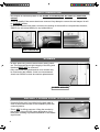
REMOVAL FROM OUTER CARTON
• We strongly advise that 2 ~ 4 PEOPLE handle the monitor when removing it from the carton.
Dropping or bumping the monitor during unpacking can result in damage to the sets integrity and
appearance.
• Please ensure carton top is facing upwards before removing monitor.
%HIRUHUHPRYLQJPRQLWRUIURPFDUWRQZHUHFRPPHQGWKDWWKHPRXQWLQJEUDFNHWLVDWWDFKHGÀUVWWR
avoid any damage during installation.
• Please ensure that both installers grip the monitor as shown in photos below.
To lift and maneuver the monitor, please use the handles provided and support from underside as
illustrated in picture.
IT IS STRONGLY RECOMMENDED
TO HANDLE BY 2 ~ 4 PEOPLE.
Always use the handles to lift the set
ALWAYS SUPPORT THE MONITOR FROM UNDERNEATH
2
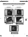
BACK OF MONITOR
LD-NET COVER
SECURITY FIXING POINT
(42 inch model only)
TERMINAL COVER
MAINS LEAD
* This photo is 42 inch model.
• There are labels to inform users that the vents MUST NOT be loosened or removed otherwise the
sealing of the set will be compromised. Adhesive applied to the vent threads provides added seal
security and a visual indication of tampering. In the event that this adhesive sealing is broken when
the set is returned, SANYO can not accept liability for the condition.
• Vent caps can be easily damaged. The set should always be lifted (DO NOT SLIDE) and always
PDNHXVHRIUDLVHGFXVKLRQVXQGHUWKHDOXPLQLXPIUDPHLISODFHGÁDWRQUHDUVLGH
• The vents SHOULD NOT be covered or obstructed.
Please note that caps are easily damaged.
Do not lay monitor with rear side down without proper protection underneath.
EXAMPLE OF VENT
CAP MISSING
3
English
WEATHERPROOF ENCLOSURE VENTILATION
ANTI-TAMPER INK
• Anti-tamper ink has been placed on the screws on the back plate, AV insert and outer back
cabinet.
• This is to identify if the screws have been removed. Any attempt to remove the anti-tamper ink will
be CLEARLY visible.
• In the event that the back plate is removed, the sealing of the set will be compromised, therefore,
SANYO can not accept liability for any related failure.
ANTI-TAMPER INK
SCREWS
$OOEDFNSODWHÀ[LQJVFUHZVXWLOLVHUXEEHUVHDOLQJZDVKHUV7KLVLPSURYHVWKHDLUWLJKWLQWHJULW\RIWKHÀ[LQJDQG
therefore MUST NOT be removed.
2QO\ZDOOPRXQWÀ[LQJDQGWHUPLQDOFRYHUVFUHZVPD\
be removed by the installer. Under no circumstances
should non-SANYO screws be used as replacements.
RUBBER WASHER
SECURITY FIXING POINT (42 inch model only)
$VHFXULW\À[LQJSRLQWLVSURYLGHGRQWKHEDFNSODWHLQ
order to secure the monitor to the installation point with
a security device.
• This is NOT for lifting purposes. Lifting the monitor by
WKHVHFXULW\À[LQJSRLQWZLOOFDXVHGHIRUPDWLRQRIWKH
back plate, resulting in possible breakdown of the weatherproof seal.
4
REAR A.V.SHIELD COVER/TERMINAL COVER
$IWHUFDEOHLQVWDOODWLRQ3/($6(HQVXUHDOOVHDOVDUHFRUUHFWO\ÀWWHGDVVKRZQEHORZSULRUWRUHÀWting the terminal cover and rear A.V.cover. ALLÀ[LQJVFUHZVPXVWEHUHSODFHGDQGWLJKWHQHG
Check point 1
Check point 2
&DEOHVPXVWÀWLQWKHVKDSHRIWKH
recess of the terminal base.
English
Check gasket is in place inside the cover.
Gasket is important to seal cable area.
MAKE SURE CORD FITS IN
THE MOULD SHAPE
GASKET IN THE TERMINAL
COVER
GASKET IN THE RECESS
OF THE TERMINAL BASE
5
MAINS LEAD
• The mains lead is secured to the back plate using a weatherproof cable gland.
Do not loosen the gland as this will impair the weatherproof sealing.
VIEW INSIDE ENCLOSURE
RUBBER WASHER
ADHESIVE TREATMENT
7KHFDELQHWFRUQHUVDUHVHDOHGXVLQJDVSHFLDODGKHVLYHWRPD[LPLVHWKHVHDO
• Sets must be handled with EXTREME care to ensure that this seal is not damaged. Please take
particular care not to drop or bump the set during handling/installation.
COATING MATERIAL
• The steel back plate is protected from corrosion using a polyester powder coating. Good care and
attention must be taken to prevent scratching the surface. Any uncoated metal will corrode potentially affecting the integrity of the enclosure.
• Similarly the same care and attention applies to the aluminum enclosure which is anodised to protect it from corrosion.
CAUSE RUST!!
6
INSTALLING POSITION
When the monitor installed outside, it SHOULD NOT set
in a position where the screen is subjected to direct sun
light.
If it can’t be done, please prepare adequate shading. Direct sun light can cause the screen surface temperature
WRULVHDERYHWKHPD[LPXPRSHUDWLQJUDQJH
This causes a black shadow to appear on the screen,
which will disappear when the screen temperature returns
WRZLWKLQVSHFLÀFDWLRQ
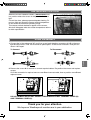
WIRE ASSEMBLY
1. Connect the in-line waterproof AC cord, line up and push together connectors A & B so they are
tight and then twist C until A & B cannot be pulled apart. To disconnect unscrew C and pull connector A & B apart.
To Connect
To Disconnect
C
B
A
English
C
B
A
2. Remove the covers A for access to connect required cables. Re-position the covers and replace
screws.
If LD Net connection is required remove cover B and connect cable, then re-position cover B and
replace screws.
B
B
A
A
DO NOT REMOVE SILICA GEL SACHETS FROM INSIDE LD-NET TERMINAL COVER (B)
AND TERMINAL COVER (A).
Thank you for your attention.
We hope our Weatherproof monitors are to your satisfaction.
7
SAFETY PRECAUTIONS
GB
GB
CAUTION: Please read and retain for your safety. This unit has been designed and manufactured to assure your personal safety, but
LPSURSHUXVHFDQUHVXOWLQSRWHQWLDOHOHFWULFVKRFNRUÀUHKD]DUGV,QRUGHUQRWWRGHIHDWWKHVDIHJXDUGVLQFRUSRUDWHGLQWKLVPRQLWRUREVHUYHWKH
following basic rules for its installation, use and servicing.
Installation and Use
Do not allow anything to rest on the power
cord. Do not locate this LCD monitor where the
cord will be damaged by people walking on it.
Do not RYHUORDGZDOORXWOHWVDQGH[WHQVLRQ
FRUGVDVWKLVFDQUHVXOWLQÀUHRUHOHFWULFVKRFN
A suitable socket outlet must be provided near
to the monitor and shall be easily accessible.
Do not place this LCD monitor near any heat
sources such as radiators, heaters, stoves and other heat-generating
SURGXFWVLQFOXGLQJDPSOLÀHUV
Do not place your LCD monitor on an unstable stand, shelf or table.
Serious injury to an individual, and damage to the LCD monitor may
result if it should fall. Your sales person can recommend an approved
wall mounting kit. A special wall mounting kit is available for this
model.
This LCD monitor should be operated only from the type of power
source indicated on the monitor or as indicated in the Operating Instructions. If you are not sure of the type of power supply, consult your
sales person or your local power company.
For added protection it is strongly recommended that this LCD
monitor has its mains supplied via an approved earth fault protection
device.
WARNING: To prevent injury the LCD monitor must be securely
attached to the wall in accordance with the manufacturers installation
instructions.
IMPORTANT:
This product must be earthed.
This unit is not disconnected from the mains unless the mains lead
is unplugged. The installer must make sure that the waterproof inline
coupler is easily accessible.
This monitor is tested to IP66 standard rating.
This monitor is not protected against temporary or continuous
immersion in liquid.
Do not use immediately after moving the LCD monitor from a low
temperature to a high temperature environment, as this causes conGHQVDWLRQZKLFKPD\UHVXOWLQÀUHHOHFWULFVKRFNRURWKHUKD]DUGV
Before cleaning, unplug the monitor from the wall socket.
Do notPRXQWQHDUDQRSHQÁDPHVRXUFH2SHQÁDPHVPXVWQHYHU
be used near this LCD monitor.
This LCD monitor should not be built in or enclosed in any way, heat
build up will reduce the life of the monitor.
This LCD monitor should have a minimum distance of 5cm away from
the wall and the monitor should have 10cm distance around the top
and sides.
AlwaysPRXQWXVLQJUHFRPPHQGHGDQGVXEVWDQWLDOÀ[WXUHVDQGÀWtings.
The operating temperature range of this monitor is guaranteed 0°C
~ 40°C/32°F ~ 104°F. It is not recommended to install the screen
in direct sunlight without adequate shading, as this will cause the
WHPSHUDWXUHRIWKHSDQHOWRULVHDERYHWKHPD[LPXPVSHFLÀHG
Doing so may cause a black shadow to appear on the screen which
will disappear when the screen temperature returns to within the
VSHFLÀFDWLRQ7KLV´RIFRXUVHµGRHVQRWSURGXFHDQ\KDUPIXOHIIHFWRQ
the lifetime of the monitor.
Do not apply liquid cleaners or aerosol cleaners directly onto the LCD
monitor. Use a damp cloth for cleaning.
ADDITIONAL FOR NORTH AMERICA AND CANADA:
This monitor must NOT be permanently mounted to the building
structure. It must be mounted in such a way that it can be removed
using basic tools.
The power supply cord must NOT be attached to the building surface.
The power supply cord must NOT be routed through walls, ceiling,
ÁRRUVRURWKHUVLPLODURSHQLQJVLQWKHEXLOGLQJVWUXFWXUH
The power supply cord MUST be positioned so as to prevent physical
damage.
Important: (UK only)
THIS PRODUCT MUST BE EARTHED.
7KLVHTXLSPHQWLVÀWWHGZLWKDQDSSURYHGPDLQVOHDGDQGDQ
approved non rewireable UK mains plug. To change a fuse in this
type of plug proceed as follows:
1. Remove the fuse cover and fuse.
2. Fit a new fuse which should be a BS1362 13 Amp A.S.T.A. or
BSI approved type.
3.(QVXUHWKDWWKHIXVHFRYHULVFRUUHFWO\UHÀWWHG
If the fuse cover is lost or damaged the plug must NOT be used
but replaced with a serviceable plug.
,IWKHÀWWHGSOXJLVQRWVXLWDEOHIRU\RXUVRFNHWRXWOHWVLWVKRXOG
EHFXWRIIDQGDQDSSURSULDWHSOXJÀWWHGLQLWVSODFH,IWKHPDLQV
plug contains a fuse, this should have a rating of 13 Amp, ensure
WKHIXVHFRYHULVFRUUHFWO\ÀWWHG,IDSOXJZLWKRXWDIXVHLVXVHG
the fuse at the distribution board should not be greater than 13
Amp.
Note: The severed plug must be destroyed to avoid a possible
VKRFNKD]DUGVKRXOGLWEHLQVHUWHGLQWRD$PSVRFNHWHOVHwhere.
The wires in this mains lead are coloured in accordance with the
following code:
Blue
Brown
Green and Yellow
Neutral
Live
Earth
1. The Blue wire must be connected to the terminal which is
PDUNHGZLWKWKHOHWWHU´1µRUFRORXUHG%/$&.
2. The Brown wire must be connected to the terminal with the
OHWWHU´/µRUFRORXUHG5('
10cm
5cm
10cm
10cm
3. The Green and Yellow wire must be connected to the termiQDOZKLFKLVPDUNHGZLWKWKHOHWWHU´(µRUFRORXUHG*5((1RU
GREEN and YELLOW.
Before replacing the plug cover, make certain that the cord grip is
clamped over the sheath of the lead - not simply over the wires.
Do not attempt to bypass the safety purpose of the grounding
type plug.
7KHUHDUÀQQHGVHFWLRQDURXQGWKHFDELQHWIXQFWLRQVDVDKHDWVLQN
UHPRYLQJKHDWDZD\IURPWKHPRQLWRU7KHH[WHUQDOVXUIDFHRIWKH
FDELQHWÀQQHGDUHDPXVWQRWEHFRYHUHGRUWKHDLUÁRZUHVWULFWHGLQ
anyway by enclosing the LCD monitor.
8
THIS UNIT IS NOT DISCONNECTED FROM THE MAINS UNLESS THE MAINS LEAD IS UNPLUGGED.
THE INSTALLER MUST MAKE SURE THE MAINS LEAD IS
EASILY ACCESSIBLE.
SERVICING
GB
GB
Servicing
Your monitor is fully transistorised and does not contain any user serviceable components.
You must not remove the rear cover of the monitor by yourself. The apparatus is working with high voltages and could damage
objects or even endanger people. Leave all required repair and service jobs to an authorised service technician. He will exclusively
use such spare parts that are complying with the same safety standards as applicable to the original parts. The use of original spare
SDUWVFDQSUHYHQWÀUHVKRFNDQGRWKHUKD]DUGV
8QSOXJWKH/&'PRQLWRUIURPWKHZDOORXWOHWDQGUHIHUVHUYLFLQJWRTXDOLÀHGVHUYLFHSHUVRQQHOXQGHUWKHIROORZLQJ
conditions:
NIf the power cord or plug is damaged.
NIf liquid has been spilt in to the LCD monitor.
NIf the LCD monitor has been dropped or the cabinet has been damaged.
N,IWKH/&'PRQLWRUH[KLELWVDGLVWLQFWFKDQJHLQSHUIRUPDQFH
NIf the LCD monitor does not operate normally by following the operating instructions.
Adjust only those controls that are covered in the operating instructions as improper adjustment of other controls may result in damage.
7KLVZLOORIWHQUHTXLUHH[WHQVLYHZRUNE\DTXDOLÀHGWHFKQLFLDQWRUHVWRUHWKHPRQLWRUWRQRUPDORSHUDWLRQ
Important recycling information.
Your SANYO product is designed and manufactured with high quality materials and components
which can be recycled and reused.
English
This symbol means that electrical and electronic equipment, at their end-of-life, should be disposed of separately.
In the European Union there are separate collection systems for used electrical and electronic
products.
Please help us to conserve the environment we live in!
Note: This symbol mark and recycle system are applied only to EU countries are not applied to
other countries of the world.
Federal Communications Commission Notice
This equipment has been tested and found to comply with the limits for a Class A digital device, pursuant to Part 15 of FCC Rules. These limits
are designed to provide reasonable protection against harmful interference when the equipment is operated in a commercial environment. This
equipment generates, uses, and can radiate radio frequency energy and, if not installed and used in accordance with the instruction manual,
may cause harmful interference to radio communications. Operation of this equipment in a residential area is likely to cause harmful interferHQFHLQZKLFKFDVHWKHXVHUZLOOEHUHTXLUHGWRFRUUHFWWKHLQWHUIHUHQFHDWKLVRZQH[SHQVH
'RQRWPDNHDQ\FKDQJHVRUPRGLÀFDWLRQVWRWKHHTXLSPHQWXQOHVVRWKHUZLVHVSHFLÀHGLQWKHLQVWUXFWLRQV,IVXFKFKDQJHVRUPRGLÀFDWLRQV
should be made, you could be required to stop operation of the equipment.
Canadian Radio Interference Regulations
This Class A digital apparatus meets all requirements of the Canadian ICES-003.
WARNING
This is a Class A product. In a domestic environment this product may cause radio interference in which case the user may be required to take
adequate measures.
9
GB SERVICING
GB
AC Power Cord Requirement
The AC Power Cord supplied with this LCD monitor meets the requirement for use in the country in which you
purchase it.
AC Power Cord for the United States and Canada:
$&3RZHU&RUGXVHGLQWKH8QLWHG6WDWHVDQG&DQDGDLVOLVWHGE\WKH8QGHUZULWHUV/DERUDWRULHV8/DQGFHUWLÀHG
by the Canadian Standard Association (CSA).
GROUND
$&3RZHU&RUGKDVDJURXQGLQJW\SH$&OLQHSOXJ7KLVLVDVDIHW\IHDWXUHWRPDNHVXUHWKDWWKHSOXJZLOOÀWLQWRWKHSRZHURXWOHW
Do not try to defeat this safety feature. Should you be unable to insert the plug into the outlet, contact your electrician.
THE SOCKET-OUTLET SHOULD BE INSTALLED NEAR THE EQUIPMENT AND EASILY ACCESSIBLE
End-User License
The product (meaning the equipment or appliance to which this documentation relates) incorporates Software (the software applications, utilities and modules embedded within the Product) which is owned by Sanyo or its licensors. Before using the product, please read the End-User
License Conditions detailed below. If you do not agree to the terms and conditions of the End-User License, Please do not proceed to use the
Product- repack the Product unused and return it to your supplier together with proof of purchase for a full refund. By using the product, you
agree to be bound by the terms and conditions of the End-User License.
/LFHQVH*UDQW&RQGLWLRQVDQGUHVWULFWLRQV
1.6DQ\RJUDQWV\RXDQRQH[FOXVLYHZRUOGZLGHVXEMHFWWRH[SRUWFRQWUROVQRQWUDQVIHUDEOHH[FHSWDVSHUPLWWHGE\EHORZUR\DOW\IUHH
license to use the Software upon and with the Product.
2. You may not transfer any of your license rights in the Software without the prior written consent of SANYO and if consent is provided then
the Software shall only be transferred in conjunction with the transfer of the Product AND provided that the transferee has read and agreed
to accept the terms and conditions of this license.
3. You must ensure that the copyright, trademark and other protective notices contained in the Software are maintained and not altered or
removed.
4. The Software provided hereunder is copyrighted and licensed (not sold). SANYO especially does not transfer title or and ownership rights
in the Software to you. The Software provided hereunder may contain or be derived from portions of materials provided to SANYO under
license by a third party supplier.
5.([FHSWDVH[SUHVVO\SHUPLWWHGE\VWDWXWH\RXPD\QRW
LXVHWKH6RIWZDUHLQFRQMXQFWLRQZLWKDQ\RWKHUFRPSXWHUKDUGZDUHRWKHUWKDQWKHSURGXFW
LF RS\DOORUSDUWRIWKH6RIWZDUH
LLQFRUSRUDWHDOORUDQ\RIWKH6RIWZDUHLQWRRWKHUSURJUDPVGHYHORSHGE\RURQEHKDOIRI\RXDQGRUXVHGE\\RX
LUHYHUVHHQJLQHHUGHFRPSLOHRUGLVDVVHPEOHWKH6RIWZDUH
LPDNHWKH6RIWZDUHRUDQ\SDUWRILWDYDLODEOHRUSHUPLWLWVUHGLVWULEXWLRQIRUXVHZLWKDQ\FRPSXWHUKDUGZDUHRWKHUWKDQWKH3URGXFWRU
rent, lease, gift, loan, sell, distribute or transfer possession of the whole or any part of the Software.
Termination
This license is effective until terminated. This license will terminate automatically without notice if you fail to comply with any of its provisions.
Disclaimer
1.7KH6RIWZDUHLVWRWKHH[WHQWSHUPLWWHGE\ODZVXSSOLHG´DVLVµDQG6$1<2DQGLWVVXSSOLHUVH[SUHVVO\H[FOXGHDOOZDUUDQWLHVH[SUHVVRU
LPSOLHGLQFOXGLQJEXWQRWOLPLWHGWRZDUUDQWLHVRIVDWLVIDFWRU\TXDOLW\ÀWQHVVIRUSXUSRVHDQGQRQLQIULQJHPHQWVDYHWRWKHH[WHQWWKDWWKH
VDPHDUHQRWFDSDEOHRIH[FOXVLRQDWODZ
2.,QQRFLUFXPVWDQFHVZLOO6$1<2EHOLDEOHIRUDQ\GLUHFWLQGLUHFWFRQVHTXHQWLDORULQFLGHQWDOGDPDJHLQFOXGLQJORVVRISURÀWVEXVLQHVV
interruption, loss of data or the cost of procurement of substitute goods, technology or services) arising out of the use or the inability to use
WKH6RIWZDUHVDYHWRWKHH[WHQWWKDWVXFKOLDELOLW\LVQRWFDSDEOHRIH[FOXVLRQDWODZ
General
1. This End-User License will be governed by laws of England and the User may only bring claims in the English Courts and SANYO shall be
entitled to bring a claim in the courts of any jurisdiction.
2. This End-User License is governed by the laws of the State of California. The End-User and Sanyo agree that any action to enforce or
interpret the terms of this End-User License shall be brought only in the appropriate state or federal court located in Los Angeles County,
&DOLIRUQLD7KH(QG8VHUDQG6DQ\RKHUHE\VXEPLWWRWKHH[FOXVLYHMXULVGLFWLRQDQGYHQXHRIVXFKFRXUW
3. The above terms and conditions supersede any prior agreement, oral or written, between you and SANYO relating to the Software.
10
INSTALLATION
GB
GB
Step: 1 Mains Connection
N&RQQHFWWKHGLVSOD\XQLWWR9*$%1&DQG6FDUWFRQnector as required.
LD-Net
7KLVÀJXUHLVLQFKPRGHO
2. Connect the power cord of the LCD monitor to a suitable wall
outlet.
As this product does not have a mains On/Off switch, please
ensure your mains plug is easily accessible.
The LCD monitor is prepared for a mains voltage AC100 ~ 240V,
+]+]7RFRPSOHWHO\VZLWFKRIIWKHPDLQVRUZKHQWKH
GLVSOD\XQLWLVQRWWREHXVHGIRUDQH[WHQGHGSHULRGRIWLPHLWLV
advisable to disconnect the power cord from the power outlet.
AC Mai
ns
Outlet
4. AV3
Composite (CVBS) signal input.
AV3-OUT can be used to output the incoming AV3 signal to the
other monitor.
5. DVI-D (Digital Video Interface)
DVI-D supports a large range of resolutions as shown in the INSTRUCTION MANUAL on page 17.
6. PC connection
PC input (PC-IN D-SUB). This input supports a large range of resolutions as shown in the INSTRUCTION MANUAL page 17. Audio
can be connected via the 3.5mm PC-AUDIO IN.
English
1. Connect the in-line power connector to the Mains Inlet as shown
above.
7. External Speaker
Output the audio signal from AV1, AV2, AV3, PC and DVI.
The speaker impedance is 8 ohms.
Please use the correct mains lead supplied with the set for your
area.
3. Warning: To prevent injury, the unit must be securely attached to
the wall in accordance with the installation instructions.
WARNING! High voltages are used in the
RSHUDWLRQRIWKLVVHW5HIHUVHUYLFHWRTXDOLÀHG
service personnel.
Step: 2 Connections
8. AV2 / DVI AUDIO IN
Connect the audio output (stereo) from a computer or video equipment connected AV2 or DVI.
NINPUT selection
To switch either AV1, RGB, AV2, AV3, PC, DVI or Network by pressing
the INPUT button on your remote control repeatedly.
1. AV1
SCART connection/CVBS/RGB/S-VIDEO.
2. RGB
TTL input (5V RGB signals) into SCART terminal.
<3E3U5*%+9FRQQHFWLRQ$9
Choose Y, Pb, Pr or RGB H/V connection by selecting AV2 Setting
in Set up menu (refer to the INSTRUCTION MANUAL on page 10).
You can connect your DVD player to the Y, Pb, Pr terminals instead
RIXVLQJDVFDUWOHDG7KLVFDQVXSSRUWKLJKGHÀQLWLRQLQDQDORJXH
component form. RGB H/V can be used as a PC input via the BNC
terminals. Both options support a large range of resolutions (refer
to the INSTRUCTION MANUAL on page 17). AV2-OUT can be used
to output the incoming AV2 signal to the other monitor.
9. Monitor Audio OUT
7KLVWHUPLQDOVRXWSXWÀ[HGOHYHOIURP$8',2,1
10. RS232C IN/OUT
When the monitor is controlled by a computer, connect to this jack
with serial control cable.
You can connect to another monitor with RS232C OUT.
:KHQ\RXFRQQHFW3&ZLWK56&VHOHFW´21µDW1HWZRUN
standby in Installation mode.
,ILWLVVHOHFWHG´2))µ56&WHUPLQDOVGRQRWIXQFWLRQDO$OVR
VHOHFWSXVKEXWWRQWR´6(5,$/32$57µ
11
GB INSTALLATION
GB
Remote control
Input
Standby
To switch input source from AV1, RGB, AV2, AV3,
PC, DVI or Network mode.
To switch the monitor on and off. Also, refer to the
INSTRUCTION MANUAL on page 8.
Recall
Wide
To select the screen mode Full, Full All, Zoom
16:9, Title in 16:9, Zoom 14:9, Title in 14:9,
Normal or Natural wide.
Refer to the INSTRUCTION MANUAL on page 12.
Menu
7RHQWHUDQGH[LWWKHPDLQPHQXDQGVXEPHQX
To display input selection information and the Time
set.
You can also select colour systems in AV1/AV3
mode as follows: AUTO í PAL í SECAM í
NTSC í NTSC4.43 í PAL M í PAL N.
Auto PC
It can also be automatically adjusted in PC mode
by pressing this button for twice .
Back
Used to return to the previous menu.
Level Up/Down
To adjust the sound volume level or enter sub
menus.
F/OK
7RFRQÀUPWKHLQLWLDOVHWWLQJLQWKHPHQX
Picture mode selector
Press the button repeatedly to select the following picture mode.
Personal - Personal preference mode.
Standard - Normal viewing mode.
Dynamic - Suitable for brightly lit rooms.
Soft - Low contrast setting
Eco - Suitable for dimly lit rooms and gives a cinema-like effect.
)UHH]H
To switch picture still on or off.
Green
Press this button for more than 5 seconds, installation mode will appear.
Remote control battery installation
Up and Down
7RVHOHFWWKHQH[WRUSUHYLRXVLWHP
Sound Mute
To mute the sound from the speakers.
The sound changes as follows: Normal
Mute.
volume
Bass Expander
To get an emphasised bass sound ON or OFF.
TXT/TV
7RVHOHFW7HOHWH[WPRGH
Main/Sub Picture Swap
To swap Main and Sub picture.
ON/OFF
To switch OFF í PIP(1) í PIP(2) í POP mode
in turn.
Refer to the INSTRUCTION MANUAL on page 13.
FOR EU USERS
The symbol mark and recycling systems described below apply to EU
countries and do not apply to countries in other areas of the world.
Your SANYO product is designed and manufactured with high quality
materials and components which can be recycled and/or reused.
The symbol mark means that electrical and electronic equipment,
batteries and accumulators, at their end-of-life, should be disposed of
separately from your household waste.
Note:
If a chemical symbol is printed beneath the symbol mark, this chemical symbol means that the battery or accumulator contains a heavy
metal at a certain concentration. This will be indicated as follows: Hg:
mercury, Cd: cadmium, Pb: lead
In the European Union there are separate collection systems for used
electrical and electronic equipment, batteries and accumulators.
Please, dispose of them correctly at your local community waste collection/recycling centre.
,QVWDOOWZR´$$µYROWEDWWHULHVVRWKDWWKH´µDQG´²µPDUNVRQWKH
EDWWHULHVPDWFKWKH´µDQG´²µPDUNVLQVLGHWKHXQLWLQWRWKHUHPRWH
control handset.
12
Please, help us to conserve the environment we live in!
INSTALLATION GB
GB
Controls and Menus
Menu Operation
Many of your monitors functions are controlled through the menu
function, using the remote control.
MENU
Picture
Sound
q
Time
Current Weekday
Current Time
1 - 20
Schedule
Weekday
Time
Power On / Power Off
Action
On Program
AV1 / RGB / AV2 / AV3 / PC / DVI / Network
On / Off
Active
Setup
Menu Setup
Language / H/V-Position / Duration / Transparence
PIP / POP Setup
PIP/POP Mode / Main/Sub Source / PIP Position
Initial Settings
Western / Eastern / Russian / Arabic / Farsi
Text Language
Tile Mode Active / H/V_Sets / H/V Location / Bezel H/V Adjustment
Tile Mode
AV2 Setting
RGBHV / YPbPr
XGA / WXGA 1366x768
XGA Mode
PC Power save
On / Off
w
å The LCD display has a Standby light to show there is power.
Switching into/from standby mode
The Standby mode is used for switching the LCD monitor off for short
periods of time. In standby mode the monitor is switched off but is still
receiving mains power.
To turn the monitor into standby mode, press the button.
The blue power indicator illuminates more brightly.
L
o turn the monitor ON from standby mode, press the button
T
again.
L
Brightness
Contrast
Color
Tint (only if NTSC equipment is detected)
Sharpness
White Tone
White Tone / R / G / B
Advanced Setting
DCDi / ACC/ACM / CCS / DNR / MPEG NR / Film Mode
Treble
Bass
Balance
On / Off
Bass Expander
PC Adj.
Auto Adjust
H-Position
V-Position
Clock
Phase
During menu operation the bottom of the on screen display will show
which controls can be used for menu navigation.
Press the MENU button to enter the main menu. Whenever main
menu is accessed initially, PICTURE will be the default selection.
A sub menu is selected using the or button and pressing
the or button when the required sub menu is highlighted.
:KHQ\RXKDYHÀQLVKHG\RXFDQSUHVVWKHBACK button to return to
the previous menu, press the MENU buttonWRH[LWWKHPHQXRSHUDWLRQ
English
,I\RXÀQGWKHSRZHULQGLFDWRUÁDVKLQJGLVFRQQHFW
power cord from the power outlet and contact our
Service desk.
This warning is a sign to let you know that the
power protection function of this TV set is now
operating.
Picture menu
ç Control buttons (bottom corner of back cover)
1. Press the MENU button. PICTURE will be the default selection.
Press the or button to enter.
6HWWKHSLFWXUHVHWWLQJVIRU\RXU´personalµSUHIHUHQFH
Menu button: Used to display or cancel main menu.
Input/
button: Switch between AV1, RGB, AV2, AV3, PC , DVI
or Network mode. It is also used to provide sub
menu selection from the Main Menu.
or buttons: provide up and down adjustments.
button: To switch to standby mode (to switch off completely
disconnect the monitor from the power supply).
2. Use the or button to select eg. Brightness and the or
button to adjust levels.
N White Tone
May be used to adjust the color tone of the picture. Use the or
button to select White Tone and press the or button
to enter the sub menu. You can select Personal, Cool, Standard or
Warm settings by using the or button. To adjust the color
tone of the picture by using the or button to select Red(R),
Green(G) or Blue(B) and the or button to adjust levels.
These settings will be stored in personal mode automatically.
13