1
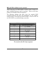
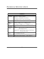
DES-1008D
8-Port 10/100Mbps
Dual Speed Ethernet Switch
User’s Guide
Rev. 02 (Mar. 2000)
6012-9600011
Printed In Taiwan
RECYCLABLE
i
LIMITED WARRANTY
D-Link Systems, Inc. (“D-Link”) provides this limited warranty for its
product only to the person or entity who originally purchased the product
from D-Link or its authorized reseller or distributor.
Limited Hardware Warranty: D-Link warrants that the hardware
portion of the D-Link products described below (“Hardware”) will be free
from material defects in workmanship and materials from the date of
original retail purchase of the Hardware, for the period set forth below
applicable to the product type (“Warranty Period”) if the Hardware is used
and serviced in accordance with applicable documentation; provided that a
completed Registration Card is returned to an Authorized D-Link Service
Office within ninety (90) days after the date of original retail purchase of the
Hardware. If a completed Registration Card is not received by an
authorized D-Link Service Office within such ninety (90) period, then the
Warranty Period shall be ninety (90) days from the date of purchase.
Product Type
Warranty Period
Product (excluding power supplies and
fans), if purchased and delivered in the fifty
(50) United States, or the District of
Columbia (“USA”)
As long as the
original purchaser
still owns the
product
Product purchased or delivered outside the USA
One (1) Year
Power Supplies and Fans
One (1) Year
Spare parts and spare kits
Ninety (90) days
D-Link’s sole obligation shall be to repair or replace the defective Hardware
at no charge to the original owner. Such repair or replacement will be
rendered by D-Link at an Authorized D-Link Service Office.
The
replacement Hardware need not be new or of an identical make, model or
part; D-Link may in its discretion may replace the defective Hardware (or
any part thereof) with any reconditioned product that D-Link reasonably
determines is substantially equivalent (or superior) in all material respects
to the defective Hardware. The Warranty Period shall extend for an
additional ninety (90) days after any repaired or replaced Hardware is
delivered. If a material defect is incapable of correction, or if D-Link
determines in its sole discretion that it is not practical to repair or replace
the defective Hardware, the price paid by the original purchaser for the
defective Hardware will be refunded by D-Link upon return to D-Link of the
defective Hardware. All Hardware (or part thereof) that is replaced by DLink, or for which the purchase price is refunded, shall become the property
of D-Link upon replacement or refund.
Limited Software Warranty: D-Link warrants that the software portion
of the product (“Software”) will substantially conform to D-Link’s then
current functional specifications for the Software, as set forth in the
applicable documentation, from the date of original delivery of the Software
for a period of ninety (90) days (“Warranty Period”), if the Software is
properly installed on approved hardware and operated as contemplated in
its documentation. D-Link further warrants that, during the Warranty
Period, the magnetic media on which D-Link delivers the Software will be
free of physical defects. D-Link’s sole obligation shall be to replace the nonconforming Software (or defective media) with software that substantially
conforms to D-Link’s functional specifications for the Software. Except as
otherwise agreed by D-Link in writing, the replacement Software is
provided only to the original licensee, and is subject to the terms and
conditions of the license granted by D-Link for the Software. The Warranty
Period shall extend for an additional ninety (90) days after any replacement
Software is delivered. If a material non-conformance is incapable of
correction, or if D-Link determines in its sole discretion that it is not
practical to replace the non-conforming Software, the price paid by the
original licensee for the non-conforming Software will be refunded by DLink; provided that the non-conforming Software (and all copies thereof) is
first returned to D-Link. The license granted respecting any Software for
which a refund is given automatically terminates.
What You Must Do For Warranty Service:
Registration Card. The Registration Card provided at the back of this
manual must be completed and returned to an Authorized D-Link Service
Office for each D-Link product within ninety (90) days after the product is
purchased and/or licensed. The addresses/telephone/fax list of the nearest
Authorized D-Link Service Office is provided in the back of this manual.
FAILURE TO PROPERLY COMPLETE AND TIMELY RETURN THE
iii
REGISTRATION CARD MAY AFFECT THE WARRANTY FOR THIS
PRODUCT.
Submitting A Claim. Any claim under this limited warranty must be
submitted in writing before the end of the Warranty Period to an Authorized
D-Link Service Office. The claim must include a written description of the
Hardware defect or Software nonconformance in sufficient detail to allow DLink to confirm the same. The original product owner must obtain a Return
Material Authorization (RMA) number from the Authorized D-Link Service
Office and, if requested, provide written proof of purchase of the product
(such as a copy of the dated purchase invoice for the product) before the
warranty service is provided. After an RMA number is issued, the defective
product must be packaged securely in the original or other suitable shipping
package to ensure that it will not be damaged in transit, and the RMA
number must be prominently marked on the outside of the package. The
packaged product shall be insured and shipped to D-Link, 53 Discovery
Drive, Irvine CA 92618, with all shipping costs prepaid. D-Link may reject
or return any product that is not packaged and shipped in strict compliance
with the foregoing requirements, or for which an RMA number is not visible
from the outside of the package. The product owner agrees to pay D-Link’s
reasonable handling and return shipping charges for any product that is not
packaged and shipped in accordance with the foregoing requirements, or
that is determined by D-Link not to be defective or non-conforming.
What Is Not Covered:
This limited warranty provided by D-Link does not cover:
Products that have been subjected to abuse, accident, alteration,
modification, tampering, negligence, misuse, faulty installation, lack of
reasonable care, repair or service in any way that is not contemplated in the
documentation for the product, or if the model or serial number has been
altered, tampered with, defaced or removed;
Initial installation, installation and removal of the product for repair, and
shipping costs;
Operational adjustments covered in the operating manual for the product,
and normal maintenance;
Damage that occurs in shipment, due to act of God, failures due to power
surge, and cosmetic damage; and
Any hardware, software, firmware or other products or services provided by
anyone other tha n D-Link.
Disclaimer of Other Warranties: EXCEPT FOR THE LIMITED
WARRANTY SPECIFIED HEREIN, THE PRODUCT IS PROVIDED “ASIS” WITHOUT ANY WARRANTY OF ANY KIND INCLUDING, WITHOUT
LIMITATION, ANY WARRANTY OF MERCHANTABILITY, FITNESS
FOR A PARTICULAR PURPOSE AND NON-INFRINGEMENT. IF ANY
IMPLIED WARRANTY CANNOT BE DISCLAIMED IN ANY TERRITORY
WHERE A PRODUCT IS SOLD, THE DURATION OF SUCH IMPLIED
WARRANTY SHALL BE LIMITED TO NINETY (90) DAYS. EXCEPT AS
EXPRESSLY COVERED UNDER THE LIMITED WARRANTY PROVIDED
HEREIN, THE ENTIRE RISK AS TO THE QUALITY, SELECTION AND
PERFORMANCE OF THE PRODUCT IS WITH THE PURCHASER OF
THE PRODUCT.
Limitation of Liability: TO THE MAXIMUM EXTENT PERMITTED BY
LAW, D-LINK IS NOT LIABLE UNDER ANY CONTRACT, NEGLIGENCE,
STRICT LIABILITY OR OTHER LEGAL OR EQUITABLE THEORY FOR
ANY LOSS OF USE OF THE PRODUCT, INCONVENIENCE OR DAMAGES
OF ANY CHARACTER, WHETHER DIRECT, SPECIAL, INCIDENTAL OR
CONSEQUENTIAL (INCLUDING, BUT NOT LIMITED TO, DAMAGES
FOR LOSS OF GOODWILL, WORK STOPPAGE, COMPUTER FAILURE
OR MALFUNCTION, LOSS OF INFORMATION OR DATA CONTAINED
IN, STORED ON, OR INTEGRATED WITH ANY PRODUCT RETURNED
TO D-LINK FOR WARRANTY SERVICE) RESULTING FROM THE USE
OF THE PRODUCT, RELATING TO WARRANTY SERVICE, OR ARISING
OUT OF ANY BREACH OF THIS LIMITED WARRANTY, EVEN IF DLINK HAS BEEN ADVISED OF THE POSSIBILITY OF SUCH
DAMAGES. THE SOLE REMEDY FOR A BREACH OF THE FOREGOING
LIMITED WARRANTY IS REPAIR, REPLACEMENT OR REFUND OF
THE DEFECTIVE OR NON-CONFORMING PRODUCT.
GOVERNING LAW: This Limited Warranty shall be governed by the laws
of the state of California.
Some states do not allow exclusion or limitation of incidental or consequential
damages, or limitations on how long an implied warranty lasts, so the foregoing
limitations and exclusions may not apply. This limited warranty provides
v
specific legal rights and the product owner may also have other rights which
vary from state to state.
FCC Warning
This equipment has been tested and found to comply with the
regulations for a Class B digital device, pursuant to Part 15 of the FCC
Rules. These limits are designed to provide reasonable protection
against harmful interference when the equipment is operated in a
commercial environment. This equipment generates, uses, and can
radiate radio frequency energy and, if not installed and used in
accordance with this user’s guide, may cause harmful interference to
radio communications. Operation of this equipment in a residential
area is likely to cause harmful interference, in which case the user will
be required to correct the interference at his own expense.
CE Mark Warning
This is a Class B product. In a domestic environment, this product
may cause radio interference, in which case the user may be required
to take adequate measures.
VCCI Mark Warning
vii
TABLE
OF
C ONTENTS
ABOUT THIS GUIDE........................................................................1
P URPOSE ..............................................................................................1
OVERVIEW OF THIS USER’S GUIDE ...........................................................1
INTRODUCTION ..............................................................................2
FAST ETHERNET T ECHNOLOGY ................................................................2
SWITCHING T ECHNOLOGY .......................................................................2
FEATURES ............................................................................................4
UNPACKING ..........................................................................................6
SETUP ..................................................................................................6
IDENTIFYING EXTERNAL COMPONENTS...............................7
FRONT P ANEL .......................................................................................7
LED I NDICATORS ..................................................................................7
REAR P ANEL .........................................................................................8
CONNECTING THE DES -1008D...................................................10
PC TO DES-1008D..............................................................................10
HUB TO DES-1008D............................................................................10
A. 10BASE-T Hub............................................................................11
B. 100BASE-TX Hub........................................................................11
HUB WITHOUT UPLINK (MDI-II) PORT....................................................11
A. Using straight cable.....................................................................11
B. Using crossover cable..................................................................11
DES-1008D TO SWITCH (OTHER DEVICES)...............................................11
A. Using straight cable.....................................................................12
B. Using crossover cable..................................................................12
P ORT SPEED & DUPLEX MODE ..............................................................12
RJ-45 PIN SPECIFICATION..........................................................13
TECHNICAL SPECIFICATIONS .................................................15
A BOUT T HIS G U I D E
Congratulations on your purchase of the DES-1008D. This device
integrates 100Mbps Fast Ethernet and 10Mbps Ethernet network
capabilities in a highly flexible desktop package.
Purpose
The purpose of this manual is to show you how to install and
configure your DES-1008D.
Overview of this User’s Guide
? Chapter 1, Introduction. Describes the DES-1008D and its features.
? Chapter 2, Unpacking and Setup. Helps you get started with the
basic installation of the DES-1008D.
? Chapter 3, Identifying External Components. Describes the front
panel, rear panel and LED indicators of the DES-1008D.
? Chapter 4, Connecting the DES-1008D. Tells how you can connect
the DES-1008D to your Ethernet network.
? Appendix A, Technical Specifications. Lists the technical (general,
physical and environmental, and performance) specifications of the
DES-1008D.
? Appendix B, RJ-45 Pin Specification. Describes the RJ-45
receptacle/connector and the straight and crossover cable connector.
1
h
IN T R O D U C T I O N
This chapter describes the features of the DES-1008D and some
background information about Ethernet/Fast Ethernet switching
technology.
Fast Ethernet Technology
The growing importance of LANs and the increasing complexity of
desktop computing applications are fueling the need for high
performance networks. A number of high-speed LAN technologies
have been proposed to provide greater bandwidth and improve
client/server response times. Among them, 100BASE-T (Fast
Ethernet) provides a non-disruptive, smooth evolution from the
current 10BASE-T technology. The non-disruptive and smooth
evolution nature, and the dominating potential market base, virtually
guarantee cost effective and high performance Fast Ethernet solutions
in the years to come.
100Mbps Fast Ethernet is a new standard specified by the IEEE 802.3
LAN committee. It is an extension of the 10Mbps Ethernet standard
with the ability to transmit and receive data at 100Mbps, while
maintaining the CSMA/CD Ethernet protocol. Since the 100Mbps
Fast Ethernet is compatible with all other 10Mbps Ethernet
environments, it provides a straightforward upgrade and takes
advantage of the existing investment in hardware, software, and
personnel training.
Switching Technology
Another approach to pushing beyond the limits of Ethernet technology
is the development of switching technology. A switch bridges
2
Ethernet packets at the MAC address level of the Ethernet protocol
transmitting among connected Ethernet or Fast Ethernet LAN
segments.
Switching is a cost-effective way of increasing the total network
capacity available to users on a local area network. A switch increases
capacity and decreases network loading by dividing a local area
network into different segments, which don’t compete with each other
for network transmission capacity.
The DES-1008D acts as a high-speed selective bridge between the
individual segments. The DES-1008D, without interfering with any
other segments, automatically forwards traffic that needs to go from
one segment to another. By doing this the total network capacity is
multiplied, while still maintaining the same network cabling and
adapter cards.
For Fast Ethernet networks, a DES-1008D is an effective way of
eliminating problems of chaining hubs beyond the “two-repeater
limit.” A DES-1008D can be used to split parts of the network into
different collision domains, making it possible to expand your Fast
Ethernet network beyond the 205-meter network diameter limit for
100BASE-TX networks. DES-1008Ds supporting both traditional
10Mbps Ethernet and 100Mbps Fast Ethernet are also ideal for
bridging between the existing 10Mbps networks and the new
100Mbps networks.
Switching LAN technology is a marked improvement over the
previous generation of network bridges, which were characterized by
higher latencies. Routers have also been used to segment local area
networks, but the cost of a router, the setup and maintenance required
make routers relatively impractical. Today switches are an ideal
solution to most kinds of local area network congestion problems.
3
h
Features
The DES-1008D was designed for easy installation and high
performance in an environment where traffic on the network and the
number of users increase continuously.
The DES-1008D with its small, compact size was specifically
designed for small to middle workgroups. The DES-1008D can be
installed where space is limited; moreover, the DES-1008D provides
immediate access to a rapidly growing network through a wide range
of functions.
The DES-1008D is ideal for deployment with multiple high-speed
servers for shared bandwidth 10Mbps or 100Mbps workgroups. With
the highest bandwidth 200Mbps (100Mbps full-duplex mode), any
port can provide workstations with a congestion-free data pipe for
simultaneous access to the server.
The DES-1008D is expandable by cascading two or more DES1008Ds together. As all ports support 200Mbps, the DES-1008D can
be cascaded from any port and to any number of DES-1008Ds.
The DES-1008D is a perfect choice for sites planning to upgrade to
Fast Ethernet in the future. Ethernet workgroups can connect to the
DES-1008D now, and you can change adapters and hubs anytime later
without needing to change the DES-1008Ds or reconfigure the
network.
The DES-1008D combines dynamic memory allocation with storeand-forward switching to ensure that the buffer is effectively allocated
for each port, while controlling the data flow between the transmit and
receive nodes to guarantee against all possible packet loss.
The DES-1008D is a managed 10/100 Fast Ethernet switch that offers
solutions in accelerating small Ethernet workgroup bandwidth. Other
key features are:
4
?? Uplink/ MDI-II (media dependent interface) port for uplink to
another switch, hub or repeater.
?? Store and forward switching scheme capability. As the result of
complete frame checking and error frame filtering, this scheme
prevents error packages from transmitting among segments.
?? NWay Auto-negotiation for any port. This allows for autosensing of speed (10/100Mbps) thereby providing you with
automatic and flexible solutions in your network connections.
?? Flow control for any port. This minimizes dropped packets by
sending out collision signals when the port’s receiving buffer is
full. Note that flow control is only available in half duplex
mode.
?? Data forwarding rate per port is at wire-speed for 100Mbps
speed.
?? Data forwarding rate per port is at wire-speed for 10Mbps
speed.
?? Data filtering rate eliminates all error packets, runts, etc., per
port at wire-speed for 100Mbps speed.
?? Data filtering rate eliminates all error packets, runts, etc., per
port at wire-speed for 10Mbps speed.
?? 8K MAC address entries table per device for the DES-1008D.
?? 256 KB RAM buffer per device for the DES-1008D.
?? Network looped detecting.
5
h
Unpacking and Setup
This chapter provides unpacking and setup information for the
DES-1008D.
Unpacking
Open the box and carefully unpacks its contents. The box should
contain the following items:
? One DES-1008D
? One external power adapter
? This User’s Guide.
If any item is found missing or damaged, please contact your local
reseller for replacement.
Setup
The setup for the DES-1008D can be performed using the following
steps:
?? The surface must support at least 1.5 Kg for the DES-1008D.
?? The power outlet should be within 1.82 meters (6 feet) of the
DES-1008D.
?? Visually inspect the DC power jack and make sure that it is fully
secured to the power adapter.
?? Make sure that there is proper heat dissipation from and
adequate ventilation around the DES-1008D. Do not place
heavy objects on the DES-1008D.
6
IDENTIFYING E XTERNAL C OMPONENTS
This section identifies all the major external components of the
DES-1008D. Both the front and rear panels are shown followed by
a description of each panel feature. The indicator panel is
described in detail in the next chapter.
Front Panel
The figure below shows the front panel of the DES-1008D.
? LED Indicator Panel
Refer to the LED Indicator section for detailed information about
each of the DES-1008D’s LED indicators.
LED Indicators
Power Indicator (PWR)
This indicator lights green when the hub is receiving power,
otherwise, it is off.
Loop Detect (LOOP)
When this indicator lights amber, it means that there is a loop
detected, then the network needs to be re-configuration.
7
h
Full-Duplex/Collision (Full-Duplex/Collision)
This LED indicator lights green when a respective port is in full
duplex (FDX) mode. Otherwise, it is blinking when collisions are
occurring on the respective port.
100M Link/Activity, 10M Link/Activity (100M LINK/ACT (green),
10LINK/ACT(amber))
This indicator lights green when the port is connected to a 100Mbps
Fast Ethernet station, if the indicator blinking green will be
transmission or received data on the 100Mbps network. Otherwise, if
the indicator light amber when the port is connected to a 10Mbps
Ethernet station, if the indicator blinking amber will be transmission
or received data on the 10Mbps network.
Rear Panel
? DC Power Jack: Power is supplied through an external AC power
adapter. Check the technical specification section for information
about the AC power input voltage.
Since the DES-1008D does not include a power switch, plugging its
power adapter into a power outlet will immediately power it on.
8
? MDI-X Jacks: Use these jacks to connect stations to the hub. These
are MDI-X (Medium-Dependent Interface, Cross-wired) jacks,
which mean, you can use ordinary straight-through twisted-pair
cables to connect user machines and servers to the hub through
them. If you need to connect another device with an MDI-X jack,
such as another hub or an Ethernet switch, you should use a
crossover cable, or make the connection using the MDI-X jack
(described below).
? Uplink Jack(s) (MDI-II): Use this jack to connect stations to the
hub. This is an MDI-II (Medium-dependent Interface, straightwired) jack, which means you can connect the hub to a device with
an MDI-X port using an ordinary straight-through cable, making a
crossover cable unnecessary.
9
h
C ONNECTING T HE DES-1008D
This chapter describes how to connect the DES-1008D to your Fast
Ethernet network. In each of the following figures, the DES-1008D is
shown.
PC to DES-1008D
A PC can be connected to DES-1008D via a two-pair Category 3, 4, 5
UTP/STP straight cable. The PC (equipped with a RJ-45 10/100Mbps
phone jack) can be connected to any of the 8 ports (1x - 8x).
The LED indicators for PC connection depend on the LAN card’s
capabilities. If LED indicators are not lit after making a proper
connection, check the PC LAN card, the cable and the DES-1008D
conditions and connections.
The following are LED indicator possibilities for a PC to DES-1008D
connection:
1.
The “100LINK/ACT,10LINK/ACT” LED indicator lights
green for hookup to 100Mbps speed or light amber for
hookup to 10Mbps speed.
2.
The “Full-Duplex/Collision” LED indicator depends upon
LAN card capabilities for full duplex or half duplex.
Hub to DES-1008D
A hub (10 or 100BASE-TX) can be connected to the DES-1008D via
a two-pair Category 3, 4, 5 UTP/STP straight cables. The connection
is accomplished from the hub uplink (MDI-II) port to any of the DES1008D (MDI-X) ports: 1x - 8x for the DES-1008D.
10
A. 10BASE-T Hub
For a 10BASE-T hub, the DES-1008D LED indicators should light up
as the following:
“Full-Duplex/Collision” indicator is OFF.
“100LINK/ACT,10LINK/ACT LED” indicator is light amber.
B. 100BASE-TX Hub
For a 100BASE-TX hub, the DES-1008D LED indicators should light
up as the following:
“Full-Duplex/Collision” LED indicator is OFF.
“100LINK/ACT,10LINK/ACT” LED indicator is light green.
Hub without Uplink (MDI-II) port
If a hub is not equipped with an uplink (M DI-II) port, connection can
be made using either straight cable or crossover cable.
A. Using straight cable
When using straight cable, the connection can be made from the
uplink (MDI-II) port of the DES-1008D to any port of the hub.
B. Using crossover cable
When using crossover cable, the connection can be made from any
(MDI-X) ports of the DES-1008D to any port of the Hub.
DES-1008D to switch (other devices)
The DES-1008D can be connected to another switch or other devices
(routers, bridges, etc.) via a two-pair Category 3, 4, 5 UTP/STP
straight or crossover cable.
11
h
A. Using straight cable
When using straight cable, this is done from the uplink (MDI-II) port
of the DES-1008D (DES-1008D A) to any of the 10Mbps or 100Mbps
(MDI-X) port of the other switch (switch B) or other devices.
B. Using crossover cable
When using crossover cable, this is done from any (MDI-X) port of
the DES-1008D (DES-1008D A) to any of the 10Mbps, 100Mbps
(MDI-X) port of the other switch (swit ch B) or other devices.
1. The “100LINK/ACT,10LINK/ACT” LED indicator light
green for hookup to 100Mbps speed or light amber for
hookup to 10Mbps speed.
2. The “Full-Duplex/Collision” LED indicator depends upon LAN
card capabilities for full-duplex or half-duplex
Port Speed & Duplex Mode
After plugging the selected cable to a specific port, the system uses
auto-negotiation to determine the transmission mode for any new
twisted-pair connection:
If the attached device does not support auto-negotiation or has
auto-negotiation disabled, an auto-sensing process is initiated to
select the speed and set the duplex mode to half-duplex.
12
RJ-45 P IN S PECIFICATION
When connecting your DES-1008D to another switch, a bridge or a
hub, a modified crossover cable is necessary. Please review these
products for matching cable pin assignment.
The following diagram and tables show the standard RJ-45
receptacle/connector and their pin assignments for the switch-tonetwork adapter card connection, and the straight / crossover cable for
the DES-1008D-to-switch/hub/bridge connection.
RJ-45 Connector pin assignment
Contact
Media Direct Interface Signal
1
TX + (transmit)
2
TX - (transmit)
3
Rx + (receive)
4
Not used
5
Not used
6
Rx - (receive)
7
Not used
8
Not used
The standard cable, RJ-45 pin assignment
13
The standard RJ-45 receptacle/connector
The following shows straight cable and crossover cable connection:
Straight cable for DES -1008D (uplink MDI-II port) to switch/Hub
or other devices connection
Crossover cable for DES -1008D (MDI-X port) to switch/hub or
other network devices (MDI-X port) connection
14
T ECHNICAL S PECIFICATIONS
General
Standards
IEEE 802.3 10BASE-T Ethernet
IEEE 802.3u 100BASE-TX Fast Ethernet
ANSI/IEEE Std. 802.3 NWay Auto-negotiation
Protocol
CSMA/CD
Data
Transfer
Rate
Ethernet: 10Mbps (half duplex), 20Mbps (full-duplex)
Topology
Star
Network
Cables
10BASET: 2-pair UTP Cat. 3,4,5 (100 m), EIA/TIA- 568
100-ohm STP (100 m)
Fast Ethernet: 100Mbps (half duplex), 200Mbps
(full- duplex)
100BASE-TX: 2-pair UTP Cat. 5 (100 m), EIA/TIA-568
100-ohm STP (100 m)
Number of
Ports
8 x 10/100Mbps NWay ports
Uplink Port
MDI-II RJ-45 shared with port * 1, share with port 1
15
Physical and Environmental
DC inputs
DC5V/2.4A
Power
Consumption
1.2 watts. (max.)
Temperature
Operating: 0? ~ 50? C, Storage: -10? ~ 70? C
Humidity
Operating: 10% ~ 90%, Storage: 5% ~ 90%
Dimensions
171 x 98 x 29 mm (W x H x D)
EMI:
FCC Class B, CE Mark B, VCCI-II
Performance
Transmissio
n Method:
Store-and-forward
RAM
Buffer:
256KBytes per device
Filtering
Address
Table:
8K entries per device
Packet
Filtering/For
warding
Rate:
MAC
Address
Learning:
10Mbps Ethernet: 14,880/pps
100Mbps Fast Ethernet: 148,800/pps
Automatic update
16