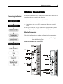
1
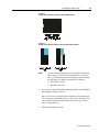
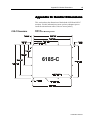
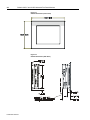
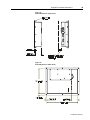
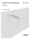
Industrial 15" and 12.1"
Flat Panel Monitors
Bulletin 6185-C and Bulletin 6185-B
Installation and User Manual
2
Bulletin 6185-C and 6185-B Industrial Flat Panel Monitors
6185-C and 6185-B Industrial Flat Panel Monitors ...........
Description ..............................................................................
Part Numbers...........................................................................
6185-C Monitor Hazardous Locations ....................................
Power Indicators......................................................................
Installing Your Monitor ........................................................
Before you Begin.....................................................................
Installing Your Monitor ...........................................................
Making Connections..............................................................
Connecting the Monitor...........................................................
Safety Considerations..............................................................
Connecting a Host Video Source.............................................
Connecting the Touchscreen Interface (Optional) ...................
Connecting Power ...................................................................
Configuring Video Setup.......................................................
Setting Up Your Workstation...................................................
Starting the Screen Setup Utility .............................................
Adjusting Your Monitor with the OSD....................................
Full Range Dimming Control (Optional 6185-C Only) .........
Calibrating the Video Gain ......................................................
Performing Routine Maintenance........................................
Cleaning...................................................................................
Replacing a Line Cord.............................................................
Other Maintenance ..................................................................
Troubleshooting and Support...............................................
Troubleshooting.......................................................................
Allen-Bradley Support ............................................................
Appendix A: Installing Your Monitor in a Rack................
Installing the 6185-C with Optional Rack Adapters................
Appendix B: Monitor Dimensions........................................
6185-C Dimensions.................................................................
6185-B Dimensions.................................................................
Appendix C: Touchscreen Serial Interface .........................
Description ..............................................................................
Setting Up the Touchscreen Interface......................................
Appendix D: Video Cables....................................................
HD-15 Video Connector..........................................................
Appendix E: Product Specifications ....................................
Publication 6185-5.1
5
6
8
9
9
10
10
12
15
15
16
16
17
17
20
21
24
25
31
33
34
34
34
34
35
35
37
38
38
41
41
44
46
46
46
49
49
50
3
Important User Information
Solid state equipment has operational characteristics differing from those of
electromechanical equipment. "Safety Guidelines for the Application, Installation, and Maintenance of Solid State Controls"
(Publication SGI-1.1) describes some important differences between solid state equipment and hard-wired electromechanical
devices. Because of this difference, and because of the wide variety of uses for solid state equipment, all persons responsible for
applying this equipment must satisfy themselves that each intended application of this equipment is acceptable.
In no event will Rockwell Automation be responsible or liable for indirect or consequential damages resulting from the use or
application of this equipment. The examples and diagrams in this manual are included solely for illustrative purposes. Because
of the many variables and requirements associated with any particular installation, Rockwell Automation cannot assume
responsibility or liability for actual use based on the examples and diagrams.
No patent liability is assumed by Rockwell Automation with respect to use of the information, circuits, equipment, or software
described in this manual.
Reproduction of the contents of this manual, in whole or in part, without written permission of Rockwell Automation is
prohibited.
Throughout this manual, we use notes to make you aware of safety considerations.
ATTENTION: Identifies information about practices or circumstances that can
lead to personal injury or death, property damage, or economic loss.
Important: Identifies information that is especially important for successful application and understanding of the product.
Publication 6185-5.1
4
Bulletin 6185-C and 6185-B Industrial Flat Panel Monitors
Publication 6185-5.1
6185-C and 6185-B Industrial
Flat Panel Monitors
This manual provides installation, operation, and maintenance
instructions for the Allen-Bradley 6185-C and 6185-B monitors.
This manual supports the following Rockwell Automation models:
• 15.0” Panel mount (6185-C)
• 12.1” Panel mount (6185-B)
Note:
If you want to place your monitor into a rack, you can use
the optional rack adapters brackets.
Figure 1
6185-C and 6185-B Panel Mount
Figure 2
6185-C Panel Mount
with Optional Rack Adapter Brackets
Publication 6185-5.1
6
Bulletin 6185-C and 6185-B Industrial Flat Panel Monitors
Description
The 6185-C and 6185-B monitors offer the following:
• 256K color (18-bit) display
• AC or DC power options
• Plug and Play compatible
• 120°H, 100°V viewing angle
Capabilities specific to the 6185-B include the following:
• Bright (250 nits) Active Matrix-TFT 800x600 display
• Video formats supported from 640x480 to 800x600
Capabilities specific to the 6185-C include the following:
• Bright (200 nits) Active Matrix-TFT 1024x768 display
• Video formats supported from 640x480 to 1024x768
• Class 1, Division 2 Hazardous Area Certification
ATTENTION: The equipment described in this
document generates, uses, and emits radio frequency
energy. The equipment has been tested and found to
comply with FCC Rules, Part 15, subpart J, for Class A
computing devices.
The use of non-shielded interface or power cords with
Allen-Bradley industrial monitors is prohibited.
Available Options
The following options are available:
• AC and DC power options
• NEMA 4/12 (IP65/IP53 equivalent) or 4X (stainless steel) front panel
options
• Touchscreen options
• Video cable options
• Power cord options
The following are also available for the 6185-C:
• Full-range dimming
• Rack mount adapter brackets (EIA-19 8U)
Publication 6185-5.1
6185-C and 6185-B Industrial Flat Panel Monitors
7
Package Contents
The shipping cartons contain the following items:
• Monitor
• Screen setup utility on floppy diskette
• Package of mounting hardware
• AC power cord (optional)
• Video cable (optional)
• This user manual
A monitor with a touchscreen option ships with these additional items:
• Supporting software and manuals
• RS-232 serial extension cable (optional)
Publication 6185-5.1
8
Bulletin 6185-C and 6185-B Industrial Flat Panel Monitors
Part Numbers
The part number for your particular unit consists of the Bulletin number
(6185) followed by a seven-digit code indicating the size (B or C) and
options on your unit.
Following are explanations of the part numbers for the various models of
monitors.
Example:
6185
C
A
A
A
A
A
Z
1
2
3
4
5
6
7
8
Table A
Catalog Number Explanation for 6185-C and 6185-B Monitors
Position
Option
2
Enclosure type
3
Front Panel
Type
4
Touchscreen/
Display Shield
5
6
7
8
Publication 6185-5.1
Power input
Category Description
Option
Letter
B
12.1” Panel Mount Monitor
C
15.0” Panel Mount Monitor
A
NEMA 4/12 Aluminum Panel
B
NEMA 4X Stainless Steel Panel
A
Resistive Polished Touchscreen
C
Resistive Antiglare Touchscreen
W
Tempered Glass Anti Reflective Display Shield
Z
Polycarbonate Polished Display Shield
A
120/240 AC input, USA Power Cord
B
120/240 AC input, No Power Cord
C
24V DC Input
External video
cable
A
6 foot (1.8 meter) HD15-HD15 Cable
B
15 foot (4.6 meter) HD15-HD15 Cable
Z
None
Touchscreen
serial cable
A
6 foot (1.8 meter) DE9-DE9 Cable
Accessories
B
15 foot (4.6 meter) DE9-DE9 Cable
D
6 foot (1.8 meter) DB9-DB25 Cable
Z
None
A
Full Range Dimming, 6185-C only
R
Rack Mount Adapter Brackets (EIA19-8U),
6185-C only
6185-C and 6185-B Industrial Flat Panel Monitors
6185-C Monitor
Hazardous Locations
9
See the nameplate label on the 6185-C monitor for certifications.
ATTENTION: In Class I, Division 2 hazardous
locations, the panel mount (6185-C) must be wired per
the National Electric Code and/or Canadian Electric code
as it applies to hazardous locations.
Power Indicators
A bi-color LED is provided on the front panel to indicate various
operating modes. The following table describes the functions assigned to
each color.
Table B
Power Indicator LED
LED Color
Indication
Green (solid)
Power ON, video sync detected (normal operation)
Amber (solid)
Power ON, loss of video sync or disconnected video
cable
Optional Full Range Dimming is available on 6185-C models. If your
monitor has this option, you will have two LEDs. For more details on
using the Full Range Dimming functionality and reading the LEDs, see
Adjusting the Full Range Dimming Control on page 30.
Publication 6185-5.1
10
Bulletin 6185-C and 6185-B Industrial Flat Panel Monitors
Installing Your Monitor
Before you Begin
This section describes how to install the 6185-C and 6185-B.
When installing the monitor, it is important to consider environmental
factors that could affect performance as well as possible effects from
equipment operation on personnel and nearby equipment.
The figure on the left displays the general process to install, connect, and
adjust your monitor.
Installation Guidelines
Following these guidelines will help ensure that the monitor provides
safe and reliable service.
• Ensure that sufficient power is available from a single phase AC
outlet at the site.
• Ensure that sufficient space is available around air inlets and outlets
to provide the circulation necessary for cooling. Never allow air
passages to become obstructed.
• Ensure that the ambient air temperature will not exceed the
specified maximum temperature. You may need a user-supplied fan,
heat exchanger, or air conditioner to meet this condition in some
installations.
Note:
Remember that heat rises—many times the temperature at
the top of an enclosure is much higher than the rest of the
enclosure if the air is not circulating.
Important: This monitor is designed to operate at a range of extremes,
however it is not good design practice to continuously
operate the monitor at the highest end of the specified
temperature range.
While the product will operate at its highest specified
temperature, the overall life span of any electronic device is
shortened when it operates at its highest rated temperature.
• Leave the monitor’s enclosure or cover in place at all times during
operation. The cover affords protection against high voltages inside
the monitor and inhibits radio-frequency emissions that might
interfere with other equipment.
• The Federal Communications Commission has prepared a pamphlet
that addresses the problem of radio frequency interference to radio
Publication 6185-5.1
Installing Your Monitor
11
and television reception, which should be consulted in case of
problems with such interference. This publication, “How to Identify
and Resolve Radio/TV Interference Problems” (Stock #004-00000345-4) may be obtained from the US Government Printing Office,
Washington, DC 20402.
• Determine the minimum and maximum ambient humidity for the
monitor by consulting the Appendix E: Product Specifications on
page 50. Ensure that the humidity of the ambient air will not exceed
these limits. In very dry environments, static charges build up very
readily. Proper grounding of the equipment through the AC power
cord can help reduce the likelihood of static discharges, which may
cause shocks and damage electronic components.
Publication 6185-5.1
12
Bulletin 6185-C and 6185-B Industrial Flat Panel Monitors
Installing Your Monitor
Panel mount monitors are designed to provide protection against water
and dust to NEMA 4 (IP65) and NEMA 12 (IP53) standards.
Slides or shelves are not required because the panel mount monitor is
designed to be supported by the panel in which it is installed.
Note:
Using optional rack adapters, you can install the 6185-C
into a rack. For procedures, skip this section and see
Appendix A: Installing Your Monitor in a Rack on page 38.
Figure 3
Generic Panel Mount Diagram
Tools Needed
In addition to the tools required to make the panel cutout, you will need
the following tools:
• 3/8" deep well socket
• ¼" drive extension – 6" or longer
• ¼" drive ratchet or ¼" drive torque ratchet
Publication 6185-5.1
Installing Your Monitor
13
Panel Mounting Guidelines
Observe the following precautions before installing the unit in a panel:
• Confirm that there is adequate space behind the panel. Remember to
allow extra space (0.5 in. or 12.7 mm behind and on each side) for air
circulation.
− For a 6185-C, a cabinet with a minimum depth of 4.4 in. (112mm)
is sufficient.
− For a 6185-B, a cabinet with a minimum depth of 3.25 in.
(82.6mm) is sufficient.
• Take precautions so that metal cuttings do not enter any components
that are already installed in the panel.
• Supporting panels should be at least 14 gauge to ensure proper
sealing against water and dust and to provide proper support. The
mounting hardware supplied accommodates panels up to 0.25 in.
(6.35 mm) thick.
Note:
Supporting panels must be cut and drilled to
specifications before installation.
ATTENTION: Failure to follow these warnings may
result in personal injury or damage to the panel
components.
Before Unpacking the Monitor
Before unpacking a new monitor, inspect the shipping carton for
damage. If damage is visible, immediately contact the shipper and
request assistance. Otherwise, proceed with unpacking.
Note:
Make sure you keep the original packaging for the monitor
in case you need to return the monitor for repair.
Installing Your Monitor
1. Prepare panel cutout for monitor. Refer to specific cutout drawings
in Appendix B: Monitor Dimensions on page 41.
2. Carefully remove the monitor from its packaging.
Publication 6185-5.1
14
Bulletin 6185-C and 6185-B Industrial Flat Panel Monitors
3. If access to the side of the monitor is not available following
installation, attach the power and video cables to the side of the
monitor at this time. Refer to the figure on Page 15.
4. Install the monitor in the prepared cutout.
5. Install the lock nuts and washers, supplied with the monitor, around
the perimeter of the monitor. Extra lock nuts and washers are
provided.
Note:
Use #10-32 or M5 self-locking nuts for mounting.
ATTENTION: You must apply nuts and washers on all
studs for NEMA 4/12 fluid applications.
6. Tighten all mounting nuts evenly to a torque of 24 inch-pounds.
ATTENTION: Mounting nuts must be tightened to a
torque of 24 inch-pounds to provide panel seal and avoid
potential damage. Rockwell Automation assumes no
responsibility for water or chemical damage to the
monitor or other equipment within the enclosure due to
improper installation.
Publication 6185-5.1
Making Connections
15
Making Connections
Connecting the Monitor
Side panels of both the 6185-C and 6185-B monitors have connectors for
attaching cables to accomplish the following:
• Connecting to a host video source (HD-15 VGA connector)
• Connecting to a host touchscreen
• Connecting to AC power (IEC connector) or DC power (terminal
block)
In the figure on the left, the gray shaded areas represent where you are
now in the general process to install, connect, and adjust your monitor.
Monitor Connections
The following figure shows standard configurations for your monitor.
Note:
Some connectors on your monitor may differ slightly
from the following figure.
Figure 4
6185-C and 6185-B Monitor Connections
Publication 6185-5.1
16
Bulletin 6185-C and 6185-B Industrial Flat Panel Monitors
Safety Considerations
When connecting the monitor, note the following safety considerations:
ATTENTION: EXPLOSION HAZARD! – Substitution
of components (6185-C) may impair suitability for Class
I, Div. 2.
EXPLOSION HAZARD! – Do not disconnect
equipment (6185-C) unless power has been switched off
or the area is known to be non-hazardous.
Connecting a Host Video
Source
The video connection to the host is made through a HD-15 (female)
connector located on the side panel.
Note:
For more information on using a HD-15 video cable to
connect to the host computer, see page 49.
To establish a signal using the HD-15 connector:
1. Obtain a shielded, properly terminated video cable of length as short
as possible. Longer cables (up to approximately 75 feet in some
cases) may be used, provided they are properly constructed. Your
package may include a six-foot or 15-foot video cable, if specified.
2. Connect one end of the cable to the female HD-15 video input
connector on the side panel of the monitor.
3. Connect the other end to the output of any IBM-compatible VGA
adapter or other video generator.
Note:
Publication 6185-5.1
You may connect the monitor to video generators that
do not conform to VGA standards. The main
requirement is that the generator provides analog RGB
video signals (0.714V above reference black into 75
ohms) and separate horizontal and vertical sync signals.
Making Connections
Connecting the
Touchscreen Interface
(Optional)
17
The serial touchscreen interface connection to the host is made through
an RS-232 DE-9 (female) D-shell connector located on the side panel.
The optional touchscreen provides a high-resolution touch input system.
Driver software included with the package allows the touchscreen to
function with many popular DOS and Windows® -based industrial
applications as a pointing device (mouse).
Note:
Refer to Appendix C: Touchscreen Serial Interface on page
46 for additional details on the installation and operation of
the touchscreen.
To connect the touchscreen:
1. For units with the touchscreen option, make sure you have one of the
optional serial cables.
2. Connect one end of the touchscreen serial cable to the T/S port
connector on the side of the monitor.
3. Connect the other end to any communications port on the host
computer.
4. Tighten the captive screws on the cable connector to secure it.
Connecting Power
Allen-Bradley monitors can be ordered with either AC or DC power
option.
Connecting AC Power
The 6185-C and 6185-B monitors with an AC power option require a
single-phase power supply providing 85 to 264V AC at 47 to 70 Hz.
Power must be available at a grounded three-pin outlet located nearby.
Whenever possible, connect the monitor to the same AC source that
supplies the computer.
To connect AC power to the monitor:
1. Turn off the main switch or breaker.
2. Use the ground terminal of the monitor to establish a chassis-to-earth
ground connection. The ground terminal is an M5 screw. Secure one
end of a ground strap to the ground terminal. Connect the other end
of the ground strap to a good earth ground.
Publication 6185-5.1
18
Bulletin 6185-C and 6185-B Industrial Flat Panel Monitors
ATTENTION: Chassis ground must be connected for
safe operation of the monitor. The AC receptacle on the
monitor is a 3-wire type with chassis ground pin, and the
mating AC cord supplied is a 3-wire type, designed for
connection to a grounded 3-pin AC outlet. However, a
properly ground AC outlet is not always available, and
grounding using a 3-wire cord can easily be defeated. If
you fail to ground the monitor properly, the setup may
result in personal injury from electrical shock or damage
to the equipment.
3. Connect the socket end of the AC power cord to the mating
connector on the side of the monitor and secure the cord with the
power cord retainer clip. See the figure on page 15.
ATTENTION: EXPLOSION HAZARD! You must
install the power cord retainer clip to ensure safety in
hazardous locations.
Failure to secure the power cord with the retainer clip
could result in hazardous conditions if the power cord is
accidentally disconnected.
ATTENTION: EXPLOSION HAZARD! – Do not
disconnect equipment unless power has been switched off
or the area is known to be non-hazardous.
4. Connect the plug end of the AC power cord to the main outlet.
5. Restore AC power to the outlet.
6. Proceed to Configuring Video Setup on page 20.
Connecting DC Power
The 6185-C and 6185-B monitors with a DC power option require a DC
power supply providing 18 to 32V DC.
To connect DC power to the monitor:
1. Turn off the main switch or breaker.
2. Use the ground terminal on the monitor to establish a chassis-toearth ground connection. The ground terminal is an M5 screw.
Secure one end of a ground strap to the ground terminal. Connect the
other end of the ground strap to a good earth ground.
Publication 6185-5.1
Making Connections
19
ATTENTION: Chassis ground must be connected for
safe operation of the monitor. The DC screw terminals on
the monitor have a chassis ground pin. However, some
DC sources may not provide a proper ground path. If you
fail to ground the monitor properly, the setup may result
in personal injury from electrical shock or damage to the
equipment.
ATTENTION: EXPLOSION HAZARD! – Do not
disconnect equipment unless power has been switched off
or the area is known to be non-hazardous.
3. Route the power wires from your 18-32 VDC power supply and
connect the leads to the DC input terminal block on the monitor as
shown in the following figure. Tighten the screw terminals to ensure
a good connection.
Note:
Be sure to follow the labeling on the DC power supply
terminal block to prevent damage to your monitor.
Figure 5
Connecting Power to the Terminal Block
4. Restore DC power.
Publication 6185-5.1
20
Bulletin 6185-C and 6185-B Industrial Flat Panel Monitors
Configuring Video Setup
After making the connections, you are ready to setup your monitor.
This section describes how to setup and configure your monitor.
You will need to use the following procedures:
• Setting Up Your Workstation - verifies that your workstation is using
the appropriate settings. See page 21.
• Using the Screen Setup Utility - provides graphical guidelines to use
when adjusting the OSD settings. See page 24.
• Working with the OSD - allows you to physically change the monitor
settings on the monitor. See page 25.
In the figure on the left, the gray shaded areas represent where you are
now in the general process to install, connect, and adjust your monitor.
Importance of Correctly Setting Up the Monitor
If you do not correctly set up the flat panel monitor, the image may
appear correct when you view the Windows Desktop (the screen
displayed initially displayed when Windows starts). However, when you
display an application with certain colors or patterns, you may notice
noisy video or jitter problems at that time.
For example, if the horizontal or vertical position of the display is not
adjusted correctly, one edge of the screen image may extend beyond the
side of the monitor screen.
The horizontal size and clock phase adjustments are especially important
for flat panel monitors. If the horizontal size setting is not properly
adjusted, the screen image may contain vertical shaded bars or the image
may be too wide or too narrow for the screen. If the clock phase setting
is not properly adjusted, the screen image may be “jittery.”
Publication 6185-5.1
Configuring Video Setup
21
Figure 6
Monitor Video Adjustments
You may also need to adjust the brightness or contrast of the screen
image based on the conditions of the location in which the monitor is
installed.
Setting Up Your
Workstation
Note:
The screen setup utility delivered with this flat panel
monitor is designed to present the "worst case" scenario for
graphic display. It shows a range of colors and presents a
pattern you can use to ensure that the monitor is adjusted
properly.
Note:
Flat panel monitors are not susceptible to magnetic
interference in the same way that CRT monitors are.
However, all monitors are susceptible to ground loop
problems between the computer and the monitor. Ground
loops occur when two or more devices with different
ground potentials are connected with cables and ground
currents flow between. These currents may cause vertical or
horizontal noise bars to move through the display screen.
Verify and change these settings for your workstation using the Windows
Control Panel.
To access monitor settings, select the Start button and select Settings to
access Control Panel. In Control Panel, select Display to access monitor
settings. The options on the Control Panel screens may vary depending
on your video driver.
Selecting the Monitor Type
If you are using Windows 95, Windows 98 or Windows 2000 and your
video card supports it, you should enable your workstation to detect Plug
& Play monitors and select Plug and Play as the monitor type.
Publication 6185-5.1
22
Bulletin 6185-C and 6185-B Industrial Flat Panel Monitors
Note:
These monitors use a flat panel display, but they use the
workstation’s analog VGA interface. Because of this, some
setup screens may indicate that the monitor is operating as a
CRT (analog) device, rather than a flat panel (digital)
device.
If your video card does not support Plug and Play, or if you are using
Windows NT, you should the monitor type manually. These settings are:
• Plug and Play Monitor - 6185-C and 6185-B with Plug and Play
enabled system
• Super VGA 1024x768 - 6185-C manual setting
• Super VGA 800x600 - 6185-B manual setting
Depending on if you are using Windows NT, Windows 95 or Windows
98, accessing the settings differ.
Use the following table as a procedure guideline for accessing the
monitor types manually.
Table C
Procedures for Accessing Monitor Type Manually
Windows NT
Publication 6185-5.1
Windows 95
Windows 98
1.
Open Control Panel
1.
Open Control Panel
1.
Open Control Panel
2.
Open Display icon
2.
Open Display icon
2.
Open Display icon
3.
Click Settings tab
3.
Click Settings tab
3.
Click Settings tab
4.
Verify Desktop Area
(Resolution)
4.
Click Advance
Properties button
4.
Click Advance
Properties button
5.
Verify Refresh
Frequency
5.
Click Monitor tab
5.
Click Monitor tab
6.
Click Change button
6.
Click Show all
Devices button
7.
Click Show all
Devices button
7.
Verify Manufacturer:
Standard monitor
types
8.
Verify Manufacturer:
Standard monitor
types
8.
Verify Models:
•
Plug and Play
Monitor
9.
Verify Models:
•
•
Super VGA 800x600
Plug and Play
Monitor
•
•
Super VGA
1024x768
Super VGA 800x600
•
Super VGA
1024x768
23
Configuring Video Setup
Setting Up Video Resolution
Flat panel monitors are fixed resolution devices and the image looks best
when operated at their native resolution.
If you switch the resolution of this monitor from the native resolutions,
the display may look slightly distorted due to replication techniques used
to display the full screen. The native resolutions are as follows:
• 1024x768 for 6185-C
• 800x600 for 6185-B
The following table lists the amount of video memory you need to run in
each video mode:
Table D
Video Memory Requirements
Resolution
640x480
800x600
1024x768
Note:
Color Mode
Video Memory
256 colors (8 bit)
0.4 Mb
High color (16 bit color)
0.7 Mb
True Color (24 bit color)
1.0 Mb
256 colors (8 bit)
0.6 Mb
High color (16 bit color)
1.0 Mb
True Color (24 bit color)
1.5 Mb
256 colors (8 bit)
0.9 Mb
High color (16 bit color)
1.7 Mb
True Color (24 bit color)
2.4 Mb
The 6185-C and 6185-B monitors display up to 256k colors
(18-bit color). Because most workstations only support
8-bit, 16-bit, or 24-bit color, you must operate the monitor
in True Color mode (24-bit color) to use the full color range
of the monitor. The monitor will interpret the colors
correctly.
Verifying Video Refresh Rate
Unlike CRT monitors, there is no benefit to operating a flat panel
monitor at higher vertical refresh rates. It is best to select 60 Hz.
You can verify video refresh rate for your workstation using the
Windows Control Panel.
Publication 6185-5.1
24
Bulletin 6185-C and 6185-B Industrial Flat Panel Monitors
Starting the Screen Setup
Utility
1. Insert the diskette provided with the monitor in the floppy drive of
the host computer.
Note:
This utility is designed for 32-bit operating systems
only (Windows 95/98/2000 or Windows NT 4.0 or
greater).
2. Start the screen setup utility using the instructions on the diskette
label.
The following is an example of the screen setup utility.
Publication 6185-5.1
Configuring Video Setup
Adjusting Your Monitor
with the OSD
25
Your monitor is equipped with three controls or pushbuttons on the rear
panel:
• Select
• Up
• Down.
These controls allow you to operate the OSD to adjust and setup your
monitor.
Figure 7
Controls on Back Panel
The following table provides a summary to using the pushbuttons:
Table E
Pushbutton Guidelines
The Select Pushbutton…
The Up and Down Pushbuttons…
Starts the OSD.
Highlight the option you want.
Selects a highlighted option.
Adjust the selected option higher or
lower.
Saves the value and returns to the
previous menu.
Publication 6185-5.1
26
Bulletin 6185-C and 6185-B Industrial Flat Panel Monitors
Working with the OSD
Starting the OSD
1. Press the Select pushbutton to display the OSD.
Verifying Workstation Settings
You changed the settings in Setting Up Your Workstation on page 21.
This procedure verifies your selections.
1. Highlight the System Menu option using the up and down
pushbuttons and press Select.
2. Verify that you are using the desired settings:
•
Resolution of 1024x768 for 6185-C or 800x600 for 6185-B
works best
•
Vertical refresh rate of 60 or 75Hz.
3. If necessary, change the resolution or video refresh rate for the
workstation using the Windows Control Panel.
Using the Auto-Adjust Feature
Using the auto-adjust feature automatically adjusts the monitor correctly,
often requiring no additional changes.
1. Highlight the Auto Adjust option and press Select.
The monitor attempts to adjust the settings properly based on the
current signal. This process may take up to 20 seconds.
Verifying the Horizontal Size
Verify that the horizontal size is adjusted correctly. You should see
individual lines through the center section of the setup image. See the
figures in this section for detail:
Changing the horizontal size setting adjusts the width of the image on the
monitor from left to right; thus adjusting the sample rate of the monitor
to match the pixel clock rate of the workstation's video card.
1. Highlight the Position option and press Select.
2. Highlight the Horizontal Size option and press Select.
3. Adjust the horizontal size until the vertical shaded bars disappear.
Publication 6185-5.1
Configuring Video Setup
27
Figure 8
Setup Screen Example, Needing Video Adjustments
Figure 9
Setup Screen Example Detail: Horizontal Size Adjustment
Note:
If you are running the monitor with a resolution other than
native mode, you will not see individual lines in all cases.
This is a result of the replication techniques used to display
the full image. The native resolutions are as follows:
• 1024x768 for 6185-C
• 800x600 for 6185-B
4. Once you have adjusted the horizontal size until the vertical shaded
bars disappear, then press Select.
Since you have not yet adjusted the clock phase of the monitor, the
lines may appear consistently fuzzy or jittery across the image. You
may need to complete the adjustment process before the vertical
lines are sharp and crisp.
5. Exit the Horizontal Size menu.
Publication 6185-5.1
28
Bulletin 6185-C and 6185-B Industrial Flat Panel Monitors
Verifying the Horizontal Position
Verify that the horizontal position is set correctly. The setup image has a
thin white border around the image. It should be visible on the right and
left sides of the screen.
1. Highlight the Horizontal Position option and press Select.
2. Adjust the horizontal screen position so that the white border line is
visible on both sides of the image.
If the horizontal size and position are adjusted correctly, you should
be able to adjust the horizontal position one adjustment to the left or
right and the white border line should move off the edge of the
screen. If this does not occur, you may need to repeat the horizontal
size adjustment step.
3. Exit the Horizontal Position menu.
Verifying the Vertical Position
Verify that the vertical position is set correctly. The setup image has a
thin white border around the image. It should be visible on the top and
bottom sides of the screen.
1. Highlight the Vertical Position option and press Select.
2. Adjust the vertical screen position so that the white border line is
visible on the top and bottom of the image.
3. Exit the Vertical Position menu.
Verifying the Clock Phase
Verify that the clock phase of the monitor is adjusted to best match the
input video signal. An incorrect phase adjustment will show up on screen
as “jitter” or fuzzy lines through the center section of the setup image.
1. Highlight the Clock Phase option and press Select.
2. Adjust the clock phase until the screen image is sharp and there is no
screen “jitter.”
This adjustment selects the best match the video clock rate of the
workstation’s video card
3. Exit the Clock Phase menu.
Publication 6185-5.1
Configuring Video Setup
29
Adjusting the Brightness
Changing the brightness setting adjusts the overall intensity of the
monitor. To obtain the best display, first set the brightness control to the
appropriate setting under the lighting conditions in which the monitor
will be used.
Note:
Allow time for the backlight on the monitor to warm up
completely before you adjust the brightness control.
1. Highlight the Brightness option and press Select.
2. Adjust the brightness value to its lowest setting.
3. Adjust the brightness until the black bar at the top of the screen
changes from black to dark gray.
4. Adjust the brightness down until the bar changes back to black. This
is the optimal brightness setting given the current lighting
conditions.
5. Exit the Brightness menu.
Adjusting the Contrast
Changing the contrast setting adjusts the difference between the
monitor's light and dark elements. The optimum setting may vary
slightly with different types of monitors and changes in ambient lighting,
as well as individual taste.
1. Highlight the Contrast option and press Select.
2. Adjust the contrast value up to its highest setting. The gray bars on
the bottom of the screen image change to white.
Adjust the contrast down until the white bar stays white and the first
light gray bar changes back to light gray. The figure below is the
optimal contrast setting given the current lighting conditions.
Figure 10
Contrast Adjustment
3. Exit the Contrast menu.
Publication 6185-5.1
30
Bulletin 6185-C and 6185-B Industrial Flat Panel Monitors
OSD Menu Reference
You can make other adjustments in addition to the most common ones
previously listed. Use the following table as a reference of the available
options on the OSD menu.
OSD Menu Items
Basic Adjustment Menu
Image Position Menu
System Menu
Auto-Adjustment Menu
Description
Brightness
Adjusts the overall intensity of the monitor.
Contrast
Adjusts the difference between the monitor's light and dark
elements.
Color Balance
Adjusts the balance of red, green, and blue colors used in the
display. This will change the overall color temperature of the
monitor.
Clock Phase
Adjusts the clock phase of the monitor to best match the video
clock rate of the workstation’s video card.
Default Settings
Returns to the default values. These default values may not be
the same as the ones that were set when you received your
monitor. Allen-Bradley often changes the defaults by lowering the
brightness and increasing the contrast. Also, the phasing will be
different depending on the specific configuration for your monitor.
Horizontal Position
Adjusts the location of the image on the monitor from left to right.
Horizontal Size
Changes the width of the image on the monitor from left to right.
Adjusts the sample rate of the monitor to match the pixel dock
rate of the workstation's video card. The vertical size is set
automatically by the monitor according to the video signal.
Vertical Position
Adjusts the location of the image on the monitor from top to
bottom.
Language
Changes the screen setup utility language. Options are English,
French, Italian, German, and Spanish.
OSD Position
Changes the location of the screen setup utility with the user
interface settings.
OSD Turn Off Time
Changes the timeout period for the screen setup utility (how long
before it will automatically disappear if not used).
Current Video
Signal
Changes the monitor functions based on the current video signal.
Automatically sets up the monitor based on the current video
signal.
Auto Adjust works best on a full screen of data. Results may not
be accurate if image does not go to the edges of the screen. The
Screen Setup utility is an ideal image for Auto Adjustment.
Exit Menu
Publication 6185-5.1
Closes the screen setup utility.
Configuring Video Setup
Full Range Dimming
Control
(Optional 6185-C Only)
31
Allen-Bradley provides a full range dimming control option for the
6185-C that allows full range control of image luminance from the front
panel. The full range dimming control option is Accessory option A.
Adjusting the Full Range Dimming Control
The LEDs are present with or without the dimmer control, but the two
buttons that adjust the luminance of the monitor are optional.
Figure 11
Optional Full Range Dimming Control
Note:
The dimming controls are located on the rear of the monitor
with the optional stainless steel front panel.
The control buttons adjust the luminance of the image, which is not the
same as a brightness setting. Luminance refers to the actual intensity of
the light emitted from the monitor. Brightness refers to the appearance of
the image displayed – a range between dark and dazzling. The backlights
are controlled by the luminance control.
Publication 6185-5.1
32
Bulletin 6185-C and 6185-B Industrial Flat Panel Monitors
To adjust the luminance of the monitor:
Press and hold either one of the dimmer buttons until the luminance is
adjusted as desired.
• The left dimmer button reduces the luminance and the right button
increases it.
• The green LED blinks fast when you first press the button and slows
as you reach the end of the adjustment range.
• When you release the dimmer button for three seconds, the amber
LED blinks twice to indicate that your changes have been saved and
will be used each time the monitor is powered ON.
To turn off the monitor without turning off the power:
1. Press and hold both buttons for 2 seconds, until the monitor’s
backlight is turned OFF.
2. Press either button to turn the backlight back ON.
Table F
Interpreting the Dimmer LED
Green LED
Amber LED
Condition
On
Off
Normal Operation - The monitor is receiving a valid video
signal.
Off
On
Signal Not Received - The monitor is not receiving a valid
video signal.
On (blinking
slowly)
Off
Backlight Off - The monitor is still ON but the backlight is
powered OFF. Hold down both buttons for 2 seconds to
disable the backlight. Press either button to enable the
backlight.
On (blinking fast
then slow)
Off
Changing Dimmer Setting - When you are pressing one
of the dimmer buttons, the LED blinks fast and slows
down as you reach the end of the possible dimmer
adjustments in that direction. The light stops blinking
when you stop pressing the button, and the amber LED
blinks twice when the change has been saved. Once a
dimmer setting has been saved, it will be used each time
the display is powered ON.
Off
On (blinking
slowly)
Calibration Mode - See instructions below.
Publication 6185-5.1
Configuring Video Setup
Calibrating the Video Gain
33
Monitors with this a full range dimming control option have a calibration
mode to allow you to compensate for abnormal video signal levels.
Many PC video cards drive the video signal above the .714V as defined
by the VGA standard. You may need to calibrate the video gain if you
see “ghosting” (shadows to the right of the image) or washed out colors.
To calibrate the monitor:
1. Insert the diskette provided with the monitor in the floppy drive of
the host computer.
Note:
The adjustment utility is designed for 32-bit operating
systems only (Windows 95/98/2000 or
Windows NT 4.0 or greater).
2. Start the screen setup utility using the instructions on the diskette
label.
3. Press and hold down both luminance buttons for eight seconds.
Note:
The screen will go blank after two seconds and will
come back on after eight seconds.
The amber LED blinks slowly to indicate that you are in calibration
mode.
4. Use the left luminance button to lower the contrast until the white
bar stays white and the first light gray bar changes back to light gray.
This is the optimal setting for the video gain. (See the figure on
Page 29.)
5. Press and hold down both luminance buttons for two seconds to exit
calibration mode.
The amber light blinks twice when the calibration is complete.
Publication 6185-5.1
34
Bulletin 6185-C and 6185-B Industrial Flat Panel Monitors
Performing Routine Maintenance
Cleaning
Occasionally clean the display panel and cabinet with a soft cloth
dampened (not soaked) with a mild (non-abrasive) glass cleaner. Keep
turning a fresh side of the cloth toward the screen surface to avoid
scratching it with accumulated grit.
Note:
The solvent should be applied only to the cloth, and not
directly on the monitor screen.
Do not use paper products as they may scratch the surface.
To minimize the risk of abrasion, allow the screen to
stand dry.
Special care should be taken when cleaning a touchscreen or
polycarbonate shield that is installed over the screen. Abrasive and
certain chemical cleaners can easily damage the surface.
Note:
Replacing a Line Cord
For best results cleaning a monitor with the optional,
antireflective tempered glass display shield, a solution of
denatured alcohol is recommended to thoroughly clean the
display. Never use alcoholic or ammoniac cleaners to clean
the polycarbonate shield or a touchscreen.
To avoid shock and fire hazards, the monitor’s power cord should be
replaced if the insulation becomes broken or if it develops a loose
internal connection.
ATTENTION: EXPLOSION HAZARD! – Substitution
of components (6185-C) may impair suitability for Class
I, Div. 2 hazardous locations.
Other Maintenance
Publication 6185-5.1
Qualified service personnel should perform all maintenance, except for
the power cord replacement described above.
Troubleshooting and Support
35
Troubleshooting and Support
Troubleshooting
You can refer to this table to help identify the cause and offer a solution
to a problem. This table lists typical problems you may encounter.
Table G
Troubleshooting Table
Symptom
Front panel status LED does not come on.
Screen is blank.
Possible Problem
Action
Power cord not connected.
Connect the power cord.
No power available at outlet.
Test outlet by plugging in a lamp or other
known good device.
Power cord faulty.
Replace power cord.
Monitor faulty.
Have monitor serviced.
Screen saver activated.
Check the status LED using the table
provided on page 9. Disable screen saver
by activating an input to the host system.
Contrast or luminance control not properly
adjusted. (Luminance control on 6185-C
only.)
Turn brightness or luminance control UP.
Video cable problem.
Check for proper installation of video
cable(s). Refer to installation instructions.
Replace suspected faulty cable(s).
Image is too bright or white.
Contrast or luminance control not properly
adjusted.
Turn brightness or luminance control
DOWN.
No image visible even when brightness
control is set full UP.
Monitor is out of adjustment or faulty.
Have monitor serviced.
Image is dim, even with brightness and
contrast controls set full UP.
Video cable problem.
Check for proper installation of video
cable(s). Refer to installation instructions.
Fault in video source.
Test video source by connecting to
another monitor that is known to be
operational.
Fault in monitor.
Have monitor serviced.
Video timing outside of range.
Use the OSD to adjust the Clock Setting
(Page 28). Make sure timing is within
VESA.
Not operating in native resolution.
When not in native mode black bands
appear at the top and bottom of the
screen. The native resolutions are as
follows:
Replace suspected faulty cable(s).
Image will not adjust.
Image position changes are not saved.
Position mode not saved correctly.
•
1024x768 for 6185-C
•
800x600 for 6185-B
Reposition the image using the OSD. Wait
5 seconds for the changes to be saved
before you turn off power.
Publication 6185-5.1
36
Bulletin 6185-C and 6185-B Industrial Flat Panel Monitors
Symptom
Image is not stable.
Possible Problem
Monitor is not synched to video source.
Action
Refer to installation instructions.
Check for proper video cable installation.
Replace suspected faulty cable.
Check to ensure that video source is
operating within the display’s range. Adjust
the Clock Phase. See page 28.
Image not properly centered or sized.
Size and position controls incorrectly
adjusted.
Use autp-adjust feature for proper size and
position of image. See page 26.
Reset the horizontal and vertical
positioning using the OSD (Page 28).
Check to ensure that video source is
operating within the monitor’s range.
Vertical shaded bars on screen image.
Horizontal size not properly adjusted.
Adjust horizontal size settings. See page
26.
Color(s) are missing.
Video cable problem.
Check for proper video cable installation.
Replace suspected faulty cable.
Fault in monitor.
Have monitor serviced.
Monitor clock phase not properly
adjusted.
Adjust monitor clock phase settings See
page 28.
Video cable problem.
Check for proper video cable installation.
Replace suspected faulty cable.
Electrical noise interference from nearby
equipment.
Check for proper video cable routing and
installation. Reroute cables or replace
suspected faulty cables.
Screen jitter or noisy video.
Check host and monitor grounding.
Slight distortion in text or graphics.
Display is present, but “bars” appear
across it or roll through it.
Not operating monitor in native resolution.
“Noise” generated by other equipment in
the environment is present at the video
inputs.
Ground loop problems between computer
and monitor.
Image has blurry streaks or “ghosting” to
the right of objects on the screen.
Publication 6185-5.1
Change the video source to native mode.
The native resolutions are as follows:
•
1024x768 for 6185-C
•
800x600 for 6185-B
Consult the application note that
discusses methods of eliminating noise.
Eliminate ground loops by connecting
monitor and computer to the same power
source location or installing an AC
isolation transformer.
Contrast set too high.
Adjust contrast settings. See page 29.
Video cable problem.
Check for proper video cable installation.
Replace suspected faulty cable.
Troubleshooting and Support
Allen-Bradley Support
37
Allen-Bradley offers support services worldwide, with over 75
Sales/Support Offices, 512 authorized Distributors and 260 authorized
Systems Integrators located throughout the United States alone, plus
Allen-Bradley representatives in every major country in the world.
Local Product Support
Contact your local Allen-Bradley representative for:
• Sales and order support
• Product technical training
• Warranty support
• Support service agreements
Refer to the Rockwell Automation/Allen-Bradley Internet site at
http://www.ab.com for local contact information.
Technical Product Assistance
If you need to contact Allen-Bradley for technical assistance, please
review the information in the Troubleshooting section first. Then call
your local Allen-Bradley representative or contact Allen-Bradley
technical support at (440) 646-5800.
For additional product information and a description of the technical
services available, visit the Rockwell Automation/Allen-Bradley Internet
site listed above.
Publication 6185-5.1
38
Bulletin 6185-C and 6185-B Industrial Flat Panel Monitors
Appendix A: Installing Your
Monitor in a Rack
Installing the 6185-C with
Optional Rack Adapters
You can also install the 6185-C into a rack using optional rack adapters.
The rack adapters are designed for installation in a rack cabinet that
conforms to EIA standards for equipment with 19" (483 mm) wide
panels. The rack adapters option is Accessory option R.
Tools Needed
You will need the following tools:
• EIA panel mounting hardware
• Phillips screwdriver (medium)
6185-C Monitor Rack Mounting Guidelines
Observe the following precautions when installing this unit in a rack:
• The cabinet must be tall enough to accommodate the monitor's panel
height of eight rack units, 14.00" (400 mm), and deep enough to
accommodate the monitor's depth while providing rear clearance for
cabling and air flow. A cabinet with depth of 4.4" (112 mm) is
sufficient.
• No slides or shelves are required because the rack mount (6185-C)
monitor is designed to be supported by the panels in which it is
installed.
Publication 6185-5.1
Appendix A: Installing Your Monitor in a Rack
39
Installing Rack Adapter Brackets on a 6185-C Monitor
1. Carefully remove the monitor from its packaging.
2. Locate four mounting studs on each side of the monitor’s back
enclosure.
3. Install handles onto rack adapter brackets, if required.
4. Install the rack adapter brackets onto the four mounting studs on the
monitor’s back enclosure.
5. Secure the rack adapter brackets with the provided nuts for all eight
mounting studs (4 studs for each rack adapter bracket).
Publication 6185-5.1
40
Bulletin 6185-C and 6185-B Industrial Flat Panel Monitors
Installing a 6185-C Monitor into a Rack
1. Verify that you have eight rack units (14.0”) available to mount your
monitor.
2. Locate holes in the rack mounting rails corresponding to the holes in
the monitor front panel. Install clip nuts behind the holes in the rails
if threaded rails are not provided.
Note:
The mounting rails that run vertically along the inside
edges of the front opening of an EIA rack cabinet can
be of two types:
• “Wide” rails have holes spaced 0.5"(12.7 mm) and
1.25"(31.8 mm) on centers, in a repeating pattern.
Wide rails are prevalent in Europe.
• “Universal” rails have holes spaced 0.5"(12.7 mm),
0.625"(31.8 mm), and 0.625"(31.8 mm) on centers,
in a repeating pattern. Thus, the universal rails have
a hole pattern that contains the wide pattern but
provides an additional hole at the midpoint of the
pattern. Universal rails are most prevalent in the US.
3. Install the monitor into the cabinet from the front.
4. Secure the monitor chassis to the cabinet by installing panelmounting screws through the holes in the monitor’s front panel and
into the rails behind.
Publication 6185-5.1
Appendix B: Monitor Dimensions
41
Appendix B: Monitor Dimensions
This section shows the dimensions of the both the 6185-B and 6185-C
monitors. Use this information to ensure you have adequate space to
install the unit and route cables. Units are in mm [inches].
6185-C Dimensions
Figure 12
6185-C Panel Mounting Cutout
6185-C
Publication 6185-5.1
42
Bulletin 6185-C and 6185-B Industrial Flat Panel Monitors
Figure 13
6185-C Dimensions (Front View)
Figure 14
6185-C Dimensions (Side View)
Publication 6185-5.1
Appendix B: Monitor Dimensions
43
Figure 15
6185-C Dimensions (Back View)
Publication 6185-5.1
44
Bulletin 6185-C and 6185-B Industrial Flat Panel Monitors
6185-B Dimensions
Figure 16
6185-B Panel Mounting Cutout
6185-B
Figure 17
6185-B Dimensions (Front View)
Publication 6185-5.1
Appendix B: Monitor Dimensions
45
Figure 18
6185-B Dimensions (Side Views)
Figure 19
6185-B Dimensions (Back View)
Publication 6185-5.1
46
Bulletin 6185-C and 6185-B Industrial Flat Panel Monitors
Appendix C: Touchscreen Serial
Interface
Description
All touch controllers are configured by default to provide serial
communications at 9600 baud, 8 data bits, 1 stop bit, no parity.
For Allen-Bradley monitors equipped with touchscreens, a serial
communications cable is required. A suitable cable can be obtained from
Rockwell Automation or you can create one. The cable is a straightwired serial (RS-232) cable with a male DE-9 D-shell connector on the
monitor end.
The cable provides a communications channel between the touchscreen
controller, which is mounted inside the monitor, and an RS-232-C serial
port on the host computer. Because the touch controller obtains power
from the monitor's power supply, no external touch power connections
are necessary.
Software supplied with the touchscreen must be loaded on the host
computer to handle communications with the touch controller over the
channel.
Because the touchscreen emulates a mouse, there may be compatibility
issues involving how the touchscreen emulates mouse buttons, especially
multiple buttons. For a complete discussion of these issues and how to
troubleshoot them, refer to the touchscreen documentation.
Setting Up the
Touchscreen Interface
This section describes how to set up the touchscreen system. Setup
involves the following:
• Enabling the touchscreen interface
• Installing the software on the host computer that will handle
communications with the touchscreen controller
• Performing a calibration
Publication 6185-5.1
47
Appendix C: Touchscreen Serial Interface
Enabling the Touchscreen Interface
The 6185-C and 6185-B monitors provide a female DE-9 connector on
the side panel. This connector provides the serial interface for the touch
controller.
Interconnecting wiring to the host serial port connection is shown in the
following table.
Table H
Touchscreen Interface
Monitor
(DCE Device)
DE-9 (Female)
Signal Description
Host (DTE Device)
DE-9 (Male)
DB-25 (Male)
1
Not Connected (DCD)
1
8
2
Transmit Data (TXD)
2
3
3
Receive Data (RXD)
3
2
4
Data Terminal Ready (DTR)
4
20
5
Common Signal Return (SG)
5
7
6
Not Connected (DSR)
6
6
7
Request To Send (RTS)
7
4
8
Clear To Send (CTS)
8
5
9
Not Connected
9
22
Installing the Touchscreen Driver Software
To install the touchscreen driver software correctly, obtain the following
information about the host hardware:
• The COM port in use for the touchscreen. Ensure that the RS-232
cable is properly installed between the monitor port and the host’s
COM port.
• The baud rate at which the controller is operating. You will need to
match the baud rate at the COM port. The controller baud rate is
factory set at 9600.
Note:
If you are using older touchscreen software, you may be
prompted for the type of touchscreen controller being used.
The 6185-C and 6185-B monitors use the following
controllers:
• Resistive: Elo TouchSystems model E271-2210.
• Capacitive: MicroTouch model SMT-3.
Once you have obtained this information, install the software using the
installation disks found in the touchscreen accessory package.
Publication 6185-5.1
48
Bulletin 6185-C and 6185-B Industrial Flat Panel Monitors
Note:
Before installation, you may want to check the touchscreen
manufacturer’s site on the World Wide Web for the latest
software drivers. Enter these addresses in your Internet
browser:
• www.elotouch.com for resistive AccuTouch™
touchscreens
• www.microtouch.com for capacitive ClearTek™
touchscreens.
Performing a Calibration
After installing the driver software, follow the instructions in the
touchscreen documentation.
Following installation of the touchscreen software and calibration, the
touchscreen is ready to use.
Publication 6185-5.1
49
Appendix D: Video Cables
Appendix D: Video Cables
You can use a HD-15 connector (all models) or a BNC adapter cable to
connect your monitor to the host computer.
HD-15 Video Connector
The HD-15 video cable you use with this monitor is equipped with a
conventional HD-15 connector at each end.
Note:
The following figure is the view looking into the pin end of
the male connector or solder term end of the female
connector.
Figure 20
HD-15 Video Connector
The following table provides the pin numbers and corresponding pin
assignments for the HD-15 video connector with the DDC2B capability:
Table I
Standard HD-15 Video Cable
Monitor (Female)
Signal Description
Host (Male)
1
Red Video
1
2
Green Video
2
3
Blue Video
3
4
Not Used
4
5
Return
5
6
Red Video Ground
6
7
Green Video Ground
7
8
Blue Video Ground
8
9
Not Used
9
10
Sync Ground
10
11
Not Used
11
12
Bi-Directional Data
12
13
Horizontal Sync
13
14
Vertical Sync (VCLK)
14
15
Data Clock (SCL)
15
Publication 6185-5.1
50
Bulletin 6185-C and 6185-B Industrial Flat Panel Monitors
Appendix E:: Product
Specifications
Display
6185-C
Type
Active Matrix Color Thin Film Transistor (TFT) LCD
6185-B
Backlight
Type
Cold Cathode Tubes (CCT) (2 bulbs)
Life Expectancy
50,000 hours (mean for 1/2 brightness point)
Field Replaceable
Yes
Nominal Display Area
Diagonal
15 in. (380 mm)
12.1 in. (308 mm)
Horizontal
12 in. (304 mm)
9.7 in. (246 mm)
Vertical
9.0 in. (228 mm)
7.3 in. (185 mm)
1024x768 x RGB pixels, 256K colors
800x600 x RGB pixels, 256K colors
Horizontal (typical)
+/-60 deg.
+/-60 deg.
Vertical (typical)
+55/-45 deg.
+55/-45 deg.
Luminance (typical)
200 nit, 58 fL (screen overlay option will reduce
luminance)
250 nit, 73 fL (screen overlay option will reduce
luminance)
Contrast Ratio (typical)
300:1
Response Time
35 msec (typical)
30 msec (typical)
Video
6185-C
6185-B
Supported Standards
640x480 at 60Hz and 75Hz
640x480 at 60Hz and 75Hz
800x600 at 60Hz and 75Hz
800x600 at 60Hz and 75Hz
Resolution
Viewing Angle (CR ≥ 5)
1024x768 at 60Hz (native) and 75Hz
Video Input Signal
RGB analog (white level = 0.714V above ref. Black, into 75 Ohms
Sync Input Signals
H and V separate (TTL levels, positive or negative)
Input Connection
HD-15
Controls and Indicators
6185-C
Front Panel
Bi-color status LED (Green – Power, Amber – No Sync)
6185-B
Luminance (optional) on 6185-C
Back Panel
Access OSD (top button)
Adjust controls through OSD (second and third button)
OSD Menu
Horizontal Size, Vertical Position, Horizontal Position, Contrast, Brightness, Clock Phase,
Language
Operator Input
Touchscreen Option - Resistive touchscreen, with serial controller and DOS and Windows
95/98/2000 drivers. Other OS drivers are available.
Publication 6185-5.1
Appendix E: Product Specifications
Electrical
6185-C
Line Voltage
85 to 264VAC, or 18 to 32VDC (optional)
Line Frequency
47-70Hz or DC
Ground Leakage
1.0 uA max at 1.5KVDC
Power Consumption
40W max, 50 VA
51
6185-B
25W max, 30 VA
Environmental
Panel Mount Option Rating
NEMA 4/12 (built to IP65 or IP53 standards), NEMA 4X optional
Operating Temperature
0C to 50C
Storage Temperature
-20C to 60C
Relative Humidity
10% to 85% non-condensing
Operating Altitude
Sea level to 10,000 ft (3048m)
Non-Operating Altitude
Sea level to 25,000 ft (7620m)
Operating Electrostatic
Discharge
8.0K VDC (IEC 801-2, level 3)
Non-Operating Electrostatic
Discharge
20.0K VDC
Operating Shock
20g (1/2 sine, 11 msec)
Non-Operating Shock
30g (1/2 sine, 11 msec)
Operating Vibration
0.015 in. p-p, 5-53 Hz sine,
2.0g peak, 53-640 Hz sine
Non-Operating Vibration
0.015 in. p-p, 5-53 Hz sine,
2.0g peak, 53-640 Hz sine
Physical
6185-C
6185-B
Front Panel Dimensions
(W x H x D)
17.3in. x 14.0in. x 0.25in.
13.75in. x 11.0in. x 0.25in.
(438mm x 355mm x 6mm)
(349mm x 279mm x 6mm)
(without rack adapter brackets)
Rear Chassis Dimensions
(from rear surface of front
panel to back) (W x H x D)
15.9in. x 11.9in. x 3.9in.
12.6in. x 9.9in. x 2.75in.
(403mm x 302mm x 99mm)
(320mm x 252mm x 70mm)
Net Weight
12.0lb (5.4kg)
8.0 lb (3.6kg)
Shipping Weight
23.0 lb (10.4kg)
14.5 lb (6.6kg)
Warranty
Standard
12 months
Optional
Extensions available
Publication 6185-5.1
52
Bulletin 6185-C and 6185-B Industrial Flat Panel Monitors
Certifications - Agency
Approvals
6185-C
6185-B
UL 1604 Listed UL/C-UL Industrial Flat Panel
Monitor
No
UL 1950 Recognized Component,
C-UL 950 Recognized Component
UL Listed when mounted in appropriate enclosure
LVD (73/23/EEC)
EN 60950 (per UL 1950 3rd ed. without D3 dev.)
EMC
(89/336/EEC)
EN 50081-2
Emissions
EN 50082-2
Immunity
Australian C-Tick
FCC Class A
Publication 6185-5.1
IBM is a registered trademark of International Business Machines Corporation.
VGA is a trademark of International Business Machines Corporation.
PC AT is a trademark of International Business Machines Corporation.
Microsoft is a registered trademark of Microsoft Corporation.
Microsoft Windows is a trademark of Microsoft Corporation.
Microsoft Windows is a trademark of Microsoft Corporation.
AccuTouch is a trademark of Elo TouchSystems.
ClearTek is a trademark of Microtouch.
Rockwell Automation helps its customers receive a superior return on their investment by bringing
together leading brands in industrial automation, creating a broad spectrum of easy-to-integrate
products. These are supported by local technical resources available worldwide, a global network of
system solutions providers, and the advanced technology resources of Rockwell.
Worldwide representation.
Argentina • Australia • Austria • Bahrain • Belgium • Bolivia • Brazil • Bulgaria • Canada • Chile • China, People’s Republic of • Colombia • Costa Rica • Croatia • Cyprus • Czech
Republic • Denmark • Dominican Republic • Ecuador • Egypt • El Salvador • Finland • France • Germany • Ghana • Greece • Guatemala • Honduras • Hong Kong • Hungary •
Iceland • India • Indonesia • Iran • Ireland • Israel • Italy • Jamaica • Japan • Jordan • Korea • Kuwait • Lebanon • Macau • Malaysia • Malta • Mexico • Morocco • The Netherlands •
New Zealand • Nigeria • Norway • Oman • Pakistan • Panama • Peru • Philippines • Poland • Portugal • Puerto Rico • Qatar • Romania • Russia • Saudi Arabia • Singapore •
Slovakia • Slovenia • South Africa, Republic of • Spain • Sweden • Switzerland • Taiwan • Thailand • Trinidad • Tunisia • Turkey • United Arab Emirates • United Kingdom • United
States • Uruguay • Venezuela
Rockwell Automation Headquarters, 1201 South Second Street, Milwaukee, WI 53204-2496 USA, Tel: (1) 414 382-2000, Fax: (1) 414 382-4444
Rockwell Automation European Headquarters, Avenue Hermann Debroux, 46 1160 Brussels, Belgium, Tel: (32) 2 663 06 00, Fax: (32) 2 663 06 40
Rockwell Automation Asia Pacific Headquarters, 27/F Citicorp Centre, 18 Whitfield Road, Causeway Bay, Hong Kong, Tel: (852) 2887 4788, Fax: (852) 2508 1846
World Wide Web: http://www.ab.com
Publication 6185-5.1 – October 2000
Supercedes 6185-5.1 – September 1999
998041-030
Copyright 2000 Rockwell Automation Corporation. All rights reserved. Printed in USA.