1
3200
Linear Imager
User’s Guide
™
Disclaimer
Honeywell International Inc. (“HII”) reserves the right to make changes in specifications and other information contained in this document without prior notice,
and the reader should in all cases consult HII to determine whether any such
changes have been made. The information in this publication does not represent a commitment on the part of HII.
HII shall not be liable for technical or editorial errors or omissions contained
herein; nor for incidental or consequential damages resulting from the furnishing, performance, or use of this material.
This document contains proprietary information that is protected by copyright.
All rights are reserved. No part of this document may be photocopied, reproduced, or translated into another language without the prior written consent of
HII.
© 2008-2009 Honeywell International Inc. All rights reserved.
Other product names or marks mentioned in this document may be trademarks
or registered trademarks of other companies and are the property of their
respective owners.
Web Address: www.honeywellaidc.com
Table of Contents
Chapter 1 - Getting Started
About This Manual ...................................................... 1-1
Unpacking the Imager ................................................. 1-1
3200 Linear Imager Models ........................................ 1-1
Connecting the Imager with USB ............................... 1-2
USB PC or Macintosh Keyboard ........................... 1-2
Plug and Play .............................................................. 1-3
Connecting the Imager When Powered by Host
(Keyboard Wedge).................................................... 1-3
Keyboard Wedge Connection ............................... 1-4
Laptop Direct Connect........................................... 1-4
Connecting the Imager with RS-232 Serial Port.... 1-4
Reading Techniques .................................................. 1-6
Resetting the Standard Product Defaults .................... 1-6
Chapter 2 - Terminal Interfaces
Terminal ID.................................................................. 2-1
Supported Terminals ................................................... 2-2
Keyboard Country ....................................................... 2-3
Keyboard Style ............................................................ 2-4
Keyboard Modifiers ..................................................... 2-4
RS-232 Baud Rate ................................................ 2-6
RS-232 Word Length: Data Bits, Stop Bits,
and Parity .............................................................. 2-7
RS-232 Handshaking ............................................ 2-8
Chapter 3 - Output
Good Read Indicators ................................................. 3-1
Beeper – Good Read ............................................ 3-1
Beeper Pitch – Good Read ................................... 3-1
Trigger Modes ............................................................. 3-1
Manual/Serial Trigger ............................................ 3-1
i
Trigger ......................................................................... 3-1
Automatic Trigger .................................................. 3-2
Reread Delay............................................................... 3-2
Chapter 4 - Data Editing
Prefix/Suffix Overview.................................................. 4-1
To Clear One or All Prefixes or Suffixes: ............... 4-3
To Add a Carriage Return Suffix to all
Symbologies .......................................................... 4-3
Prefix Selections .................................................... 4-3
Suffix Selections .................................................... 4-4
Function Code Transmit ........................................ 4-4
Intercharacter, Interfunction, and Intermessage
Delays.......................................................................... 4-4
Intercharacter Delay .............................................. 4-5
Interfunction Delay ................................................. 4-5
Intermessage Delay ............................................... 4-6
Chapter 5 - Data Formatting
Data Format Editor Introduction................................... 5-1
To Add a Data Format ........................................... 5-1
Other Programming Selections.............................. 5-2
Data Format Editor Commands ............................. 5-2
Data Format Editor ................................................ 5-3
Data Formatter....................................................... 5-4
Chapter 6 - Symbologies
Introduction .................................................................. 6-1
Message Length .......................................................... 6-1
Codabar ....................................................................... 6-2
Codabar Start/Stop Characters ............................. 6-2
Codabar Check Character ..................................... 6-2
Codabar Message Length ..................................... 6-3
ii
Code 39....................................................................... 6-4
Code 39 Start/Stop Characters............................. 6-4
Code 39 Check Character..................................... 6-5
Code 39 Message Length ..................................... 6-5
Full ASCII .............................................................. 6-6
Code 39 Code Page.............................................. 6-7
Interleaved 2 of 5 ........................................................ 6-7
Check Digit ............................................................ 6-7
Interleaved 2 of 5 Message Length ....................... 6-8
Code 93....................................................................... 6-9
Code 93 Message Length ..................................... 6-9
Code 93 Code Page.............................................. 6-9
Straight 2 of 5 Industrial ............................................ 6-10
Straight 2 of 5 Industrial Message Length........... 6-10
Straight 2 of 5 IATA Message Length ................. 6-11
Matrix 2 of 5 .............................................................. 6-11
Matrix 2 of 5 Message Length ............................. 6-12
Code 11..................................................................... 6-12
Check Digits Required......................................... 6-12
Code 11 Message Length ................................... 6-13
Code 128................................................................... 6-13
ISBT 128 Concatenation ..................................... 6-13
Code 128 Message Length ................................. 6-14
Code 128 Code Page.......................................... 6-14
Code 128 Function Code Transmit ..................... 6-14
Telepen ..................................................................... 6-15
Telepen Output.................................................... 6-15
Telepen Message Length.................................... 6-15
UPC A ....................................................................... 6-16
UPC A Check Digit .............................................. 6-16
UPC A Number System....................................... 6-16
UPC A Addenda .................................................. 6-16
UPC A Addenda Required .................................. 6-17
iii
UPC E0 and UPC E1................................................. 6-18
UPC E0 and UPC E1 Expand.............................. 6-18
UPC E0 and UPC E1 Addenda Required ............ 6-18
UPC E0 Check Digit ............................................ 6-19
UPC E0 Number System ..................................... 6-19
UPC E0 Addenda ................................................ 6-19
EAN/JAN 13............................................................... 6-20
EAN/JAN 13 Check Digit ..................................... 6-20
EAN/JAN 13 Addenda ......................................... 6-20
EAN/JAN 13 Addenda Required.......................... 6-20
EAN/JAN 13 Addenda Separator ........................ 6-21
ISBN Translate .................................................... 6-21
EAN/JAN 8................................................................. 6-21
EAN/JAN 8 Check Digit ....................................... 6-22
EAN/JAN 8 Addenda ........................................... 6-22
EAN/JAN 8 Addenda Required............................ 6-22
EAN/JAN 8 Addenda Separator .......................... 6-23
MSI ............................................................................ 6-23
MSI Check Character .......................................... 6-23
MSI Message Length ........................................... 6-24
Plessey Code............................................................. 6-24
Plessey Message Length..................................... 6-24
RSS Limited............................................................... 6-25
RSS Expanded .......................................................... 6-26
RSS Expanded Message Length......................... 6-26
China Post Code........................................................ 6-27
Chapter 7 - Interface Keys
Keyboard Function Relationships ................................ 7-1
Supported Interface Keys ........................................... 7-3
Chapter 8 - Utilities
To Add a Test Code I.D. Prefix to All Symbologies ..... 8-1
Show Software Revision.............................................. 8-1
Show Data Format....................................................... 8-1
Resetting the Standard Product Defaults .................... 8-1
iv
Chapter 9 - Default Chart
Resetting the Standard Product Defaults .................... 9-1
Menu Commands ........................................................ 9-1
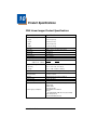
Chapter 10 - Product Specifications
3200 Linear Imager Product Specifications .............. 10-1
Chapter 11 - Maintenance
Repairs ...................................................................... 11-1
Maintenance.............................................................. 11-1
Cleaning the Device ............................................ 11-1
Inspecting Cords and Connectors ....................... 11-1
Replacing the Interface Cable ............................. 11-2
Troubleshooting ........................................................ 11-2
Chapter 12 - Customer Support
Technical Assistance ................................................ 12-1
Online Technical Assistance ............................... 12-1
Product Service and Repair ...................................... 12-2
Online Product Service and Repair Assistance... 12-3
Limited Warranty ....................................................... 12-3
Appendix A
Symbology Chart......................................................... A-1
ASCII Conversion Chart (Code Page 1252) ............... A-2
Code Page Mapping of Printed barcodes ................... A-4
v
vi
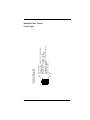
3200 Imager Identification
Item Number,
Serial Number and
Compliance
Information
location
1
Getting Started
About This Manual
This User’s Guide provides installation and programming instructions for the
3200 linear imager. Product specifications, dimensions, warranty, and customer
support information are also included.
Honeywell barcode imagers are factory programmed for the most common
terminal and communications settings. If you need to change these settings,
programming is accomplished by scanning the barcodes in this guide.
An asterisk (*) next to an option indicates the default setting.
Unpacking the Imager
After you open the shipping carton containing the 3200 linear imager, take the
following steps:
• Check to make sure everything you ordered is present.
• Save the shipping container for later storage or shipping.
• Check for damage during shipment. Report damage immediately to the
carrier who delivered the carton.
3200 Linear Imager Models
Note: The Honeywell 3200 linear imager may be used with two interfaces,
which are described in this User’s Guide. Refer to the chart below to
determine the models that can be used with your interface.
The chart below lists the 3200 linear imager models. “04” designates ivory and
“14” designates black.
Models
Primary Interfaces
3200-04USBE (ivory)
3200-14USBE (black)
USB
3200-04KBWE (ivory)
3200-14KBWE (black)
Keyboard wedge
3200 User’s Guide
1-1
Connecting the Imager with USB
Note: Honeywell recommends connecting the imager end of the cable first and
the host end second.
An imager can be connected to the USB port of a computer.
1. Connect the appropriate interface cable to the imager and to the computer.
2. The imager beeps.
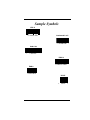
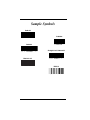
3. Verify the imager operation by scanning a barcode from the Sample
Symbols in the back of this manual.
For additional USB programming and technical information, refer to the
Honeywell “USB Application Note,” available at www.honeywellaidc.com.
USB PC or Macintosh Keyboard
The 3200 linear imagers are factory programmed for a USB interface. If this is
your interface and you do not need to modify the settings, skip to Chapter 3.
If you programmed the imager for a different terminal interface and you want to
change to a USB Keyboard (PC) or USB Keyboard (Mac), scan one of the
following codes to program the 3200 linear imager. Scanning these codes adds
a CR and selects the terminal ID (USB PC Keyboard - 124, USB Macintosh
Keyboard - 125).
USB Keyboard (PC)
USB Keyboard (Mac)
1-2
3200 User’s Guide
Plug and Play
Plug and Play barcodes provide instant imager set up for commonly used
interfaces.
Note: After you scan one of the codes, power cycle the host terminal to have the
interface in effect.
Connecting the Imager When Powered by Host
(Keyboard Wedge)
An imager can be connected between the keyboard and PC as a “keyboard
wedge,” plugged into the serial port or connected to a portable data terminal.
The following is an example of a keyboard wedge connection:
1. Turn off power to the terminal/computer.
2. Disconnect the keyboard cable from the back of the terminal/computer.
3. Connect the appropriate interface cable to the imager and to the terminal/
computer.
4. Turn the terminal/computer power back on.
Note: You will not hear a power-up beep because the 3200 linear imager is
factory defaulted to a USB connection. You must scan the IBM PC AT
and Compatibles with CR suffix barcode on page 1-4 to enable keyboard
wedge ability.
Verify the imager operation by scanning a barcode from the Sample Symbols in
the back of this manual. The imager beeps once.
3200 User’s Guide
1-3
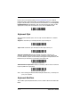
Keyboard Wedge Connection
Scanning the barcode below allows operation of the 3200 linear imager as a
keyboard wedge interface to an IBM PC AT with a U. S. keyboard.
If you programmed the imager for a different terminal interface and you want to
change to an IBM PC AT and compatibles keyboard wedge interface, scan the
barcode below.
Note: The following barcode also programs a carriage return (CR) suffix.
IBM PC AT and Compatibles
with CR suffix
Laptop Direct Connect
For most laptops, scanning the Laptop Direct Connect barcode allows
operation of the imager in parallel with the integral keyboard. The following
Laptop Direct Connect barcode selects terminal ID 03, programs a carriage
return (CR) suffix and turns on Emulate External Keyboard (page 2-4).
Laptop Direct Connect
with CR suffix
Connecting the Imager with RS-232 Serial Port
1. Turn off power to the terminal/computer.
2. Connect the appropriate interface cable to the imager.
1-4
3200 User’s Guide
Note: For the imager to work properly, you must have the correct cable for your
type of terminal/computer.
3. Plug the serial connector into the serial port on your computer. Tighten the
two screws to secure the connector to the port.
4. Connect the power supply and plug into an outlet.
5. Turn the terminal/computer power back on.
Note: You will not hear a power-up beep because the 3200 linear imager is
factory defaulted to a USB connection. You must scan the RS-232
Interface barcode below to enable RS-232 ability.
All communication parameters between the imager and terminal must match for
correct data transfer through the serial port using RS-232 protocol. Scanning the
RS-232 interface barcode, programs the imager for an RS-232 interface at
38,400 baud, parity–none, 8 data bits, 1 stop bit, and adds a suffix of a CR LF.
RS-232 Interface
Refer to page 2-6 for additional RS-232 configuration settings.
3200 User’s Guide
1-5
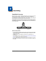
Reading Techniques
The imager has a bright red aiming beam that corresponds to its horizontal field
of view. The aiming beam should be centered horizontally over the barcode; it
will not read if the aiming beam is in any other direction.
Good Technique
Bad Technique
Bad Technique
The best focus point for reading most code densities is about 5 inches (12.7 cm)
from the unit. To read a single barcode or multiple barcodes (on a page or on
an object), hold the imager at an appropriate distance from the target, pull the
trigger, and center the aiming beam on the barcode.
Resetting the Standard Product Defaults
If you aren’t sure what programming options are in your imager, or you’ve
changed some options and want the factory settings restored, scan the
Standard Product Default Settings barcode below.
Standard Product Default Settings
The Menu Commands starting on page 9-1 lists the factory default settings for
each of the commands (indicated by an asterisk (*) on the programming pages).
1-6
3200 User’s Guide
2
Terminal Interfaces
Terminal ID
If your interface is not a standard PC AT, refer to Terminal ID, beginning on page
2-1 and locate the Terminal ID number for your PC. Scan the Terminal ID
barcode below, then scan the numeric barcode(s) from the Programming Chart
inside the back cover of this manual to program the imager for your terminal ID.
Scan Save to save your selection.
For example, an IBM AT terminal has a Terminal ID of 003. You would scan the
Terminal ID barcode, then 0, 0, 3 from the Programming Chart inside the back
cover of this manual, then Save. If you make an error while scanning the digits
(before scanning Save), scan the Discard code on the Programming Chart, scan
the Terminal ID barcode, scan the digits, and the Save code again.
Terminal ID
Save
Note: After scanning one of these codes, you must power cycle your computer.
3200 User’s Guide
2-1
Supported Terminals
Terminal
RS-232 TTL
USB PC Keyboard
USB Mac Keyboard
Model(s)
Terminal ID
000
124 *
125
* Factory default
2-2
3200 User’s Guide
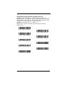
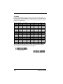
Keyboard Country
Scan the appropriate country code below to program the keyboard for your
country. As a general rule, the following characters are supported, but need
special care for countries other than the United States:
@ | $ # { } [ ] = / ‘ \ < > ~
* United States
Belgium
Denmark
Finland
France
Germany/Austria
Great Britain
Italy
Norway
Spain
Switzerland
3200 User’s Guide
2-3
Please refer to Honeywell website (www.honeywellaidc.com) for complete
keyboard country support information and applicable interfaces. If you need to
program a keyboard for a country other than one listed above, scan the Program
Keyboard Country barcode below, then scan the numeric barcode(s) for the
appropriate country from the inside back cover, then the Save barcode.
Program Keyboard Country
Keyboard Style
This programs keyboard styles, such as Caps Lock and Shift Lock. Default =
Regular.
Regular is used when you normally have the Caps Lock key off.
* Regular
Caps Lock is used when you normally have the Caps Lock key on.
Caps Lock
Autocaps via NumLock barcode should be scanned in countries (e.g.,
Germany, France) where the Caps Lock key cannot be used to toggle Caps
Lock. The NumLock option works similarly to the regular Auotcaps, but uses the
NumLock key to retrieve the current state of the Caps Lock.
Autocaps via NumLock
Emulate External Keyboard should be scanned if you do not have an external
keyboard (IBM AT or equivalent).
Emulate External Keyboard
Note: After scanning the Emulate External Keyboard barcode, you must power
cycle your computer.
Keyboard Modifiers
This modifies special keyboard features, such as CTRL+ ASCII codes and Turbo
Mode.
2-4
3200 User’s Guide
Control + ASCII Mode On: The imager sends key combinations for ASCII
control characters for values 00-1F. Refer to Keyboard Function
Relationships, page 7-1 for CTRL+ ASCII Values. Default = Off
Control + ASCII Mode On
* Control + ASCII Mode Off
Numeric Keypad Mode: Sends numeric characters as if entered from a
numeric keypad. Default = Off
Numeric Keypad Mode On
* Numeric Keypad Mode Off
Automatic Direct Connect Mode: This selection can be used if you have an
IBM AT style terminal and the system is dropping characters. Default = Off
Automatic Direct
Connect Mode On
* Automatic Direct Connect
Mode Off
3200 User’s Guide
2-5
RS-232 Baud Rate
Baud Rate sends the data from the imager to the terminal at the specified rate.
The host terminal must be set for the same baud rate as the imager.
Default = 38,400.
300
600
1200
2400
4800
9600
19200
* 38400
57,600
2-6
3200 User’s Guide
RS-232 Word Length: Data Bits, Stop Bits, and Parity
Data Bits sets the word length at 7 or 8 bits of data per character. If an
application requires only ASCII Hex characters 0 through 7F decimal (text, digits,
and punctuation), select 7 data bits. For applications which require use of the
full ASCII set, select 8 data bits per character. Default = 8.
Stop Bits sets the stop bits at 1 or 2. Default = 1.
Parity provides a means of checking character bit patterns for validity.
Default = None.
7 Data, 1 Stop, Parity Even
7 Data, 1 Stop, Parity None
7 Data, 1 Stop, Parity Odd
7 Data, 2 Stop, Parity Even
7 Data, 2 Stop Parity None
7 Data, 2 Stop, Parity Odd
8 Data, 1 Stop, Parity Even
* 8 Data, 1 Stop, Parity None
8 Data, 1 Stop, Parity Odd
3200 User’s Guide
2-7
RS-232 Handshaking
RS-232 handshaking is a set of rules concerning the exchange of data between
serially communicating devices. Default = RTS/CTS, XON/XOFF and ACK/
NAK Off.
RTS/CTS On
* RTS/CTS Off
XON/XOFF On
* XON/OFF Off
ACK/NAK On
* ACK/NAK Off
2-8
3200 User’s Guide
3
Output
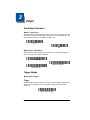
Good Read Indicators
Beeper – Good Read
The beeper may be programmed On or Off in response to a good read. Turning
this option off, only turns off the beeper response to a good read indication. All
error and menu beeps are still audible. Default = On.
* On
Off
Beeper Pitch – Good Read
The beeper pitch codes modify the pitch (frequency) of the beep the imager
emits on a good read. Default = Medium.
Low (1600 Hz)
* Medium (2550 Hz)
High (4200 Hz)
Trigger Modes
Manual/Serial Trigger
Trigger
The following barcodes will allow you to use the reader in Manual Trigger mode
(need to press the trigger to read) or Automatic Trigger mode (the beam is
always on).
* Manual/Serial Trigger
3200 User’s Guide
3-1
Automatic Trigger
The imager scans continuously at full power with illumination fully on.
Automatic Trigger
Reread Delay
This sets the time period before the imager can read the same barcode a second
time. Setting a reread delay protects against accidental rereads of the same
barcode. Longer delays are effective in minimizing accidental rereads at POS
(point of sale). Use shorter delays in applications where repetitive barcode
scanning is required. Default = Medium.
Reread Delay only works when in automatic trigger mode or presentation mode
(see page 3-2).
Short (500 ms)
* Medium (750 ms)
Long (1000 ms)
Extra Long (2000 ms)
3-2
3200 User’s Guide
4
Data Editing
Prefix/Suffix Overview
When a barcode is scanned, additional information is sent to the host computer
along with the barcode data. This group of barcode data and additional,
user-defined data is called a “message string.” The selections in this section are
used to build the user-defined data into the message string.
Prefix and Suffix characters are data characters that can be sent before and after
scanned data. You can specify if they should be sent with all symbologies, or
only with specific symbologies. The following illustration shows the breakdown
of a message string:
Prefix
1-11
alpha numeric
characters
Scanned Data
variable length
Suffix
1-11
alpha numeric
characters
Points to Keep In Mind
• It is not necessary to build a message string. The selections in this chapter
are only used if you wish to alter the default settings. Default prefix = None.
Default suffix = None.
• A prefix or suffix may be added or cleared from one symbology or all
symbologies.
• You can add any prefix or suffix from the ASCII Conversion Chart (Code Page
1252) on page A-2, plus Code I.D. and AIM I.D.
• You can string together several entries for several symbologies at one time.
• Enter prefixes and suffixes in the order in which you want them to appear on
the output.
3200 User’s Guide
4-1
To Add a Prefix or Suffix:
Step 1. Scan the Add Prefix or Add Suffix symbol (page 4-3).
Step 2. Determine the 2 digit Hex value from the Symbology Chart (included in
the ) for the symbology to which you want to apply the prefix or suffix.
For example, for Code 128, Code ID is “j” and Hex ID is “6A”.
Step 3. Scan the 2 hex digits from the Programming Chart inside the back
cover of this manual or scan 9, 9 for all symbologies.
Step 4. Determine the hex value from the ASCII Conversion Chart (Code Page
1252) on page A-2, for the prefix or suffix you wish to enter.
Step 5. Scan the 2 digit hex value from the Programming Chart inside the back
cover of this manual.
Step 6. Repeat Steps 4 and 5 for every prefix or suffix character.
Step 7. To add the Code I.D., scan 5, C, 8, 0.
To add AIM I.D., scan 5, C, 8, 1.
To add a backslash (\), scan 5, C, 5, C.
Note: To add a backslash (\) as in Step 7, you must scan 5C twice – once to
create the leading backslash and then to create the backslash itself.
Step 8. Scan Save to exit and save, or scan Discard to exit without saving.
Repeat Steps 1-6 to add a prefix or suffix for another symbology.
Example: Add a Suffix to a specific symbology
To send a CR (carriage return)Suffix for UPC only:
Step 1. Scan Add Suffix.
Step 2. Determine the 2 digit hex value from the Symbology Chart (included in
the ) for UPC.
Step 3. Scan 6, 3 from the Programming Chart inside the back cover of this
manual.
Step 4. Determine the hex value from the ASCII Conversion Chart (Code Page
1252) on page A-2, for the CR (carriage return).
Step 5. Scan 0, D from the Programming Chart inside the back cover of this
manual.
Step 6. Scan Save, or scan Discard to exit without saving.
4-2
3200 User’s Guide
To Clear One or All Prefixes or Suffixes:
You can clear a single prefix or suffix, or clear all prefixes/suffixes for a
symbology. When you Clear One Prefix (Suffix), the specific character you
select is deleted from the symbology you want. When you Clear All Prefixes
(Suffixes), all the prefixes or suffixes for a symbology are deleted.
Step 1. Scan the Clear One Prefix or Clear One Suffix symbol.
Step 2. Determine the 2 digit Hex value from the Symbology Chart (included in
the ) for the symbology from which you want to clear the prefix or suffix.
Step 3. Scan the 2 digit hex value from the Programming Chart inside the back
cover of this manual or scan 9, 9 for all symbologies.
Your change is automatically saved.
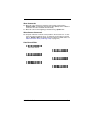
To Add a Carriage Return Suffix to all Symbologies
Scan the following barcode if you wish to add a carriage return suffix to all
symbologies at once. This action first clears all current suffixes, then programs
a carriage return suffix for all symbologies.
Add CR Suffix
All Symbologies
Prefix Selections
Add Prefix
Clear One Prefix
Clear All Prefixes
3200 User’s Guide
4-3
Suffix Selections
Add Suffix
Clear One Suffix
Clear All Suffixes
Function Code Transmit
When this selection is enabled and function codes are contained within the
scanned data, the imager transmits the function code to the terminal. Charts of
these function codes are provided in Supported Interface Keys starting on
page 7-3. When the imager is in keyboard wedge mode, the scan code is
converted to a key code before it is transmitted. Default = Enable.
* Enable
Disable
Intercharacter, Interfunction, and Intermessage
Delays
Some terminals drop information (characters) if data comes through too quickly.
Intercharacter, interfunction, and intermessage delays slow the transmission of
data, increasing data integrity.
Each delay is composed of a 5 millisecond step. You can program up to 99 steps
(of 5 ms each) for a range of 0-495 ms.
4-4
3200 User’s Guide
Intercharacter Delay
An intercharacter delay of up to 495 milliseconds may be placed between the
transmission of each character of scanned data. Scan the Intercharacter Delay
barcode below, then scan the number of milliseconds and the SAVE barcode
using the Programming Chart inside the back cover of this manual.
Prefix
Scanned Data
1
2
3
4
Suffix
5
Intercharacter Delay
Intercharacter Delay
To remove this delay, scan the Intercharacter Delay barcode, then set the
number of steps to 0. Scan the SAVE barcode using the Programming Chart
inside the back cover of this manual.
Note: Intercharacter delays are not supported in USB serial emulation.
Interfunction Delay
An interfunction delay of up to 495 milliseconds may be placed between the
transmission of each segment of the message string. Scan the Interfunction
Delay barcode below, then scan the number of milliseconds and the SAVE
barcode using the Programming Chart inside the back cover of this manual.
Prefix
STX
1
Scanned Data
HT
2 3 4 5
Suffix
CR
LF
Interfunction Delays
Interfunction Delay
To remove this delay, scan the Interfunction Delay barcode, then set the
number of steps to 0. Scan the SAVE barcode using the Programming Chart
inside the back cover of this manual.
3200 User’s Guide
4-5
Intermessage Delay
An intermessage delay of up to 495 milliseconds may be placed between each
scan transmission. Scan the Intermessage Delay barcode below, then scan
the number of milliseconds and the SAVE barcode using the Programming Chart
inside the back cover of this manual.
1st Scan Transmission 2nd Scan Transmission
Intermessage Delay
Intermessage Delay
To remove this delay, scan the Intermessage Delay barcode, then set the
number of steps to 0. Scan the SAVE barcode using the Programming Chart
inside the back cover of this manual.
4-6
3200 User’s Guide
5
Data Formatting
Data Format Editor Introduction
You may use the Data Format Editor to change the imager’s output. For
example, you can use the Data Format Editor to insert characters at certain
points in barcode data as it is scanned. The selections in the following pages
are used only if you wish to alter the output. Default Data Format setting = None.
Normally, when you scan a barcode, it gets outputted automatically; however
when you do a format, you must use a “send” command (see Send Commands
on page 5-2) within the format program to output data.
Multiple formats may be programmed into the imager. They are stacked in the
order in which they are entered. However, the following list presents the order
in which formats are applied:
1.
2.
3.
4.
5.
6.
7.
8.
Specific Term ID, Actual Code ID, Actual Length
Specific Term ID, Actual Code ID, Universal Length
Specific Term ID, Universal Code ID, Actual Length
Specific Term ID, Universal Code ID, Universal Length
Universal Term ID, Actual Code ID, Actual Length
Universal Term ID, Actual Code ID, Universal Length
Universal Term ID, Universal Code ID, Actual Length
Universal Term ID, Universal Code ID, Universal Length
If you have changed data format settings, and wish to clear all formats and return
to the factory defaults, scan the Default Data Format code on page 5-3.
To Add a Data Format
Step 1. Scan the Enter Data Format symbol (page 5-3).
Step 2. Terminal Type
Refer to the Supported Terminals Chart (page 2-2) and locate the Terminal ID number for your PC. Scan three numeric barcodes on the
inside back cover to program the imager for your terminal ID (you must
enter 3 digits). For example, scan 0 0 0 for an RS-232 TTL.
Note: The wildcard for all terminal types is 0099.
Step 3. Code I.D.
In the , find the symbology to which you want to apply the data format.
Locate the Hex value for that symbology and scan the 2 digit hex value
from the Programming Chart inside the back cover of this manual.
Step 4. Length
Specify what length (up to 9999 characters) of data will be acceptable
for this symbology. Scan the four digit data length from the Program-
3200 User’s Guide
5-1
ming Chart inside the back cover of this manual. (Note: 50 characters
is entered as 0050. 9999 is a universal number, indicating all lengths.)
Step 5. Editor Commands
Refer to the Format Editor Commands Chart (page 5-2). Scan the
symbols that represent the command you want to enter. 94 alphanumeric characters may be entered for each symbology data format.
Step 6. Scan Save from the Programming Chart inside the back cover of this
manual to save your entries.
Other Programming Selections
• Clear One Data Format
This deletes one data format for one symbology. If you are clearing the
primary format, scan 0 from the Programming Chart inside the back cover of
this manual. If you are clearing an alternate format, scan 1, 2, or 3, depending
on the alternate format you are clearing. Scan the Terminal Type (refer to the
Supported Terminals Chart on page 2-2), Code I.D. (refer to the Symbology
Chart on page A-1), and the barcode data length for the specific data format
that you want to delete. All other formats remain unaffected.
• Save from the Programming Chart inside the back cover of this manual
This exits, saving any Data Format changes.
• Discard from the Programming Chart inside the back cover of this manual
This exits without saving any Data Format changes.
Data Format Editor Commands
Send Commands
F1 Send all characters followed by “xx” key or function code, starting from current cursor position. Syntax = F1xx (xx stands for the hex value for an
ASCII code, see ASCII Conversion Chart (Code Page 1252) on page A-2.)
F2 Send “nn” characters followed by “xx” key or function code, starting from
current cursor position. Syntax = F2nnxx (nn stands for the numeric value
(00-99) for the number of characters and xx stands for the hex value for an
ASCII code. See ASCII Conversion Chart (Code Page 1252) on page A-2.)
F3 Send up to but not including “ss” character (Search and Send) starting from
current cursor position, leaving cursor pointing to “ss” character followed by
“xx” key or function code. Syntax = F3ssxx (ss and xx both stand for the
hex values for ASCII codes, see ASCII Conversion Chart (Code Page
1252) on page A-2.)
F4 Send “xx” character “nn” times (Insert) leaving cursor in current cursor position. Syntax = F4xxnn (xx stands for the hex value for an ASCII code, see
ASCII Conversion Chart (Code Page 1252) on page A-2, and nn is the
numeric value (00-99) for the number of times it should be sent.)
5-2
3200 User’s Guide
Move Commands
F5 Move the cursor ahead “nn” characters from current cursor position.
Syntax = F5nn (nn stands for the numeric value (00-99) for the number of
characters the cursor should be moved ahead.)
F7 Move the cursor to the beginning of the data string. Syntax = F7.
Miscellaneous Commands
FE Compare character in current cursor position to the character “xx.” If characters are equal, increment cursor. If characters are not equal, no format
match. Syntax = FExx (xx stands for the hex value for an ASCII code, see
ASCII Conversion Chart (Code Page 1252) on page A-2.)
Data Format Editor
Enter Data Format
* Default Data Format
Clear One Data Format
Clear All Data Formats
Save
Discard
3200 User’s Guide
5-3
Data Formatter
When Data Formatter is turned off, the barcode data is output to the host as read
(including prefixes and suffixes). Choose one of the following options. Default
= Data Formatter On.
* Data Formatter On,
but Not Required
Data Formatter Off
When Data Formatter is required, all input data must conform to an edited format
or the imager does not transmit the input data to the host device.
Data Format On, Format Required
5-4
3200 User’s Guide
6
Symbologies
Introduction
This programming section contains the following menu selections. Refer to
Chapter 9 for settings and defaults.
• All Symbologies
• Interleaved 2 of 5
• China Post Code
• Matrix 2 of 5
• Codabar
• MSI
• Code 11
• Plessey Code
• Code 39
• RSS-14
• Code 32 Pharmaceutical (PARAF)
• Straight 2 of 5 IATA
(two-bar start/stop)
• Code 93
• Straight 2 of 5
Industrial (three-bar
start/stop)
• Code 128
• Telepen
• UPC-A/EAN-13 with Extended
Coupon Code
• UPC A
• EAN/JAN 8
• UPC E
All Symbologies
If you want to decode all the symbologies allowable for your imager, scan the All
Symbologies On code. If on the other hand, you want to decode only a
particular symbology, scan All Symbologies Off followed by the On symbol for
that particular symbology.
All Symbologies On
All Symbologies Off
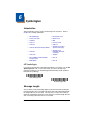
Message Length
You are able to set the valid reading length of some of the barcode symbologies.
If the data length of the scanned barcode doesn’t match the valid reading length,
the imager will issue an error beep. You may wish to set the same value for
minimum and maximum length to force the imager to read fixed length barcode
data. This helps reduce the chances of a misread.
3200 User’s Guide
6-1
EXAMPLE: Decode only those barcodes with a count of 9-20 characters.
Min. length = 09
Max. length = 20
EXAMPLE: Decode only those barcodes with a count of 15 characters.
Min. length = 15
Max. length = 15
For a value other than the minimum and maximum message length defaults,
scan the barcodes included in the explanation of the symbology, then scan the
digit value of the message length and Save barcodes on the Programming Chart
inside the back cover of this manual. The minimum and maximum lengths and
the defaults are included with the respective symbologies.
Codabar
<Default All Codabar Settings>
Codabar
* On
Off
Codabar Start/Stop Characters
Start/Stop characters identify the leading and trailing ends of the barcode. You
may either transmit, or not transmit Start/Stop characters.
Default = Don’t Transmit.
Transmit
* Don’t Transmit
Codabar Check Character
Codabar check characters are created using different “modulos.” You can
program the imager to read only Codabar barcodes with Modulo 16 check
characters. Default = No Check Character.
6-2
3200 User’s Guide
No Check Character indicates that the imager reads and transmits barcode
data with or without a check character.
When Check Character is set to Validate and Transmit, the imager will only
read Codabar barcodes printed with a check character, and will transmit this
character at the end of the scanned data.
When Check Character is set to Validate, but Don’t Transmit, the unit will only
read Codabar barcodes printed with a check character, but will not transmit the
check character with the scanned data.
* No Check Character
Validate Modulo 16, but
Don’t Transmit
Validate Modulo 16 and Transmit
Codabar Message Length
Scan the barcodes below to change the message length. Refer to Message
Length on page 6-1 for additional information. Minimum and Maximum
lengths = 2-60. Minimum Default = 4, Maximum Default = 60.
Minimum Message Length
Maximum Message Length
3200 User’s Guide
6-3
Code 39
< Default All Code 39 Settings >
Code 39
* On
Off
Code 39 Start/Stop Characters
Start/Stop characters identify the leading and trailing ends of the barcode. You
may either transmit, or not transmit Start/Stop characters. Default = Don’t
Transmit.
Transmit
* Don’t Transmit
6-4
3200 User’s Guide
Code 39 Check Character
No Check Character indicates that the imager reads and transmits barcode
data with or without a check character.
When Check Character is set to Validate, but Don’t Transmit, the unit only
reads Code 39 barcodes printed with a check character, but will not transmit the
check character with the scanned data.
When Check Character is set to Validate and Transmit, the imager only reads
Code 39 barcodes printed with a check character, and will transmit this character
at the end of the scanned data. Default = No Check Character.
* No Check Character
Validate, but Don’t Transmit
Validate and Transmit
Code 39 Message Length
Scan the barcodes below to change the message length. Refer to Message
Length on page 6-1 for additional information. Minimum and Maximum
lengths = 0-48. Minimum Default = 0, Maximum Default = 48.
Minimum Message Length
Maximum Message Length
Code 32 Pharmaceutical (PARAF)
Code 32 Pharmaceutical is a form of the Code 39 symbology used by Italian
pharmacies. This symbology is also known as PARAF.
On
* Off
3200 User’s Guide
6-5
Full ASCII
If Full ASCII Code 39 decoding is enabled, certain character pairs within the
barcode symbol will be interpreted as a single character. For example: $V will
be decoded as the ASCII character SYN, and /C will be decoded as the ASCII
character #. Default = Off.
NUL %U
DLE $P
SP
SPACE 0
0
@
%V
P
P
‘
%W p
+P
SOH $A
DC1 $Q
!
/A
1
1
A
A
Q
Q
a
+A
q
+Q
STX $B
DC2 $R
“
/B
2
2
B
B
R
R
b
+B
r
+R
ETX $C
DC3 $S
#
/C
3
3
C
C
S
S
c
+C
s
+S
EOT $D
DC4 $T
$
/D
4
4
D
D
T
T
d
+D
t
+T
ENQ $E
NAK $U
%
/E
5
5
E
E
U
U
e
+E
u
+U
ACK $F
SYN $V
&
/F
6
6
F
F
V
V
f
+F
v
+V
BEL $G
ETB $W
‘
/G
7
7
G
G
W
W
g
+G
w
+W
BS
$H
CAN $X
(
/H
8
8
H
H
X
X
h
+H
x
+X
HT
$I
EM
$Y
)
/I
9
9
I
I
Y
Y
i
+I
y
+Y
LF
$J
SUB $Z
*
/J
:
/Z
J
J
Z
Z
j
+J
z
+Z
VT
$K
ESC %A
+
/K
;
%F
K
K
[
%K
k
+K
{
%P
FF
$L
FS
%B
,
/L
<
%G L
L
\
%L
l
+L
|
%Q
CR
$M
GS
%C
-
-
=
%H
M
M
]
%M m
+M
}
%R
SO
$N
RS
%D
.
.
>
%I
N
N
^
%N
n
+N
~
%S
SI
$O
US
%E
/
/O
?
%J
O
O
_
%O o
+O
DEL %T
Character pairs /M and /N decode as a minus sign and period respectively.
Character pairs /P through /Y decode as 0 through 9.
Full ASCII On
* Full ASCII Off
6-6
3200 User’s Guide
Code 39 Code Page
Code pages define the mapping of character codes to characters. If the data
received does not display with the proper characters, it may be because the
barcode being scanned was created using a code page that is different from the
one the host program is expecting. If this is the case, scan the barcode below,
select the code page with which the barcodes were created from the chart, Code
Page Mapping of Printed barcodes on page A-4, and scan the value and the
SAVE barcode from the Programming Chart inside the back cover of this
manual. The data characters should then appear properly.
Code 39 Code Page
Interleaved 2 of 5
< Default All Interleaved 2 of 5 Settings >
Interleaved 2 of 5
* On
Off
Check Digit
No Check Digit indicates that the imager reads and transmits barcode data with
or without a check digit.
3200 User’s Guide
6-7
When Check Digit is set to Validate, but Don’t Transmit, the unit only reads
Interleaved 2 of 5 barcodes printed with a check digit, but will not transmit the
check digit with the scanned data.
When Check Digit is set to Validate and Transmit, the imager only reads
Interleaved 2 of 5 barcodes printed with a check digit, and will transmit this digit
at the end of the scanned data. Default = No Check Digit.
* No Check Digit
Validate, but Don’t Transmit
Validate and Transmit
Interleaved 2 of 5 Message Length
Scan the barcodes below to change the message length. Refer to Message
Length on page 6-1 for additional information. Minimum and Maximum
lengths = 2-80. Minimum Default = 4, Maximum Default = 80.
Minimum Message Length
Maximum Message Length
6-8
3200 User’s Guide
Code 93
< Default All Code 93 Settings >
Code 93
* On
Off
Code 93 Message Length
Scan the barcodes below to change the message length. Refer to Message
Length on page 6-1 for additional information. Minimum and Maximum
lengths = 0-80. Minimum Default = 0, Maximum Default = 80.
Minimum Message Length
Maximum Message Length
Code 93 Code Page
Code pages define the mapping of character codes to characters. If the data
received does not display with the proper characters, it may be because the
barcode being scanned was created using a code page that is different from the
one the host program is expecting. If this is the case, scan the barcode below,
select the code page with which the barcodes were created from the chart, Code
Page Mapping of Printed barcodes on page A-4, and scan the value and the
SAVE barcode from the Programming Chart inside the back cover of this
manual. The data characters should then appear properly.
Code 93 Code Page
3200 User’s Guide
6-9
Straight 2 of 5 Industrial (three-bar start/stop)
<Default All Straight 2 of 5 Settings>
Straight 2 of 5 Industrial
On
* Off
Straight 2 of 5 Industrial Message Length
Scan the barcodes below to change the message length. Refer to Message
Length on page 6-1 for additional information. Minimum and Maximum
lengths = 1-48. Minimum Default = 4, Maximum Default = 48.
Minimum Message Length
Maximum Message Length
Straight 2 of 5 IATA (two-bar start/stop)
<Default All Code IATA 2 of 5 Settings>
6 - 10
3200 User’s Guide
Straight 2 of 5 IATA
On
* Off
Straight 2 of 5 IATA Message Length
Scan the barcodes below to change the message length. Refer to Message
Length on page 6-1 for additional information. Minimum and Maximum
lengths = 1-48. Minimum Default = 4, Maximum Default = 48.
Minimum Message Length
Maximum Message Length
Matrix 2 of 5
<Default All Matrix 2 of 5 Settings>
Matrix 2 of 5
On
* Off
3200 User’s Guide
6 - 11
Matrix 2 of 5 Message Length
Scan the barcodes below to change the message length. Refer to Message
Length on page 6-1 for additional information. Minimum and Maximum
lengths = 1-80. Minimum Default = 4, Maximum Default = 80.
Minimum Message Length
Maximum Message Length
Code 11
<Default All Code 11 Settings>
Code 11
On
* Off
Check Digits Required
This option sets whether 1 or 2 check digits are required with Code 11 barcodes.
Default = Two Check Digits.
One Check Digit
* Two Check Digits
6 - 12
3200 User’s Guide
Code 11 Message Length
Scan the barcodes below to change the message length. Refer to Message
Length on page 6-1 for additional information. Minimum and Maximum
lengths = 1-80. Minimum Default = 4, Maximum Default = 80.
Minimum Message Length
Maximum Message Length
Code 128
<Default All Code 128 Settings>
Code 128
* On
Off
ISBT 128 Concatenation
In 1994 the International Society of Blood Transfusion (ISBT) ratified a standard
for communicating critical blood information in a uniform manner. The use of
ISBT formats requires a paid license. The ISBT 128 Application Specification
describes 1) the critical data elements for labeling blood products, 2) the current
recommendation to use Code 128 due to its high degree of security and its
space-efficient design, 3) a variation of Code 128 that supports concatenation of
neighboring symbols, and 4) the standard layout for barcodes on a blood product
label. Use the barcodes below to turn concatenation on or off. Default =Off.
On
* Off
3200 User’s Guide
6 - 13
Code 128 Message Length
Scan the barcodes below to change the message length. Refer to Message
Length on page 6-1 for additional information. Minimum and Maximum
lengths = 0-80. Minimum Default = 0, Maximum Default = 80.
Minimum Message Length
Maximum Message Length
Code 128 Code Page
Code pages define the mapping of character codes to characters. If the data
received does not display with the proper characters, it may be because the
barcode being scanned was created using a code page that is different from the
one the host program is expecting. If this is the case, scan the barcode below,
select the code page with which the barcodes were created from the chart, Code
Page Mapping of Printed barcodes on page A-4, and scan the value and the
SAVE barcode from the Programming Chart inside the back cover of this
manual. The data characters should then appear properly.
Code 128 Code Page
Code 128 Function Code Transmit
By default, Code 128 function codes are not transmitted with Code 128 barcode
data. However, if you wish to transmit Code 128 function codes with the barcode
data, scan the Function Codes On barcode, below.
* Function Codes Off
Function Codes On
Telepen
<Default All Telepen Settings>
6 - 14
3200 User’s Guide
Telepen
On
* Off
Telepen Output
Using AIM Telepen Output, the imager reads symbols with start/stop pattern 1
and decodes them as standard full ASCII (start/stop pattern 1). When Original
Telepen Output is selected, the imager reads symbols with start/stop pattern 1
and decodes them as compressed numeric with optional full ASCII (start/stop
pattern 2). Default = AIM Telepen Output.
* AIM Telepen Output
Original Telepen Output
Telepen Message Length
Scan the barcodes below to change the message length. Refer to Message
Length on page 6-1 for additional information. Minimum and Maximum
lengths = 1-60. Minimum Default = 1, Maximum Default = 60.
Minimum Message Length
Maximum Message Length
3200 User’s Guide
6 - 15
UPC A
<Default All UPC A Settings>
UPC A
* On
Off
UPC A Check Digit
This selection allows you to specify whether the check digit should be
transmitted at the end of the scanned data or not. Default = On.
* On
Off
UPC A Number System
The numeric system digit of a U.P.C. symbol is normally transmitted at the
beginning of the scanned data, but the unit can be programmed so it will not
transmit it. Default = On.
* On
Off
UPC A Addenda
6 - 16
3200 User’s Guide
This selection adds 2 or 5 digits to the end of all scanned UPC A data.
Default = Off for both 2 Digit and 5 Digit Addenda.
2 Digit Addenda On
* 2 Digit Addenda Off
5 Digit Addenda On
* 5 Digit Addenda Off
UPC A Addenda Required
When Addenda Required is set to on, the imager will only read UPC A barcodes
that have addenda. Default = Not Required.
Required
* Not Required
UPC-A/EAN-13
with Extended Coupon Code
Use the following codes to enable or disable UPC-A and EAN-13 with Extended
Coupon Code. Default = On.
* On
Off
3200 User’s Guide
6 - 17
UPC E
<Default All UPC E Settings>
UPC E0 and UPC E1
Most U.P.C. barcodes lead with the 0 number system. For these codes, use the
UPC E0 selection. If you need to read codes that lead with the 1 number system,
use the UPC E1 selection. Default = On (UPC E0) and Off (UPC E1).
* UPC E0 On
UPC E0 Off
UPC E1 On
* UPC E1 Off
UPC E0 and UPC E1 Expand
UPC E Expand expands the UPC E code to the 12 digit, UPC A format.
Default = Off.
On
* Off
UPC E0 and UPC E1 Addenda Required
When Addenda Required is set to on, the imager will only read UPC E barcodes
that have addenda. Default = Not Required.
Required
* Not Required
6 - 18
3200 User’s Guide
UPC E0 Check Digit
Check Digit specifies whether the check digit should be transmitted at the end of
the scanned data or not. Default = On.
* On
Off
UPC E0 Number System
The numeric system digit of a U.P.C. symbol is normally transmitted at the
beginning of the scanned data, but the unit can be programmed so it will not
transmit it. Default = On.
* On
Off
UPC E0 Addenda
This selection adds 2 or 5 digits to the end of all scanned UPC E data.
Default = Off for both 2 Digit and 5 Digit Addenda.
2 Digit Addenda On
* 2 Digit Addenda Off
5 Digit Addenda On
* 5 Digit Addenda Off
EAN/JAN 13
<Default All EAN/JAN Settings>
3200 User’s Guide
6 - 19
EAN/JAN 13
* On
Off
EAN/JAN 13 Check Digit
This selection allows you to specify whether the check digit should be
transmitted at the end of the scanned data or not. Default = On.
* On
Off
EAN/JAN 13 Addenda
This selection adds 2 or 5 digits to the end of all scanned EAN/JAN 13 data.
Default = Off for both 2 Digit and 5 Digit Addenda.
2 Digit Addenda On
* 2 Digit Addenda Off
5 Digit Addenda On
* 5 Digit Addenda Off
EAN/JAN 13 Addenda Required
When Addenda Required is set to on, the imager will only read EAN/JAN 13
barcodes that have addenda. Default = Not Required.
Required
* Not Required
6 - 20
3200 User’s Guide
EAN/JAN 13 Addenda Separator
When this feature is on, there is a space between the data from the barcode and
the data from the addenda. When turned off, there is no space.
Default = On.
* On
Off
Note: If you want to enable or disable EAN13 with Extended Coupon Code,
refer to UPC-A/EAN-13 with Extended Coupon Code on page 6-17.
ISBN Translate
This selection causes EAN-13 Bookland symbols to be translated into their
equivalent ISBN number format. Default = Off.
On
* Off
EAN/JAN 8
<Default All EAN/JAN 8 Settings>
EAN/JAN 8
* On
Off
3200 User’s Guide
6 - 21
EAN/JAN 8 Check Digit
This selection allows you to specify whether the check digit should be
transmitted at the end of the scanned data or not. Default = On.
* On
Off
EAN/JAN 8 Addenda
This selection adds 2 or 5 digits to the end of all scanned EAN/JAN 8 data.
Default = Off for both 2 Digit and 5 Digit Addenda.
2 Digit Addenda On
* 2 Digit Addenda Off
5 Digit Addenda On
* 5 Digit Addenda Off
EAN/JAN 8 Addenda Required
When Addenda Required is set to on, the imager will only read EAN/JAN 8
barcodes that have addenda. Default = Not Required.
Required
* Not Required
6 - 22
3200 User’s Guide
EAN/JAN 8 Addenda Separator
When this feature is on, there is a space between the data from the barcode and
the data from the addenda. When turned off, there is no space.
Default = On.
* On
Off
MSI
<Default All MSI Settings>
MSI
On
* Off
MSI Check Character
Different types of check characters are used with MSI barcodes. You can
program the imager to read MSI barcodes with Type 10 check characters.
Default = Validate Type 10, but Don’t Transmit.
When Check Character is set to Validate and Transmit, the imager will only
read MSI barcodes printed with the specified type check character, and will
transmit this character at the end of the scanned data.
When Check Character is set to Validate, but Don’t Transmit, the unit will only
read MSI barcodes printed with the specified type check character, but will not
transmit the check character with the scanned data.
* Validate Type 10, but Don’t
Transmit
Validate Type 10 and Transmit
3200 User’s Guide
6 - 23
MSI Message Length
Scan the barcodes below to change the message length. Refer to Message
Length on page 6-1 for additional information. Minimum and Maximum
lengths = 4-48. Minimum Default = 4, Maximum Default = 48.
Minimum Message Length
Maximum Message Length
Plessey Code
<Default All Plessey Code Settings>
Plessey Code
On
* Off
Plessey Message Length
Scan the barcodes below to change the message length. Refer to Message
Length on page 6-1 for additional information. Minimum and Maximum
lengths = 4-48. Minimum Default = 4, Maximum Default = 48.
Minimum Message Length
Maximum Message Length
RSS-14
< Default All RSS-14 Settings >
6 - 24
3200 User’s Guide
RSS-14
* On
Off
RSS Limited
< Default All RSS Limited Settings >
RSS Limited
* On
Off
RSS Expanded
< Default All RSS Expanded Settings >
3200 User’s Guide
6 - 25
RSS Expanded
* On
Off
RSS Expanded Message Length
Scan the barcodes below to change the message length. Refer to Message
Length on page 6-1 for additional information. Minimum and Maximum
lengths = 4-74. Minimum Default = 4, Maximum Default = 74.
Minimum Message Length
Maximum Message Length
EAN•UCC Emulation
The imager can automatically format the output from any EAN•UCC data carrier
to emulate what would be encoded in an equivalent UCC/EAN-128 or
RSS+Composite symbol. EAN•UCC data carriers include UPC-A and UPC-E,
EAN-13 and EAN-8, ITF-14, UCC/EAN-128, and EAN•UCC RSS and
Composites. If UCC/EAN-128 Emulation is selected, the AIM Symbology
Identifier will be reported as “]C1”. If RSS Emulation is selected, the AIM
Symbology Identifier will be reported as “]e0.” Any application that accepts
EAN•UCC data can be simplified since it only needs to recognize one data
carrier type. Default = EAN•UCC Emulation Off.
RSS Emulation
128 Emulation
* EAN•UCC Emulation Off
China Post Code
<Default All China Post Code Settings>
6 - 26
3200 User’s Guide
China Post Code
On
* Off
China Post Message Length
Scan the barcodes below to change the message length. Refer to Message
Length on page 6-1 for additional information. Minimum and Maximum
lengths = 2-80. Minimum Default = 4, Maximum Default = 80.
Minimum Message Length
Maximum Message Length
3200 User’s Guide
6 - 27
6 - 28
3200 User’s Guide
7
Interface Keys
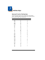
Keyboard Function Relationships
The following Keyboard Function Code, Hex/ASCII Value, and Full ASCII
“CTRL”+ relationships apply to all terminals that can be used with the imager.
Refer to page 2-5 enable Control + ASCII mode.
Function Code
HEX/ASCII Value
NUL
SOH
STX
ETX
EOT
ENQ
ACK
BEL
BS
HT
LF
VT
FF
CR
SO
SI
DLE
DC1
DC2
DC3
DC4
NAK
SYN
ETB
CAN
EM
SUB
ESC
FS
GS
RS
US
3200 User’s Guide
00
01
02
03
04
05
06
07
08
09
0A
0B
0C
0D
0E
0F
10
11
12
13
14
15
16
17
18
19
1A
1B
1C
1D
1E
1F
Full ASCII “CTRL” +
2
A
B
C
D
E
F
G
H
I
J
K
L
M
N
O
P
Q
R
S
T
U
V
W
X
Y
Z
[
\
]
6
-
7-1
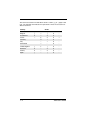
The last five characters in the Full ASCII “CTRL”+ column ( [ \ ] 6 - ), apply to US
only. The following chart indicates the equivalents of these five characters for
different countries.
Country
Codes
United States
[
\
]
6
-
Belgium
[
<
]
6
-
Scandinavia
8
<
9
6
-
France
^
8
$
6
=
Germany
Ã
+
6
-
Italy
\
+
6
-
Switzerland
<
..
6
-
United Kingdom
[
¢
]
6
-
Denmark
8
\
9
6
-
Norway
8
\
9
6
-
Spain
[
\
]
6
-
7-2
3200 User’s Guide
Supported Interface Keys
ASCII
NUL
SOH
STX
ETX
EOT
ENQ
ACK
BEL
BS
HT
LF
VT
FF
CR
SO
SI
DLE
DC1
DC2
DC3
DC4
NAK
SYN
ETB
CAN
EM
SUB
ESC
FS
GS
RS
US
HEX
00
01
02
03
04
05
06
07
08
09
0A
0B
0C
0D
0E
0F
10
11
12
13
14
15
16
17
18
19
1A
1B
1C
1D
1E
1F
IBM AT/XT and
PS/2 Compatibles,
WYSE PC/AT
Supported Keys
Reserved
Enter (KP)
Cap Lock
ALT make
ALT break
CTRL make
CTRL break
CR/Enter
Reserved
Tab
Reserved
Tab
Delete
CR/Enter
Insert
Escape
F11
Home
Print
Back Space
Back Tab
F12
F1
F2
F3
F4
F5
F6
F7
F8
F9
F10
IBM XTs and
Compatibles
Supported Keys
Reserved
CR/Enter
Caps Lock
Reserved
Reserved
Reserved
Reserved
CR/Enter
Reserved
Tab
Reserved
Tab
Delete
CR/Enter
Insert
Escape
Reserved
Home
Print
Back Space
Back Tab
Reserved
F1
F2
F3
F4
F5
F6
F7
F8
F9
F10
* IBM 3191/92, 3471/72, 3196/97, 3476/77, Telex (all models)
3200 User’s Guide
7-3
7-4
3200 User’s Guide
8
Utilities
To Add a Test Code I.D. Prefix to All Symbologies
This selection allows you to turn on transmission of a Code I.D. before the
decoded symbology. (See the Symbology Chart, included in the , page A-1) for
the single character code that identifies each symbology.) This action first clears
all current prefixes, then programs a Code I.D. prefix for all symbologies. This is
a temporary setting that will be removed when the unit is power cycled.
Add Code I.D. Prefix to
All Symbologies (Temporary)
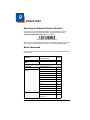
Show Software Revision
Scan the barcode below to output the current software revision, unit serial
number, and other product information.
Show Revision
Show Data Format
Scan the barcode below to show current data format settings.
Data Format Settings
Resetting the Standard Product Defaults
If you aren’t sure what programming options are in your imager, or you’ve
changed some options and want the standard product default settings restored,
scan the Standard Product Default Settings barcode below.
Standard Product Default Settings
The Menu Commands starting on page 9-1 lists the standard product default
settings for each of the commands (indicated by an asterisk (*) on the
programming pages).
3200 User’s Guide
8-1
8-2
3200 User’s Guide
9
Default Chart
Resetting the Standard Product Defaults
If you aren’t sure what programming options are in your imager, or you’ve
changed some options and want the factory settings restored, scan the
Standard Product Default Settings barcode below.
Standard Product Default Settings
The chart on the following pages lists the factory default settings for each of the
menu commands (indicated by an asterisk (*) on the programming pages).
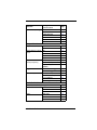
Menu Commands
The following chart lists all of the menu commands and the defaults and ranges
for each entry.
Selection
Factory Default Settings
Setting
* Indicates default
Page
Default
Terminal Interfaces
Terminal ID
USB PC Keyboard
2-2
Program Keyboard
Country
*USA
2-3
Belgium
2-3
Denmark
2-3
Finland
2-3
France
2-3
Germany/Austria
2-3
Great Britain
2-3
Italy
2-3
Norway
2-3
Spain
2-3
Switzerland
2-3
*Regular
2-4
Emulate External
Keyboard
2-4
Keyboard Style
3200 User’s Guide
9-1
Selection
Keyboard Modifiers
Setting
* Indicates default
Page
*Control + ASCII Off
2-5
Control + ASCII On
2-5
*Numeric Keypad Off
2-5
Numeric Keypad On
2-5
*Auto Direct Conn. Off
2-5
Auto Direct Conn. On
2-5
Serial Port Connection
RS-232
1-5
Baud Rate
300 BPS
2-6
600 BPS
2-6
1200 BPS
2-6
2400 BPS
2-6
4800 BPS
2-6
9600 BPS
2-6
19200 BPS
2-6
*38400 BPS
2-6
57600 BPS
2-6
7 Data, 1 Stop, Parity
Even
2-7
7 Data, 1 Stop, Parity
None
2-7
7 Data, 1 Stop, Parity
Odd
2-7
7 Data, 2 Stop, Parity
Even
2-7
7 Data, 2 Stop, Parity
None
2-7
7 Data, 2 Stop, Parity
Odd
2-7
8 Data, 1 Stop, Parity
Even
2-7
*8 Data, 1 Stop, Parity
None
2-7
8 Data, 1 Stop, Parity
Odd
2-7
Word Length: Data
Bits, Stop Bits, and
Parity
9-2
3200 User’s Guide
Selection
RS-232 Handshaking
Setting
* Indicates default
Page
*RTS/CTS Off
2-8
RTS/CTS On
2-8
*XON/XOFF Off
2-8
XON/XOFF On
2-8
*ACK/NAK Off
2-8
ACK/NAK On
2-8
Off
3-1
*On
3-1
Off
3-1
Low
3-1
Medium
3-1
*High
3-1
Low (1600) (min 400Hz)
3-1
*Medium (2550)
3-1
High (4200) (max
9000Hz)
3-1
*Manual/Serial Trigger
3-1
Automatic Trigger
3-2
Short (500 ms)
3-2
*Medium (750 ms)
3-2
Long (1000 ms)
3-2
Extra Long (2000 ms)
3-2
Output Selections
Beeper - Good Read
Beeper Volume - Good
Read
Beeper Pitch - Good
Read (Frequency)
Trigger Mode
Reread Delay
Prefix/Suffix Selections
Add CR Suffix to All Symbologies
4-3
Prefix
Add Prefix
4-3
Clear One Prefix
4-3
Clear All Prefixes
4-3
Suffix
3200 User’s Guide
Add Suffix
4-4
Clear One Suffix
4-4
Clear All Suffixes
4-4
9-3
Selection
Function Code Transmit
Setting
* Indicates default
Page
*Enable
4-4
Disable
4-4
Intercharacter Delay
4-5
Interfunction Delay
4-5
Intermessage Delay
4-6
Data Formatter Selections
Data Format Editor
*Default Data Format
(None)
5-3
Enter Data Format
5-3
Clear One Data Format
5-3
Clear All Data Formats
5-3
Off
5-4
*On, but Not Required
5-4
On, Required
5-4
All Symbologies
All Symbologies Off
6-1
All Symbologies On
6-1
Codabar
Default All Codabar
Settings
6-2
Codabar
Off
6-2
*On
6-2
Codabar Start/Stop
Char.
*Don’t Transmit
6-2
Transmit
6-2
Codabar Check Char.
*No Check Char.
6-3
Validate, But Don’t Transmit
6-3
Validate, and Transmit
6-3
Codabar Message
Length
Minimum (2 - 60) *4
6-3
Maximum (2 - 60) *60
6-3
Code 39
Default All Code 39
Settings
6-4
Code 39
Off
6-4
*On
6-4
Data Formatter
Symbologies
9-4
3200 User’s Guide
Selection
Setting
* Indicates default
Page
Code 39 Start/Stop
Char.
*Don’t Transmit
6-4
Transmit
6-4
Code 39 Check Char.
*No Check Char.
6-5
Validate, But Don’t
Transmit
6-5
Validate,
and Transmit
6-5
Code 39 Message
Length
Minimum (0 - 48) *0
6-5
Maximum (0 - 48) *48
6-5
Code 32 Pharmaceutical (PARAF)
*Off
6-5
On
6-5
Code 39 Full ASCII
*Off
6-6
On
6-6
Interleaved 2 of 5
Default All Interleaved
2 of 5 Settings
6-7
Interleaved 2 of 5
Off
6-7
*On
6-7
*No Check Char.
6-8
Validate, But Don’t
Transmit
6-8
Interleaved 2 of 5
Check Digit
Validate, and Transmit
6-8
Interleaved 2 of 5 Message Length
Minimum (2 - 80) *4
6-8
Maximum (2 - 80) *80
6-8
Code 93
Default All Code 93
Settings
6-9
Code 93
Off
6-9
*On
6-9
Code 93 Message
Length
Minimum (0 - 80) *0
6-9
Maximum (0 - 80) *80
6-9
Straight 2 of 5 Industrial
Default All Straight 2 of 5
Settings
6-10
Straight 2 of 5 Industrial
*Off
6-10
On
6-10
3200 User’s Guide
9-5
Selection
Setting
* Indicates default
Page
Straight 2 of 5 Industrial Message Length
Minimum (1 - 48) *4
6-10
Maximum (1 - 48) *48
6-10
Straight 2 of 5 IATA
Default All Straight 2 of 5
IATA
Settings
6-11
Straight 2 of 5 IATA
*Off
6-11
On
6-11
Straight 2 of 5 IATA
Message Length
Minimum (1 - 48) *4
6-11
Maximum (1 - 48) *48
6-11
Matrix 2 of 5
Default All Matrix 2 of 5
Settings
6-11
Matrix 2 of 5
*Off
6-11
On
6-11
Matrix 2 of 5 Message
Length
Minimum (1 - 80) *4
6-12
Maximum (1 - 80) *80
6-12
Code 11
Default All Code 11
Settings
6-12
Code 11
*Off
6-12
On
6-12
Code 11 Check Digits
Required
1 Check Digit
6-12
*2 Check Digits
6-12
Code 11 Message
Length
Minimum (1 - 80) *4
6-13
Maximum (1 - 80) *80
6-13
Code 128
Default All Code 128
Settings
6-13
Code 128
Off
6-13
*On
6-13
ISBT Concatenation
On
6-13
*Off
6-13
Code 128 Message
Length
Minimum (0 - 80) *0
6-14
Maximum (0 - 80) *80
6-14
Code 128 Code Page
Code 128 Code Page
6-14
9-6
3200 User’s Guide
Selection
Setting
* Indicates default
Page
Code 128 Function
Code Transmit
*Off
6-14
On
6-14
ISBT Concatenation
*Off
6-13
On
6-13
Telepen
Default All Telepen
Settings
6-15
Telepen
*Off
6-15
On
6-15
*AIM Telepen Output
6-15
Telepen Output
Original Telepen Output
6-15
Telepen Message
Length
Minimum (1 - 60) *1
6-15
Maximum (1 - 60) *60
6-15
UPC A
Default All
UPC A Settings
6-16
UPC A
Off
6-16
*On
6-16
UPC A Check Digit
Off
6-16
*On
6-16
UPC A Number System
Off
6-16
*On
6-16
UPC A 2 Digit
Addenda
*Off
6-17
On
6-17
UPC A 5 Digit
Addenda
*Off
6-17
On
6-17
UPC A Addenda
Required
*Not Required
6-17
Required
6-17
UPC E
Default All UPC E
Settings
6-18
UPC E0
UPC E1
3200 User’s Guide
Off
6-18
*On
6-18
*Off
6-18
On
6-18
9-7
Selection
UPC E Expand
Setting
* Indicates default
Page
*Off
6-18
On
6-18
Off
6-19
*On
6-19
UPC E Number System
Off
6-19
*On
6-19
UPC E 2 Digit
Addenda
*Off
6-19
On
6-19
UPC E 5 Digit
Addenda
*Off
6-19
On
6-19
UPC E Addenda
Required
*Not Required
6-18
Required
6-18
EAN/JAN 13
Default All EAN/
JAN 13 Settings
6-20
EAN/JAN 13
Off
6-20
*On
6-20
EAN/JAN 13 Check
Digit
Off
6-20
*On
6-20
EAN/JAN 13 2 Digit
Addenda
*Off
6-20
On
6-20
EAN/JAN 13 5 Digit
Addenda
*Off
6-20
On
6-20
EAN/JAN 13 Addenda
Required
*Not Required
6-20
Required
6-20
EAN/JAN 13 Addenda
Separator
Off
6-21
*On
6-21
ISBN Translate
*Off
6-21
On
6-21
EAN/JAN 8
Default All EAN/
JAN 8 Settings
6-21
EAN/JAN 8
Off
6-21
*On
6-21
UPC E Check Digit
9-8
3200 User’s Guide
Selection
Setting
* Indicates default
Page
EAN/JAN 8 Check
Digit
Off
6-22
*On
6-21
EAN/JAN 8 2 Digit
Addenda
*Off
6-22
On
6-22
EAN/JAN 8 5 Digit
Addenda
*Off
6-22
On
6-22
EAN/JAN 8 Addenda
Required
*Not Required
6-22
Required
6-22
EAN/JAN 8 Addenda
Separator
Off
6-23
*On
6-23
Coupon Code
Off
6-23
*On
6-17
MSI
Default All MSI Settings
6-23
MSI
*Off
6-23
On
6-23
*Validate Type 10, but
Don’t Transmit
6-23
Validate Type 10 and
Transmit
6-23
Minimum (4 - 48) *4
6-24
Maximum (4 - 48) *48
6-24
Plessey Code
Default All Plessey Settings
6-24
Plessey Code
*Off
6-24
MSI Check Character
MSI Message Length
On
6-24
Plessey Message
Length
Minimum (4 - 48) *4
6-24
Maximum (4 - 48) *48
6-24
RSS-14
Default All
RSS-14 Settings
6-25
RSS-14
Off
6-25
*On
6-25
Default All RSS-14
Limited Settings
6-25
RSS Limited
3200 User’s Guide
9-9
Selection
RSS Limited
Setting
* Indicates default
Page
Off
6-25
*On
6-25
RSS Expanded
Default All RSS-14
Expanded Settings
6-26
RSS Expanded
Off
6-26
*On
6-26
RSS Expanded Msg.
Length
Minimum (4 - 74) *4
6-26
Maximum (4 - 74) *74
6-26
EAN•UCC Emulation
RSS Emulation
6-26
128 Emulation
6-26
*EAN•UCC Emulation Off
6-26
China Post Code
Default All China Post
Code Settings
6-27
China Post Code
*Off
6-27
On
6-27
Minimum (2 - 80) *4
6-27
Maximum (2 - 80) *80
6-27
China Post Code Msg.
Length
9 - 10
3200 User’s Guide
10
Product Specifications
3200 Linear Imager Product Specifications
Parameter
Specification
Dimensions (Typical):
Height
3.7 inches (9.4 cm)
Length
6 inches (15.2 cm)
Width
2.7 inches (6.9 cm)
Weight
5.1 ounces (145 g)
Light Source
630 nm ± 30mn visible red LED
Scan Rate
200+ scans per second in most usages
Skew Angle
±55 degrees
Pitch Angle
±55 degrees
Scan Contrast
30% minimum
Voltage Requirements
5VDC ±5% at imager
Current Draw (Max):
3200 @ 4.75 - 5.25Vdc
Scanning
Standby
255mA
90mA
Temperature Ranges:
Operating
32° F to +122° F (0° C to +50° C)
Storage
-4° F to +140° F (-20° C to +60° C)
Humidity
0 to 95% non-condensing at 122° F (50° C)
Mechanical Drop
Operational after 25 drops from 5 feet
(1.5 m) to concrete
Vibration
Withstands 5G peak from 22 to 300 Hz
ESD Sensitivity
8 kV Air discharge
Sealant Rating
IP41
Product Agency Compliance
International: IEC60825-1 Eye Safety (Class 1 LED)
Japan: VCCI
Taiwan: BSMI
South Korea: MIC
Australia/NZ: C-Tick marked.
Europe:
CE 2004/108/EC EMC directive (Class B EMI)
USA: FCC (Class B)
Canada: ICES-003 (Class B)
3200 User’s Guide
10 - 1
10 - 2
2 Cord shield
3 Tied to supply power
4 Supply ground
5 Terminal clock
6 Terminal data
7 Supply power input (Refer to tables on page 10-1)
8 Keyboard data
9 Keyboard clock
10
1
connects to the imager handle
10 Pin RJ41 Modular Plug
Standard Cable Pinouts
Keyboard Wedge
3200 User’s Guide
3200 User’s Guide
2 Cord shield
3 Prog 1 (Tied to supply power for primary cable)
4 Supply ground
5 Receive data - Serial data to imager
6 Transmit data - Serial data from imager
7 Supply power input (Refer to tables on page 10-1)
8 Request to send data
9 Clear to send data
10
1
connects to the imager handle
10 Pin RJ41 Modular Plug
Standard Cable Pinouts
Serial Output
10 - 3
10 - 4
10 Pin Modular Plug
connects to the imager handle
1
2 Data +
3 Tied to supply power
4 Supply ground
5
6
7 5 volt supply power input
8
9
10 Data -
Standard Cable Pinouts
USB
3200 User’s Guide
11
Maintenance
Repairs
Repairs and/or upgrades are not to be performed on this product. These
services are to be performed only by an authorized service center. Please see
Customer Support on page 12-1 for further information.
Maintenance
The 3200 linear imager provides reliable and efficient operation with a minimum
of care. Although specific maintenance is not required, the following periodic
checks ensure dependable scanner operation:
Cleaning the Device
Reading performance may degrade if the scanner’s window is not clean. If the
window is visibly dirty, or if the scanner isn’t operating well, clean the window
with a soft cloth or lens tissue dampened with water (or a mild soapy water
solution). If a soapy water solution is used, rinse with a clean lens tissue
dampened with water only.
The scanner’s housing may also be cleaned the same way.
!
Caution:
Do not submerge the imager in water. Do not use
abrasive wipes or tissues on the imager’s window –
abrasive wipes may scratch the window.
Never use solvents (e.g., acetone, benzene, ether, or
phenol-based agents) on the housing or window –
solvents may damage the finish or the window.
Inspecting Cords and Connectors
Inspect the scanner’s interface cable and connector for wear or other signs of
damage. A badly worn cable or damaged connector may interfere with scanner
operation. Contact your Honeywell distributor for information about cable
replacement. Cable replacement instructions are on page 11-2.
3200 User’s Guide
11 - 1
Replacing the Interface Cable
The standard interface cable is attached to the scanner with an 10-pin modular
connector. When properly seated, the connector is held in the 3200 linear
imager’s handle by a flexible retention tab. The interface cable is designed to be
field replaceable.
• Order replacement cables from an authorized distributor.
• When ordering a replacement cable, specify either the 6 ft. USB cable (p/n
AMCBC000800DAR0) or the 6 ft. keyboard wedge cable (p/n
AMCBC000900DAR0).
To Replace the 3200 Linear Imager’s Interface Cable:
1. Turn the power to the host system
OFF.
2. Disconnect the scanner’s cable from
the terminal or computer.
3. Locate the small hole on the bottom of
the scanner’s handle. This is the
cable release.
4. Straighten one end of a paper clip.
5. Insert the end of the paper clip into the
small hole and press in. This
depresses the retention tab, releasing
the connector. Pull the connector out
while maintaining pressure on the
paper clip, then remove the paper clip.
Cable
Release
6. Replace with the new cable.
Insert the connector into the opening
and press firmly. The connector is
keyed to go in only one way, and will click into place.
Troubleshooting
The scanner automatically performs self-tests whenever you turn it on. If your
scanner is not functioning properly, review the following Troubleshooting Guide
to try to isolate the problem.
Is the power on? Is the red aiming illumination line on?
If the red aiming illumination line isn’t illuminated, check that:
• The cable is connected properly.
• The host system power is on (if external power isn’t used).
• The trigger works.
11 - 2
3200 User’s Guide
Is the scanner having trouble reading your symbols?
If the scanner isn’t reading symbols well, check that the symbols:
• Aren’t smeared, rough, scratched, or exhibiting voids.
• Aren’t coated with frost or water droplets on the surface.
• Are enabled in the scanner or in the decoder to which the scanner connects.
Is the barcode displayed but not entered?
The barcode is displayed on the host device correctly, but you still have to press
a key to enter it (the Enter/Return key or the Tab key, for example).
You need to program a suffix. Programming a suffix enables the scanner to
output the barcode data plus the key you need (such as “CR”) to enter the data
into your application. Refer to Prefix/Suffix Overview on page 4-1 for further
information.
Does the scanner read the barcode incorrectly?
If the scanner reads a barcode, but the data is not displayed correctly on the host
screen:
• The scanner may not be programmed for the appropriate terminal interface.
For example, you scan “12345” and the host displays “@es%.”
Reprogram the scanner with the correct Plug and Play or Terminal selection
barcode. See Chapter 1 and Chapter 2.
• The scanner may not be programmed to output your barcode data properly.
For example, you scan “12345” and the host displays “A12345B.”
Reprogram the scanner with the proper symbology selections. See Chapter
6.
The scanner won’t read your barcode at all.
1. Scan the sample barcodes in the back of this manual. If the scanner reads
the sample barcodes, check that your barcode is readable.
Verify that your barcode symbology is enabled (see Chapter 6).
2. If the scanner still can’t read the sample barcodes, scan All Symbologies on
page 6-1.
If you aren’t sure what programming options have been set in the scanner, or if
you want the factory default settings restored, scan Resetting the Standard
Product Defaults on page 9-1.
3200 User’s Guide
11 - 3
11 - 4
3200 User’s Guide
12
Customer Support
Technical Assistance
If you need assistance installing or troubleshooting your device, please call your
distributor or the nearest technical support office:
North America/Canada
Telephone: (800) 782-4263
E-mail: [email protected]
Latin America
Telephone: (803) 835-8000
Telephone: (800) 782-4263
E-mail: [email protected]
Brazil
Telephone: +55 (21) 3535-9100
Fax: +55 (21) 3535-9105
E-mail: [email protected]
Mexico
Telephone: (803) 835-8000
E-mail: [email protected]
Europe, Middle East, and Africa
Telephone: +31 (0) 40 7999 393
Fax: +31 (0) 40 2425 672
E-mail: [email protected]
Hong Kong
Telephone: +852-29536436
Fax: +851-2511-3557
E-mail: [email protected]
Singapore
Telephone: +65-6842-7155
Fax: +65-6842-7166
E-mail: [email protected]
China
Telephone: +86 800 828 2803
Fax: +86-512-6762-2560
E-mail: [email protected]
Japan
Telephone: +81-3-3839-8511
Fax: +81-3-3839-8519
E-mail: [email protected]
Online Technical Assistance
You can also access technical assistance online at www.honeywellaidc.com.
3200 User’s Guide
12 - 1
Product Service and Repair
Honeywell International Inc. provides service for all its products through service
centers throughout the world. To obtain warranty or non-warranty service, contact the appropriate location below to obtain a Return Material Authorization
number (RMA #) before returning the product.
North America
Telephone: (800) 782-4263
E-mail: [email protected]
Latin America
Telephone: (803) 835-8000
Telephone: (800) 782-4263
Fax: (239) 263-9689
E-mail: [email protected]
Brazil
Telephone: +55 (21) 3535-9100
Fax: +55 (21) 3535-9105
E-mail: [email protected]
Mexico
Telephone: +52 (55) 5203-2100
Fax: +52 (55) 5531-3672
E-mail: [email protected]
Europe, Middle East, and Africa
Telephone: +31 (0) 40 2901 633
Fax: +31 (0) 40 2901 631
E-mail: [email protected]
Hong Kong
Telephone: +852-29536436
Fax: +851-2511-3557
E-mail: [email protected]
Singapore
Telephone: +65-6842-7155
Fax: +65-6842-7166
E-mail: [email protected]
China
Telephone: +86 800 828 2803
Fax: +86-512-6762-2560
E-mail: [email protected]
Japan
Telephone: +81-3-3839-8511
Fax: +81-3-3839-8519
E-mail: [email protected]
12 - 2
3200 User’s Guide
Online Product Service and Repair Assistance
You can also access product service and repair assistance online at www.honeywellaidc.com.
Limited Warranty
Honeywell International Inc. ("HII") warrants its products to be free from defects
in materials and workmanship and to conform to HHI’s published specifications
applicable to the products purchased at the time of shipment. This warranty
does not cover any HII product which is (i) improperly installed or used; (ii) damaged by accident or negligence, including failure to follow the proper maintenance, service, and cleaning schedule; or (iii) damaged as a result of (A)
modification or alteration by the purchaser or other party, (B) excessive voltage
or current supplied to or drawn from the interface connections, (C) static electricity or electro-static discharge, (D) operation under conditions beyond the
specified operating parameters, or (E) repair or service of the product by anyone other than HII or its authorized representatives.
This warranty shall extend from the time of shipment for the duration published
by HII for the product at the time of purchase ("Warranty Period"). Any defective
product must be returned (at purchaser’s expense) during the Warranty Period
to HII’s factory or authorized service center for inspection. No product will be
accepted by HII without a Return Materials Authorization, which may be
obtained by contacting HII. In the event that the product is returned to HII or its
authorized service center within the Warranty Period and HHI determines to its
satisfaction that the product is defective due to defects in materials or workmanship, HII, at its sole option, will either repair or replace the product without
charge, except for return shipping to HII.
EXCEPT AS MAY BE OTHERWISE PROVIDED BY APPLICABLE LAW, THE
FOREGOING WARRANTY IS IN LIEU OF ALL OTHER COVENANTS OR
WARRANTIES, EITHER EXPRESSED OR IMPLIED, ORAL OR WRITTEN,
INCLUDING, WITHOUT LIMITATION, ANY IMPLIED WARRANTIES OF MERCHANTABILITY OR FITNESS FOR A PARTICULAR PURPOSE.
HII’S RESPONSIBILITY AND PURCHASER’S EXCLUSIVE REMEDY UNDER
THIS WARRANTY IS LIMITED TO THE REPAIR OR REPLACEMENT OF THE
DEFECTIVE PRODUCT WITH NEW OR REFURBISHED PARTS. IN NO
EVENT SHALL HII BE LIABLE FOR INDIRECT, INCIDENTAL, OR CONSEQUENTIAL DAMAGES, AND, IN NO EVENT, SHALL ANY LIABILITY OF HII
ARISING IN CONNECTION WITH ANY PRODUCT SOLD HEREUNDER
(WHETHER SUCH LIABILITY ARISES FROM A CLAIM BASED ON CONTRACT, WARRANTY, TORT, OR OTHERWISE) EXCEED THE ACTUAL
AMOUNT PAID TO HHI FOR THE PRODUCT. THESE LIMITATIONS ON LIA-
3200 User’s Guide
12 - 3
BILITY SHALL REMAIN IN FULL FORCE AND EFFECT EVEN WHEN HII MAY
HAVE BEEN ADVISED OF THE POSSIBILITY OF SUCH INJURIES, LOSSES,
OR DAMAGES. SOME STATES, PROVINCES, OR COUNTRIES DO NOT
ALLOW THE EXCLUSION OR LIMITATIONS OF INCIDENTAL OR CONSEQUENTIAL DAMAGES, SO THE ABOVE LIMITATION OR EXCLUSION MAY
NOT APPLY TO YOU.
All provisions of this Limited Warranty are separate and severable, which
means that if any provision is held invalid and unenforceable, such determination shall not affect the validity of enforceability of the other provisions hereof.
Use of any peripherals not manufactured/sold by HII may result in damage not
covered by this warranty. This includes but is not limited to: cables, power supplies, cradles, and docking stations. HII extends these warranties only to users
of the products. These warranties are non-transferable.
The duration of the limited warranty for the 3200 linear imager is two (2) years.
12 - 4
3200 User’s Guide
A
Appendix A
Symbology Chart
Symbology
Code AIM
ID
ID
Hex
ID
Symbology
Code AIM
ID
ID
Hex
ID
China Post
Q
]X0
51
IATA 2 of 5
f
]Rm
66
Codabar
a
]Fm
61
Interleaved 2 of 5
e
]lm
65
Codablock F
q
]Om
71
Korea Post
?
]X0
3F
Code 2 of 5
f
]Rm
66
Matrix 2 of 5
m
]X0
6D
Code 11
h
]Hm
68
MSI
g
]Mm
67
Code 16K
o
]Km
6F
No Read
9C
Code 39
b
]Am
62
Plessey Code
n
]P0
6E
Code 32 Pharmaceutical (PARAF)
<
]X0
3C
PosiCode
W
]pm
57
l
]Tm
6C
Reduced Space
Symbology (RSS14, RSS Limited,
RSS Expanded)
y
]em
79
Code 93
i
]Gm
69
Telepen
t
]Bm
74
Code 128
j
]Cm
6A
Trioptic Code
=
]X0
3D
UCC/EAN-128
I
]C1
49
UPC-A
c
]E0
63
D
]E4
44
UPC-A with
Extended Coupon
Code
c
]E3
63
EAN/JAN-13
d
]E0
64
UPC-E
E
]E0
45
EAN-13 with
Extended
Coupon Code
d
]E3
64
Code 49
EAN/JAN-8
All Symbologies
99
Note: “m” represents the AIM modifier character. Refer to International
Technical Specification, Symbology Identifiers, for AIM modifier character
details.
Note: Prefix/Suffix entries for specific symbologies override the universal (All
Symbologies, 99) entry.
Refer to Data Editing beginning on page 4-1 and Data Formatting beginning on
page 5-1 for information about using Code ID and AIM ID.
3200 User’s Guide
A-1
ASCII Conversion Chart (Code Page 1252)
Note:
This table applies to U.S. style keyboards. Certain characters may differ depending on your
Country Code/PC regional settings.
Dec Hex Char
Dec
Hex
Char Dec
Hex
Char Dec
Hex Char
0
00
NUL
32
20
64
40
@
96
60
‘
1
01
SOH
33
21
!
65
41
A
97
61
a
2
02
STX
34
22
“
66
42
B
98
62
b
3
03
ETX
35
23
#
67
43
C
99
63
c
4
04
EOT
36
24
$
68
44
D
100
64
d
5
05
ENQ
37
25
%
69
45
E
101
65
e
6
06
ACK
38
26
&
70
46
F
102
66
f
7
07
BEL
39
27
‘
71
47
G
103
67
g
8
08
BS
40
28
(
72
48
H
104
68
h
9
09
HT
41
29
)
73
49
l
105
69
i
10
0A
LF
42
2A
*
74
4A
J
106
6A
j
11
0B
VT
43
2B
+
75
4B
K
107
6B
k
12
0C
FF
44
2C
,
76
4C
L
108
6C
l
13
0D
CR
45
2D
-
77
4D
M
109
6D
m
14
0E
SO
46
2E
.
78
4E
N
110
6E
n
15
0F
SI
47
2F
/
79
4F
O
111
6F
o
16
10
DLE
48
30
0
80
50
P
112
70
p
17
11
DC1
49
31
1
81
51
Q
113
71
q
18
12
DC2
50
32
2
82
52
R
114
72
r
19
13
DC3
51
33
3
83
53
S
115
73
s
20
14
DC4
52
34
4
84
54
T
116
74
t
21
15
NAK
53
35
5
85
55
U
117
75
u
22
16
SYN
54
36
6
86
56
V
118
76
v
23
17
ETB
55
37
7
87
57
W
119
77
w
24
18
CAN
56
38
8
88
58
X
120
78
x
25
19
EM
57
39
9
89
59
Y
121
79
y
26
1A
SUB
58
3A
:
90
5A
Z
122
7A
z
27
1B
ESC
59
3B
;
91
5B
[
123
7B
{
28
1C
FS
60
3C
<
92
5C
\
124
7C
|
29
1D
GS
61
3D
=
93
5D
]
125
7D
}
30
1E
RS
62
3E
>
94
5E
^
126
7E
~
31
1F
US
63
3F
?
95
5F
_
127
7F
A-2
3200 User’s Guide
Dec
Hex
Char
Dec
Hex
Char Dec
Hex
160
A0
192
C0
À
224
E0
à
161
A1
¡
193
C1
Á
225
E1
á
162
A2
¢
194
C2
Â
226
E2
â
ƒ
163
A3
£
195
C3
Ã
227
E3
ã
84
„
164
A4
¤
196
C4
Ä
228
E4
ä
85
…
165
A5
¥
197
C5
Å
229
E5
å
134
86
†
166
A6
¦
198
C6
Æ
230
E6
æ
135
87
‡
167
A7
§
199
C7
Ç
231
E7
ç
136
88
ˆ
168
A8
¨
200
C8
È
232
E8
è
137
89
‰
169
A9
©
201
C9
É
233
E9
é
138
8A
Š
170
AA
ª
202
CA
Ê
234
EA
ê
139
8B
‹
171
AB
«
203
CB
Ë
235
EB
ë
140
8C
Œ
172
AC
¬
204
CC
Ì
236
EC
ì
141
8D
173
AD
-
205
CD
Í
237
ED
í
142
8E
174
AE
®
206
CE
Î
238
EE
î
143
8F
175
AF
¯
207
CF
Ï
239
EF
ï
144
90
176
B0
°
208
D0
Ð
240
F0
ð
145
91
‘
177
B1
±
209
D1
Ñ
241
F1
ñ
146
92
’
178
B2
²
210
D2
Ò
242
F2
ò
147
93
“
179
B3
³
211
D3
Ó
243
F3
ó
148
94
”
180
B4
´
212
D4
Ô
244
F4
ô
149
95
•
181
B5
µ
213
D5
Õ
245
F5
õ
150
96
–
182
B6
¶
214
D6
Ö
246
F6
ö
151
97
—
183
B7
·
215
D7
×
247
F7
÷
152
98
˜
184
B8
¸
216
D8
Ø
248
F8
ø
153
99
™
185
B9
¹
217
D9
Ù
249
F9
ù
154
9A
š
186
BA
218
DA
Ú
250
FA
ú
155
9B
›
187
BB
»
219
DB
Û
251
FB
û
156
9C
œ
188
BC
¼
220
DC
Ü
252
FC
ü
157
9D
189
BD
½
221
DD
Ý
253
FD
ý
158
9E
ž
190
BE
¾
222
DE
Þ
254
FE
þ
159
9F
Ÿ
191
BF
¿
223
DF
ß
255
FF
ÿ
€€
128
80
129
81
130
82
‚
131
83
132
133
Ž
3200 User’s Guide
Char Dec
Hex
Char
A-3
Code Page Mapping of Printed barcodes
Code pages define the mapping of character codes to characters. If the data
received does not display with the proper characters, it may be because the
barcode being scanned was created using a code page that is different from the
one the host program is expecting. If this is the case, select the code page with
which the barcodes were created. The data characters should then appear
properly.
Note: The Code Page option is available for Code 39, Code 93, and Code 128.
Code Page
Standard
1
CP ISO646
Description
2 (Default)
ISO 2022
3
CP Binary
82
ISO 2022 11 Swe
Swedish Replacement Characters
83
ISO 2022 69 Fra
French/Belgium Replacement Characters
81
ISO 2022 25 Fra
French/Belgium Replacement Characters
Automatic National Replacement
Characters
84
ISO 2022 11 Ger
German Replacement Characters
85
ISO 2022 11 Ita
Italian Replacement Characters
86
ISO 2022 11 Swi
Swiss Replacement Characters
87
ISO 2022 11 UK
British Replacement Characters
88
ISO 2022 11 Dan
Danish Replacement Characters
89
ISO 2022 11 Nor
Norwegian Replacement Characters
90
ISO 2022 11 Spa
Spanish Replacement Characters
A-4
3200 User’s Guide
Sample Symbols
UPC A
0 123456 7890
Interleaved 2 of 5
1234567890
Code 128
Code 128
EAN 13
EAN 8
9 780330 290951
654 3210 5
UPC-E
0
456123
8
Sample Symbols
Code 39
BC321
Code 93
123456-9$
Matrix 2 of 5
6543210
Codabar
A13579B
Straight 2 of 5 Industrial
123456
RSS-14
(01)00123456789012
Programming Chart
0
1
2
3
4
5
6
7
8
9
A
B
C
D
E
F
Discard
Note:
Save
If you make an error while scanning the letters or digits (before scanning
Save), scan Discard, scan the correct letters or digits, and Save.
Honeywell
700 Visions Drive
P.O. Box 208
Skaneateles Falls, NY 13153-0208
3200-UG Rev C
11/09