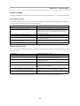
1
USER’S MANUAL
AXIS P7701 Video Decoder
AXIS P7701 User’s Manual
Notices
This manual is intended for administrators and users of the AXIS P7701
Video Decoder, and is applicable for firmware release 5.07 and later. It
includes instructions for using and managing the decoder on your
network. Previous experience of networking will be of use when using
this product. Some knowledge of UNIX or Linux-based systems may also
be beneficial, for developing shell scripts and applications. Later
versions of this document will be posted to the Axis Website, as
required. See also the product’s online help, available via the
Web-based interface.
Liability
Every care has been taken in the preparation of this manual. Please
inform your local Axis office of any inaccuracies or omissions. Axis
Communications AB cannot be held responsible for any technical or
typographical errors and reserves the right to make changes to the
product and manuals without prior notice. Axis Communications AB
makes no warranty of any kind with regard to the material contained
within this document, including, but not limited to, the implied
warranties of merchantability and fitness for a particular purpose. Axis
Communications AB shall not be liable nor responsible for incidental or
consequential damages in connection with the furnishing, performance
or use of this material.
Intellectual Property Rights
Axis AB has intellectual property rights relating to technology
embodied in the product described in this document. In particular, and
without limitation, these intellectual property rights may include one or
more of the patents listed at http://www.axis.com/patent.htm and one
or more additional patents or pending patent applications in the US and
other countries.
This product contains licensed third-party software. See the menu item
“About” in the product’s user interface for more information.
This product contains source code copyright Apple Computer, Inc.,
under the terms of Apple Public Source License 2.0 (see
http://www.opensource.apple.com/apsl/).
The source code is available from:
http://developer.apple.com/darwin/projects/bonjour/
Equipment Modifications
This equipment must be installed and used in strict accordance with the
instructions given in the user documentation. This equipment contains
no user-serviceable components. Unauthorized equipment changes or
modifications will invalidate all applicable regulatory certifications and
approvals.
Trademark Acknowledgments
Apple, Boa, Bonjour, Ethernet, Internet Explorer, Linux, Microsoft,
Mozilla, Netscape Navigator, OS/2, Real, QuickTime, UNIX, Windows,
WWW are registered trademarks of the respective holders. Java and all
Java-based trademarks and logos are trademarks or registered
trademarks of Sun Microsystems, Inc. in the United States and other
countries. Axis Communications AB is independent of Sun Microsystems
Inc.
UPnPTM is a certification mark of the UPnPTM Implementers Corporation.
Support
Should you require any technical assistance, please contact your Axis
reseller. If your questions cannot be answered immediately, your
reseller will forward your queries through the appropriate channels to
ensure a rapid response. If you are connected to the Internet, you can:
• download user documentation and firmware updates
• find answers to resolved problems in the FAQ database. Search by
product, category, or phrases
• report problems to Axis support by logging in to your private support
area
• visit Axis Support at www.axis.com/techsup
AXIS P7701 User’s Manual
Rev. 1.2
Copyright© Axis Communications AB, 2009 - 2010
June 2010 Part no. 39694
AXIS P7701 - Table of contents
Contents
AXIS P7701 Video Decoder . . . . . . . . . . . . . . . . . . . . . . . . . . . . . . . . . . . . . . . . . . . . . . . . . . . . . . . . . . . . . . . . . . . . . . . . . . 4
Key features . . . . . . . . . . . . . . . . . . . . . . . . . . . . . . . . . . . . . . . . . . . . . . . . . . . . . . . . . . . . . . . . . . . . . . . . . . . . . . 4
Hardware overview . . . . . . . . . . . . . . . . . . . . . . . . . . . . . . . . . . . . . . . . . . . . . . . . . . . . . . . . . . . . . . . . . . . . . . . . . . . . . . . . 5
Unit connectors . . . . . . . . . . . . . . . . . . . . . . . . . . . . . . . . . . . . . . . . . . . . . . . . . . . . . . . . . . . . . . . . . . . . . . . . . . . 6
LED indicators . . . . . . . . . . . . . . . . . . . . . . . . . . . . . . . . . . . . . . . . . . . . . . . . . . . . . . . . . . . . . . . . . . . . . . . . . . . . . 7
Accessing the Video Decoder . . . . . . . . . . . . . . . . . . . . . . . . . . . . . . . . . . . . . . . . . . . . . . . . . . . . . . . . . . . . . . . . . . . . . . . . 8
Access from a browser . . . . . . . . . . . . . . . . . . . . . . . . . . . . . . . . . . . . . . . . . . . . . . . . . . . . . . . . . . . . . . . . . . . . . . 8
Setting the root password . . . . . . . . . . . . . . . . . . . . . . . . . . . . . . . . . . . . . . . . . . . . . . . . . . . . . . . . . . . . . . . . . . . . . . . . . . 9
Access from the internet . . . . . . . . . . . . . . . . . . . . . . . . . . . . . . . . . . . . . . . . . . . . . . . . . . . . . . . . . . . . . . . . . . . . 9
Video Sources . . . . . . . . . . . . . . . . . . . . . . . . . . . . . . . . . . . . . . . . . . . . . . . . . . . . . . . . . . . . . . . . . . . . . . . . . . . . . . . . . . . . 10
Adding a video source . . . . . . . . . . . . . . . . . . . . . . . . . . . . . . . . . . . . . . . . . . . . . . . . . . . . . . . . . . . . . . . . . . . . . 10
Status . . . . . . . . . . . . . . . . . . . . . . . . . . . . . . . . . . . . . . . . . . . . . . . . . . . . . . . . . . . . . . . . . . . . . . . . . . . . . . . . . . . . . . . . . . 13
Video & Audio . . . . . . . . . . . . . . . . . . . . . . . . . . . . . . . . . . . . . . . . . . . . . . . . . . . . . . . . . . . . . . . . . . . . . . . . . . . . . . . . . . . 14
General Setup . . . . . . . . . . . . . . . . . . . . . . . . . . . . . . . . . . . . . . . . . . . . . . . . . . . . . . . . . . . . . . . . . . . . . . . . . . . . 14
System Options . . . . . . . . . . . . . . . . . . . . . . . . . . . . . . . . . . . . . . . . . . . . . . . . . . . . . . . . . . . . . . . . . . . . . . . . . . . . . . . . . . 16
Security . . . . . . . . . . . . . . . . . . . . . . . . . . . . . . . . . . . . . . . . . . . . . . . . . . . . . . . . . . . . . . . . . . . . . . . . . . . . . . . . . 16
Date & Time . . . . . . . . . . . . . . . . . . . . . . . . . . . . . . . . . . . . . . . . . . . . . . . . . . . . . . . . . . . . . . . . . . . . . . . . . . . . . 16
Network . . . . . . . . . . . . . . . . . . . . . . . . . . . . . . . . . . . . . . . . . . . . . . . . . . . . . . . . . . . . . . . . . . . . . . . . . . . . . . . . . 17
COM Port . . . . . . . . . . . . . . . . . . . . . . . . . . . . . . . . . . . . . . . . . . . . . . . . . . . . . . . . . . . . . . . . . . . . . . . . . . . . . . . . 21
Maintenance . . . . . . . . . . . . . . . . . . . . . . . . . . . . . . . . . . . . . . . . . . . . . . . . . . . . . . . . . . . . . . . . . . . . . . . . . . . . . 21
Support . . . . . . . . . . . . . . . . . . . . . . . . . . . . . . . . . . . . . . . . . . . . . . . . . . . . . . . . . . . . . . . . . . . . . . . . . . . . . . . . . 21
About . . . . . . . . . . . . . . . . . . . . . . . . . . . . . . . . . . . . . . . . . . . . . . . . . . . . . . . . . . . . . . . . . . . . . . . . . . . . . . . . . . . 22
Sequence Mode . . . . . . . . . . . . . . . . . . . . . . . . . . . . . . . . . . . . . . . . . . . . . . . . . . . . . . . . . . . . . . . . . . . . . . . . . . . . . . . . . . 23
Auto sequence mode . . . . . . . . . . . . . . . . . . . . . . . . . . . . . . . . . . . . . . . . . . . . . . . . . . . . . . . . . . . . . . . . . . . . . . 23
Manual sequence mode . . . . . . . . . . . . . . . . . . . . . . . . . . . . . . . . . . . . . . . . . . . . . . . . . . . . . . . . . . . . . . . . . . . . 23
Alarms . . . . . . . . . . . . . . . . . . . . . . . . . . . . . . . . . . . . . . . . . . . . . . . . . . . . . . . . . . . . . . . . . . . . . . . . . . . . . . . . . . . . . . . . . . 24
Setting up alarms . . . . . . . . . . . . . . . . . . . . . . . . . . . . . . . . . . . . . . . . . . . . . . . . . . . . . . . . . . . . . . . . . . . . . . . . . 24
Notification syntax . . . . . . . . . . . . . . . . . . . . . . . . . . . . . . . . . . . . . . . . . . . . . . . . . . . . . . . . . . . . . . . . . . . . . . . . 25
Resetting to Factory Default Settings . . . . . . . . . . . . . . . . . . . . . . . . . . . . . . . . . . . . . . . . . . . . . . . . . . . . . . . . . . . . . . . . 26
Troubleshooting . . . . . . . . . . . . . . . . . . . . . . . . . . . . . . . . . . . . . . . . . . . . . . . . . . . . . . . . . . . . . . . . . . . . . . . . . . . . . . . . . . 27
Checking the Firmware . . . . . . . . . . . . . . . . . . . . . . . . . . . . . . . . . . . . . . . . . . . . . . . . . . . . . . . . . . . . . . . . . . . . 27
Upgrading the Firmware . . . . . . . . . . . . . . . . . . . . . . . . . . . . . . . . . . . . . . . . . . . . . . . . . . . . . . . . . . . . . . . . . . . 27
Technical Specifications for AXIS P7701 . . . . . . . . . . . . . . . . . . . . . . . . . . . . . . . . . . . . . . . . . . . . . . . . . . . . . . . . . . . . . . 29
General performance considerations . . . . . . . . . . . . . . . . . . . . . . . . . . . . . . . . . . . . . . . . . . . . . . . . . . . . . . . . . 30
Glossary of Terms . . . . . . . . . . . . . . . . . . . . . . . . . . . . . . . . . . . . . . . . . . . . . . . . . . . . . . . . . . . . . . . . . . . . . . . . . . . . . . . . . 31
Index . . . . . . . . . . . . . . . . . . . . . . . . . . . . . . . . . . . . . . . . . . . . . . . . . . . . . . . . . . . . . . . . . . . . . . . . . . . . . . . . . . . . . . . . . . . 37
3
AXIS P7701 - AXIS P7701 Video Decoder
AXIS P7701 Video Decoder
AXIS P7701 Video Decoder provides a simple monitoring solution by enabling analog or digital monitors to connect to and
display live video from Axis network cameras and video encoders. AXIS P7701 is ideal for use with a public view monitor, and
in large and small surveillance systems.
AXIS P7701 can decode full frame rate video streams in H.264 and MPEG-4 in all resolutions up to D1 (720x480 pixels in
NTSC, 720x576 in PAL). Motion JPEG can be decoded in all resolutions up to 720p (1280x720).
AXIS P7701 can display video in resolutions up to 1280x720 pixels with its DVI output. The DVI interface is compatible with
monitors with a digital or analog DVI input, and with VGA and HDMI monitors with the use of appropriate adaptors. On its
composite video output, AXIS P7701 can display video up to D1 resolution. The audio out interface of AXIS P7701 supports the
output of audio decoded from the AAC, G.726 or G.711 input formats.
Through an RS-422/RS-485 serial port, AXIS P7701 allows serial commands to be sent to legacy equipment used in a
surveillance system.
An unlimited number of video sources can be shown in sequence. With auto-connect on alarm, AXIS P7701 can automatically
display alarm-triggered video.
The decoder can be powered using Power over Ethernet (PoE), which simplifies installation. An external power supply can also
be used.
In situations where only live video display is required—such as with a public view monitor at a store entrance, AXIS P7701
offers a more cost-effective solution than using a PC for connecting a monitor. AXIS P7701 can also complement a video
management system by helping to offload the main server from decoding digital streams simply for display purposes.
Key features
•
•
•
•
•
•
•
Full frame rate decoding of H.264, MPEG-4 and Motion JPEG
AXIS P7701 can decode H.264 and MPEG-4 at 30/25 (NTSC/PAL) fps in all resolutions up to D1 (720x480 pixels in
NTSC, 720x576 pixels in PAL). It can decode Motion JPEG in all resolutions up to 720p (1280x720 pixels).
High-quality digital video using DVI interface
Video can be digitally output in resolutions up to 1280 x 720 using the DVI interface. By using adapters, monitors with
either VGA or HDMI can be connected to AXIS P7701.
Analog output using composite video
Composite video can be output at up to D1 (720x480 pixels in NTSC, 720x576 pixels in PAL) resolution via an RCA
connector.
Sequence mode for multiple video sources
Multiple video sources can be displayed in sequence, either manually or automatically. Video sources can also be auto
connected when receiving an alarm.
High-quality audio
AXIS P7701 can decode audio in AAC, G.726 or G.711 formats and output high quality analog audio.
Serial port communication
Commands can be sent to surveillance equipment using the RS-422/485 serial port.
Advanced security and network management
AXIS P7701 offers the highest degree of security, including user password, IP address filtering and reception of HTTPS
encrypted video streams. AXIS P7701 has support for IP protocol version 6 in addition to the standard IPv4. IPv6 is a
requirement in many large installations.
4
AXIS P7701 - Hardware overview
Hardware overview
Top view
Mounting holes
Rear view
DVI-I connector
DVI OUT
OUT
P WR
S TAT
Network connector (PoE)
PoE
P OWE R
V IDE O
NE T
-
LED indicators for
power, status,
network and video
+
Power adapter connector
Audio, Video and I/O side view
Control button side view
RS-422/RS-485 connector
RS-485/422
I/O
AUDIO OUT
RX/TX
Audio out
TX
1 2 3 4
4-pin I/O terminal
VIDEO OUT
Control button
Video out
Dimensions
HxWxD = 33 x 99 x 118mm (1.3" x 3.9" x 4.7")
Weight AXIS P7701 = 318g (0.7 lb) power supply excl.
5
AXIS P7701 - Hardware overview
Unit connectors
Network connector - RJ-45 Ethernet connector. Supports Power over Ethernet (PoE). Using shielded cables is recommended.
Power connector - 2-pin terminal block used for power input to the video decoder with the supplied power
adapter or an external power supply 8-20V DC, max. 8.3 W.
1
Function
Pin number
Description
GND
1
Ground
DC Power
2
Power input 8-20V DC, max 8.3W
2
Note:
Do not connect a power supply if the video decoder is connected to PoE.
Audio out - Audio output that can be connected to a public address (PA) system or an active speaker with a built-in
amplifier. A pair of headphones can also be attached. A stereo connector must be used for the audio out.
DVI-I connector - The DVI-I connector has both analog and digital signals present simultaneously, so the DVI connector can
be used to connect to a monitor with either digital or analog input.
For digital input, the DVI-I connector can also be used to connect the AXIS P7701 to a monitor with a DVI input, or to a
monitor with a HDMI connector with the addition of a DVI-to-HDMI adapter.
The DVI connector can also be used with a DVI-to-VGA adapter to connect the AXIS P7701 to a monitor with a VGA analog
input.
RCA connector - Standard phono-type connector for composite video in PAL or NTSC. Allows direct connection of an analog
TV device.
Note:
If you connect the AXIS P7701 to a monitor using the RCA connector, you cannot use the DVI-I connector at the same time to connect to a second monitor.
I/O terminal connector - Used in applications for e.g. motion detection, event triggering, time lapse
recording and alarm notifications. It provides the interface to:
•
1 digital input - For a video select button
•
Auxiliary power and GND
1
Function
Pin
Notes
GND
1
Ground
3.3V DC Power
2
Can be used to power auxiliary equipment.
Note: This pin can only be used as power out.
Digital Input
3
Input for video select button.
Unused
4
Unused
2
3
4
Specifications
Max. load = 250mA
Note:
The video switch is not part of the AXIS P7701, and there is currently no optional video switch available from Axis.
However, it is possible for you to easily connect your own switch. See the connection diagram below..
6
AXIS P7701 - Hardware overview
The following connection diagram gives an example of how to connect an auxiliary device to the AXIS P7701.
1
AXIS P7701
3.3V max 250mA
Switch
Push to trigger video select
2
3 video input
4 Unused
RS-422/RS-485 connector - Two 2-pin terminal blocks for RS-485/422 serial interface used to control auxiliary equipment,
e.g. PTZ devices.
The RS-485/422 serial port can be configured to support:
•
•
•
•
RS-485/422
Two-wire RS-485 half duplex
Four-wire RS-485 full duplex
Two-wire RS422 simplex
Four-wire RS422 full duplex point to point communication
Function
Pin
Notes
RS-485/422 RX/TX A
1
RS-485/422 RX/TX B
2
(RX) For full duplex RS-485/422
(RX/TX) For half duplex RS-485
RS-485/422 TX A
3
RS-485/422 TX B
4
(TX) For full duplex RS-485/422
LED indicators
LED
Color
Indication
Video
Green
Encoder/Camera is connected.
Amber
Steady when connecting to an encoder/camera.
Red
No encoder/camera is connected.
Green
Steady for connection to a 100 Mbit/s network. Flashes for network activity.
Amber
Steady for connection to 10 Mbit/s network. Flashes for network activity.
Unlit
No network connection.
Green
Steady green for normal operation.
Amber
Steady during startup, during reset to factory default or when restoring settings.
Red
Slow flash for failed upgrade.
Green
Normal operation.
Amber
Flashes green/amber during firmware upgrade.
Network
Status
Power
7
RX/TX
1 2
TX
3 4
AXIS P7701 - Accessing the Video Decoder
Accessing the Video Decoder
To install this AXIS product, refer to the installation guide supplied with your product.
The video decoder can be used with most standard operating systems and browsers. The recommended browser is Microsoft
Internet Explorer with Windows, Safari with Macintosh and Firefox with other operating systems. See Technical Specifications
for AXIS P7701, on page 29.
Access from a browser
1. Start a browser (Internet Explorer, Firefox, Safari).
2. Enter the IP address or host name of the decoder in the Location/Address field of your browser.
To access the decoder from a Macintosh computer (Mac OSX), click on the Bonjour tab and select your AXIS product
from the drop-down list (the Bonjour tab is only available in Safari).
3. If this is the first time you are accessing the decoder, see Setting the root password, on page 9. Otherwise enter your
user name and password, set by the administrator.
4. The decoder’s Basic Setup page appears in your browser.
8
AXIS P7701 - Accessing the Video Decoder
Setting the root password
1. When accessing the decoder for the first time, the Configure Root Password
dialog appears.
Note:
Before you enter your password at this point, you can secure configuration of
the root password via HTTPS by creating a self-signed certificate. To do so, click
the Create self-signed certificate... button in the Create Certificate window.
To create an HTTPS connection,
click this button.
To configure the password directly
via an unencrypted connection, enter
the password here.
2. Enter a password and re-enter to confirm. Click OK. The Enter Network Password dialog appears.
3. Enter the password set in step 2, and click OK. If the password is lost, the decoder must be reset to the factory default
settings. See page 23.
Note:
The default administrator user name ‘root’ is permanent and cannot be deleted.
Access from the internet
Once connected, the decoder is accessible on your local network (LAN). To access the decoder from the Internet you must
configure your broadband router to allow incoming data traffic to the decoder. To do this, enable the NAT-traversal feature,
which will attempt to automatically configure the router to allow access to the decoder. This is enabled from System Options
> Network > TCP/IP Advanced.
For more information, please see NAT traversal (port mapping) for IPv4, on page 18. See also the AXIS Internet Dynamic DNS
Service at www.axiscam.net For Technical notes on this and other topics, visit the Axis Support web at www.axis.com/techsup
Notes:
•
•
•
HTTPS (Hypertext Transfer Protocol over SSL) is a protocol used to encrypt the traffic between web browsers and
servers. The HTTPS certificate controls the encrypted exchange of information.
The default administrator user root cannot be deleted.
If the password for root is lost or forgotten, the video decoder must be reset to the factory default settings. See page
23.
9
AXIS P7701 - Video Sources
Video Sources
This section describes how to add and manage video sources (encoders and cameras) in the AXIS P7701 Network Video
Decoder.
The Video Source List shows all of the sources currently added to the system. Various information about each source is shown,
including the source’s last known status.
A video source list can also be imported or exported.
Adding a video source
Click the Add... button to open the Add Video Source dialog.
When adding a new video source, ensure that it is correctly connected
and powered up before attempting configuration. The following settings
need to be made:
Name - Provide a unique name for the new video source.
Sequence mode - Select whether or not to include the video source in
auto and/or manual sequence mode. If Auto is selected, also enter a
Display time, to set how long the video source will be displayed for, before
switching to the next source in the list. Note that if neither sequence
mode is selected, the video source will only be displayed if the Connect to
button in the video source list is clicked, or if an alarm triggers display of
the source. See also page 14 for more information on sequence mode.
Video port number - Enter which video port on the video source should
be accessed. Some different valid values are, for cameras 1, for video
servers 1 to 4 or quad and for cameras supporting virtual image sources it is 1 to 8.
Http port - TCP/IP port to access http on video source.
Https port - TCP/IP port to access https on video source.
10
AXIS P7701 - Video Sources
Transport method - Select which protocol to use for transport:
•
•
•
•
•
•
•
Automatic
RTSP unicast
RTSP multicast
RTSP tunnel
HTTP
HTTP RTSP tunnel
HTTPS
Network settings
Address - Enter the IP address (or host name) of the video encoder or camera to add:
Example: 192.168.0.90
User Name and Password - If authentication is required by the video encoder or camera, enter the user name and password
to access it.
Notes:
•
•
Selecting a user with viewing rights only on the encoder or camera is recommended.
The video encoder’s or camera’s home pages can be opened in your browser by clicking the provided button.
Video & audio settings
Stream profile - Some video encoders and cameras support multiple stream profiles. If this is available, select the profile to
connect to. This value has no effect if the video encoder or camera only supports one stream profile.
Video type - Set the AXIS P7701 to automatically detect the video source format, or select the required format from the
drop-down list. Automatic attempts to detect formats in the following order:
•
•
•
•
•
•
•
•
•
•
•
•
H.264 RTP multicast
H.264 RTP unicast
H.264 RTP over RTSP
H.264 RTP over RTSP over HTTP
H.264 RTP over RTSP over HTTPS
MPEG-4 RTP multicast
MPEG-4 RTP unicast
MPEG-4 RTP over RTSP
MPEG-4 RTP over RTSP over HTTP
MPEG-4 RTP over RTSP over HTTPS
Motion JPEG
Motion JPEG over HTTPS
Selecting Automatic is recommended in most cases, but there are exceptions. For example, if Automatic is selected and the
video source supports MPEG-4 Multicast, then that format will automatically be selected. However, if the multicast data is
not correctly routed, the video stream from the encoder or camera will not reach the AXIS P7701. In this case, the format
should instead be set to MPEG-4 unicast.
As video sources are added to the AXIS P7701, they are stored in the decoder’s cache. This makes reconnecting to a source
much faster.
11
AXIS P7701 - Video Sources
Notes:
•
•
Performing certain actions will empty the unit’s cache and start a new round of autodetection.
When autodetect is used to connect to a new encoder or camera for the first time, the connection will take longer to
complete.
Resolution - This setting is valid for firmware 5.xx for all codecs. To use a resolution other than the source's default value,
select the custom radio button and enter the required resolution.
The resolutions available depend on the encoder or camera being used. Please see the encoder’s or camera’s online help for the
available resolutions.
Compression - This setting is valid for firmware 5.xx for all codecs. To use a compression other than the source's default
value, select the custom radio button and enter a compression value (0-100).
Audio - Select Audio to receive audio from the video source.
Preset position - If the video source has Pan/Tilt/Zoom capability, it is also possible to select a PTZ preset position view, by
entering the name of the preset here. To add new preset positions, please refer to the manual for the video source. When you
click OK, the PTZ device/camera should then move to the selected view.
12
AXIS P7701 - Status
Status
The Status page provides general status information, and also shows information on the video source currently connected to
the AXIS P7701 Video Decoder. A list of recent log messages are displayed at the bottom of the page. For more information
about log entries, please see the online help
.
13
AXIS P7701 - Video & Audio
Video & Audio
General Setup
This page provides settings for configuring the start up mode, alarm notification, video and audio output.
General
Connect at startup - When selected, the AXIS P7701 will automatically connect to the first video source in the video source
list at startup. When unselected, it will stay disconnected and wait for user input or alarms.
Automatic detection timeout - This defines how long time the decoder will wait for a video source to respond before it goes
to the next video source in the sequence.
Sequence mode - When set to Automatic, the AXIS P7701 automatically cycles through the video sources in the list on the
Video Sources page. In Manual mode, the next source is displayed when the video select button is pressed. See page 14 for
more information.
Video select button - Enables or disables the video select button.
Alarm
The AXIS P7701 can automatically switch to a video source that sends an alarm. See page 15 for more information.
Video Out
TV system - Select the TV system type to use. If you are using an analog monitor or television, most western European
countries use the PAL system, whereas the system in the United States is NTSC. For digital monitors and HDMI ready
televisions, the AXIS P7701 supports a resolution of up to 720p.
Consult the user documentation for your device to select a suitable resolution to set for TV system.
Video output - If you are using the RCA connector select Composite, otherwise select VGA and DVI if you are connecting
your device to the AXIS P7701 via the DVI-I connector.
14
AXIS P7701 - Video & Audio
Margin adjustment - As video monitors often use too much of the available screen area, some parts of the monitored scene
might not be visible. To correct this, the AXIS P7701 allows the margin to be adjusted on all 4 sides, so that the image is
forced more towards the center of the screen. A margin is added by default, and values (number of TV-lines) in the following
ranges are allowed:
•
•
PAL - Vertical: 0 till 575, Horizontal: 0 till 719. The sum of the vertical values cannot exceed 575.
The sum of the horizontal values cannot exceed 719.
NTSC- Vertical: 0 till 479, Horizontal: 0 till 719. The sum of the vertical values cannot exceed 479.
The sum of the horizontal values cannot exceed 719.
Audio out
Volume (0-100) - Set the level of the audio output on the AXIS P7701. The default value is 50. For more information see the
online help
15
AXIS P7701 - System Options
System Options
Security
Change password
Enter a password for the administrator or root user, and then re-enter it to confirm the spelling. Click OK. The password has
now been changed.
IP Address Filter
Enable IP Address Filtering to allow or deny access to the video decoder. Once enabled, the IP addresses in the list are allowed
or denied access according to the choice made in the drop-down list Allow/Deny the following IP addresses.
The administrator can add up to 256 IP address entries to the list (a single entry can contain multiple IP addresses).
HTTPS
The video decoder supports encrypted browsing using HTTPS.
A self-signed certificate can be used until a Certificate Authority-issued certificate has been obtained. Click the Create
self-signed Certificate button to install a self-signed certificate. Although self-signed certificates are free and offer some
protection, true security is only implemented after the installation of a signed certificate issued by a certificate authority.
A signed certificate can be obtained from an issuing Certificate Authority by clicking the Create Certificate Request button.
When the signed certificate is returned, click the Install signed certificate button to import the certificate. The properties of
any certificate request currently resident in the decoder or installed can also be viewed by clicking the Properties... button.
The HTTPS Connection Policy must also be set in the drop-down lists to enable HTTPS in the decoder.
For more information, please refer to the online help
.
802.1X
IEEE 802.1X is an IEEE standard for port-based Network Admission Control. It provides authentication to devices attached to a
network port (wired or wireless), establishing a point-to-point connection, or, if authentication fails, preventing access on
that port. 802.1X is based on EAP (Extensible Authentication Protocol).
In a 802.1X enabled network switch, clients equipped with the correct software can be authenticated and allowed or denied
network access at the Ethernet level.
Clients and servers in an 802.1X network may need to authenticate each other by some means. In the Axis implementation
this is done with the help of digital certificates provided by a Certification Authority. These are then validated by a third-party
entity, such as a RADIUS server, examples of which are Free Radius and Microsoft Internet Authentication Service.
To perform the authentication, the RADIUS server uses various EAP methods/protocols, of which there are many. The one used
in the Axis implementation is EAPOL using EAP-TLS (EAP-Transport Layer Security).
The Axis network video device presents its certificate to the network switch, which in turn forwards this to the RADIUS server.
The RADIUS server validates or rejects the certificate and responds to the switch, and sends its own certificate to the client for
validation. The switch then allows or denies network access accordingly, on a preconfigured port.
Date & Time
Current Server Time - Displays the current date and time (24h clock).
New Server Time - Select your time zone from the drop-down list. If you want the server clock to automatically adjust for
daylight savings time, select the Automatically adjust for daylight saving time changes option.
16
AXIS P7701 - System Options
From the Time Mode section, select the preferred method to use for setting the time:
•
•
•
Synchronize with computer time - sets the time from the clock on your computer.
Synchronize with NTP Server - the decoder will obtain the time from an NTP server continuously.
Set manually - this option allows you to manually set the time and date.
Note: If using a host name for the NTP server, a DNS server must be configured under TCP/IP settings.
See Network > Basic TCP/IP Settings below.
Network
Basic TCP/IP Settings
Your Axis video decoder supports both IP version 4 and IP version 6. Both versions may be enabled simultaneously, and at least
one version must always be enabled. When using IPv4, the IP address for the decoder can be set automatically via DHCP, or a
static IP address can be set manually. If IPv6 is enabled, the video decoders receive an IP address according to the
configuration in the network router. There are also options for setting up notification of changes in the IP address, and for
using the AXIS Internet Dynamic DNS Service. For more information on setting the IP address, please see the online help
.
Network Settings - Click the View button for an overview of the IP configuration of the video decoder.
IPv4 Address Configuration - Select the Enable IPv4 box option to enable IPv4.
Obtain IP address via DHCP - Dynamic Host Configuration Protocol (DHCP) is a protocol that lets network administrators
centrally manage and automate the assignment of IP addresses on a network. DHCP is enabled by default. Although a DHCP
server is mostly used to set an IP address dynamically, it is also possible to use it to set a static, known IP address for a
particular MAC address.
Note: DHCP should only be enabled if your DHCP server can update a DNS server, which then allows you to access the
video decoder by name (host name). If DHCP is enabled and you cannot access the unit, run AXIS IP Utility to search the network for connected Axis products or reset the video decoder to factory default settings and then perform the installation
again.
Use the following IP address - To use a static IP address for the video decoder, check the radio button and then make the
following settings:
•
•
•
IP address - Specify a unique IP address for your video decoder. (To check if the IP address you intend to use is available or not, click the Test button)
Subnet mask - Specify the mask for the subnet the video decoder is located on
Default router - Specify the IP address of the default router (gateway) used for connecting devices attached to different networks and network segments
IPv6 Address Configuration - Select the Enable IPv6 box option to enable IPv6. Other settings for IPv6 are configured in
the network router.
Services - Enable ARP/Ping setting of IP address - The IP address can be set using the ARP/Ping method, which associates
the unit's MAC address with an IP address. Check this box to enable the service. Leave disabled to prevent unintentional
resetting of the IP address.
Notes:
•
•
The ARP/Ping service is automatically disabled two minutes after the unit is started, or as soon as an IP address is set.
In order to reset the IP address, the decoder must be restarted to activate ARP/Ping for an additional two minutes.
Pinging the unit is still possible when this service is disabled.
AXIS Internet Dynamic DNS Service - Use the AXIS Internet Dynamic DNS service to assign a host name for easy access to
your video decoder (requires Internet access).
17
AXIS P7701 - System Options
Click System Options > Network > Basic > Settings... to register the decoder with the Axis Internet Dynamic DNS service, or
to modify the existing settings (requires access to the Internet). The domain name currently registered at the Axis Internet
Dynamic DNS service for your product can at any time be removed.
For more information, please refer to the online help
.
Advanced TCP/IP Settings
DNS Configuration - DNS (Domain Name Service) provides the translation of host names to IP addresses on your network.
Obtain DNS server address via DHCP - Automatically use the DNS server settings provided by the DHCP server. Click the View
button to see the current settings.
Use the following DNS server address - Enter the desired DNS server by specifying the following:
Domain name - Enter the domain(s) to search for the host name used by the video decoders. Multiple domains can be
separated by semicolons (;). The host name is always the first part of a Fully Qualified Domain Name, for example, myserver is
the host name in the Fully Qualified Domain Name myserver.mycompany.com where mycompany.com is the Domain name.
Primary and Secondary DNS servers - Enter the IP addresses of the primary, and secondary DNS servers.
Note: This is not mandatory with regard to secondary DNS servers.
NTP Configuration - Check the Obtain NTP server address via DHCP radio button to automatically look up and use the
NTP server settings as provided by DHCP. Click the View button to see the current settings.
Use the following NTP server address - To create manual settings, check this radio button and enter the host name or IP
address of the NTP server.
Host Name Configuration - The video decoders can be accessed using a host name, instead of an IP address. The host
name is usually the same as the assigned DNS Name.
For more information, please see Security, on page 16.
Link-Local IPv4 Address - This is enabled by default and assigns the video decoders an additional IP address for use with
UPnP™. The decoder can have both a Link-Local IP and a static/DHCP-supplied IP address at the same time - these will not
affect each other.
HTTP and HTTPS - The default HTTP/HTTPS port numbers (80 and 443 respectively) can be changed to any port within the
range 1024-65535. This is useful for simple security port mapping, for example.
NAT traversal (port mapping) for IPv4 - A broadband router allows devices on a private network (LAN) to share a single
connection to the Internet. This is done by forwarding network traffic from the private network to the “outside”, that is, the
Internet. Security on the private network (LAN) is increased since most broadband routers are pre-configured to stop attempts
to access the private network (LAN) from the public network/Internet.
18
AXIS P7701 - System Options
Use NAT traversal when your video decoders are located on an intranet (LAN) and you wish to make it available from the
other (WAN) side of a NAT router. With NAT traversal properly configured, all HTTP traffic to an external HTTP port in the NAT
router is forwarded to the decoder.
LAN (intranet)
WAN (internet)
Broadband
(NAT)
router
ISP
Notes:
• For NAT traversal to work, this must be supported by the broadband router.
• The broadband router has many different names: “NAT router”, “Network router“, Internet Gateway”, “Broadband
sharing device” or “Home firewall” but the essential purpose of the device is the same.
Enable/Disable - when enabled, the video decoders attempt to configure port mapping in a NAT router on your network, using
UPnP™. Note that UPnP™ must be enabled in the decoder (see System Options > Network > UPnP).
Use manually selected NAT router - select this option to manually select a NAT router and enter the IP address for the router
in the field provided.
If a router is not manually specified, the video decoders automatically search for NAT routers on your network. If more than
one router is found, the default router is selected.
Alternative HTTP port - select this option to manually define an external HTTP port. Enter the port number in the field
provided. If no port is entered here a port number is automatically selected when NAT traversal is enabled.
Notes:
• An alternative HTTP port can be used/be active even if NAT traversal is disabled. This is useful if your NAT router does
not support UPnP and you need to manually configure port forwarding in the NAT router.
• If you attempt to manually enter a port that is already in use, another available port is automatically selected.
• When the port is selected automatically it is displayed in this field. To change this enter a new port number and click
Save.
FTP - The FTP server running in the video decoders enables the upload of new firmware, and user applications. Check the box
to enable the service.
Proxy settings
Proxy settings allows you to set up an HTTP proxy server if, for example, you want the AXIS P7701 to be able to access
cameras outside of a firewall. Follow the steps below to set up an HTTP proxy server:
1.
2.
3.
4.
5.
Select enable to use the HTTP proxy server
Enter a descriptive name for the proxy server
Specify which port to use. The default port is 8080
Enter local network IP addresses with subnet mask
Enter the User name and Password for the proxy server
19
AXIS P7701 - System Options
SMTP (email)
Enter the host names (or IP addresses) and port numbers for your primary and secondary mail servers in the fields provided, to
enable the sending of notifications from the decoder to predefined addresses via SMTP.
If your mail server requires authentication, check the box for Use authentication to log in to this server and enter the
necessary information. See the online help
for more information.
SNMP
The Simple Network Management Protocol (SNMP) allows remote management of network devices. An SNMP community is
the group of devices and management station running SNMP. Community names are used to identify groups.
Depending on the level of security required, select the version of SNMP to use. The three levels of security are:
SNMP v1/v2 - Select either SNMP V1 that includes no security, or SNMP V2c that uses very simple security.
The community name can be specified as a password for read or read/write access to all supported SNMP objects. The
community is the group of network devices using SNMP. The default password for the Read Community is public and the
default password for the Write community is write.
Traps for SNMP v1/v2
Traps are used by the decoder to send messages to a management system for important events or status changes.
If Enable traps is selected, enter the IP address where the trap message is to be sent as well as the Trap community that
should receive the message.
There are four types of traps available for the video decoder.
•
•
•
•
Cold start
Warm start
Link up
Authentication failed
SNMP v3 - SNMP V3 - provides encryption and secure passwords. HTTPS must be enabled. To use traps with SNMP v3 an
SNMP v3 management application is required.
If the Enable SNMP v3 option is enabled, provide the Initial user password. Note that the initial password is activated only
when HTTPS is enabled and can only be set once.
If HTTPS is enabled, SNMP v1 and SNMP v2c should be disabled.
When SNMP configuration is ready, click Save to use the new settings or Reset to return to the default values.
UPnP™
The video decoder includes support for UPnP™. UPnP™ is enabled by default, and the video decoder then is automatically
detected by operating systems and clients that support this protocol.
Bonjour
The video decoder includes support for Bonjour. When enabled, the decoder is automatically detected by operating systems
and clients that support this.
Ports & Devices
This page allows configuration of the COM port. For more information please see the online help
20
.
AXIS P7701 - System Options
COM Port
The RS-422/RS-485 serial connector allows you to connect legacy and auxiliary equipment to the AXIS P7701. Once
connected, an encoder or camera can be configured to receive data such as alarms and messages from these devices.
Serial port settings - Select the appropriate settings for connecting your auxiliary device to the AXIS P7701. Consult device’s
user documentation for the appropriate settings.
Use the Mode setting to either manually Off, or automatically Auto, send data from your device to an encoder or camera.
The auxiliary device can be connected to the AXIS P7701 using either the RS-485 or RS-422 serial interface. If RS-485 is
selected, the data direction can be set to either Full or Half duplex.
For more information please see the online help
.
Maintenance
Restart - •The decoder is restarted without changing any settings.
Restore - •The unit is restarted and most current settings are reset to factory default values. The settings that do not reset
are:
• the boot protocol (DHCP or static)
• the static IP address
• the default router
• the subnet mask
• the product interface language
• the system time
Default - The default button should be used with caution. Pressing this returns the decoder's settings to the factory default
values (including the IP address).
Upgrade Server - See Upgrading the Firmware, on page 27.
Support
The Support Overview page provides valuable information on troubleshooting and contact information, should you require
technical assistance.
The System Overview page provides an overview of the decoder’s status and settings. Information that can be found here
includes the decoder’s firmware version, IP address, video sources, security and recent log items. Many of the captions are also
links to other pages where you can make adjustments to the decoder’s settings.
Logs & Reports
When contacting Axis support, please be sure to provide a valid
Server Report with your query. The Access Log is automatically
included in the server report.
Information - the Server Report and Parameter List may prove
useful when troubleshooting a problem or when contacting the Axis
support web.
•
•
System Log - Provides information about system events.
Access Log - By default, the Access Log lists all failed attempts to access the decoder but can be configured to list
all connections to the decoder, whether successful or not. Go to Support > Logs & Reports > Configuration and
select the desired level of information from the list. See Configuration - From the drop-down lists, select the level
of information to be added to the System Log and Access Log files and the permitted size of the log files., on page 22
21
AXIS P7701 - System Options
•
•
for more information.
The Access Log is useful for various purposes such as tracking all access to the decoder, simple web attraction
tracking, system analysis and troubleshooting.
Server Report - Provides information about the server status and should always be included when requesting
support.
Parameter List - Shows the unit's parameters and their current settings.
Configuration - From the drop-down lists, select the level of information to be added to the System Log and Access Log files
and the permitted size of the log files.
The default information level for the Access Log is set to Critical & Warnings, i.e. failed connections. However, in an error
situation and when requesting support, set it to the highest information level - Critical & Warnings & Info.
For the Log Level for Email, select from the drop-down list the level of information to send as email and enter the destination
email address.
Advanced
Scripting is an advanced function that enables you to customize and use scripts. This function is a very powerful tool.
Note: Improper use may cause unexpected behavior or even cause loss of contact with the unit. If a script does cause
problems, reset the unit to its factory default settings. A backup file may be of use to return the unit to its latest
configuration.
Axis recommends that you do not use this function unless you understand the consequences. Note that Axis support does
not provide assistance for problems with customized scripts.
For more information, please visit the Developer pages at www.axis.com/developer
Plain Config - this function is for the advanced user with experience of Axis video decoder configuration. All parameters can
be set and modified from this page. Help is available from the standard help pages.
About
Here you can find basic information about your video decoder. You can also view third party software licenses.
22
AXIS P7701 - Sequence Mode
Sequence Mode
The AXIS P7701 displays the video from the connected sources in 2 different sequence modes - auto mode and manual mode.
Auto sequence mode
In this mode, the video sources in the list on the Video Sources page are automatically cycled through, one by one. Auto mode
can be paused and resumed by pressing the Video Select button.
Action/event
Result in auto sequence mode
Connection established
Video source displayed.
Connection to currently playing source is lost.
Screen goes blank and, depending on the remaining display time, the
decoder either tries to reconnect or goes to the next source. The source
cache is cleared, resulting in a new autodetection. See also Adding a
video source, on page 10.
Video select button is pressed during display.
Automatic cycling is paused.
Video select button is pressed during pause.
Automatic cycling is resumed directly at the next source.
Parameters are changed.
The connection cache is cleared and all sources are autodetected again
upon the next connection.
User presses Connect to button in web interface to connect
to a video source not included in the auto mode list.
The decoder connects to that source. After the display time has
elapsed, the next source in the auto list is selected.
Alarm received from video encoder or camera.
Alarm is ignored.
Manual sequence mode
When in manual mode, the AXIS P7701 displays a single video source and only skips to the next source when the video select
button is pressed.
Action/event
Result in manual sequence mode
Connection established
Video source displayed.
Connection to currently playing source is lost.
The screen goes blank and the decoder attempts to reconnect. The
source cache is cleared, resulting in a new autodetection.
Video select button is pressed during display.
Decoder cycles to next source. If the next source is not already cached,
autodetection will occur.
Video select button is pressed during autodetect of next
source.
Autodetect is aborted on that source and the decoder attempts to go
to the next source.
Parameters are changed.
The connection cache is cleared and all sources are autodetected
again, upon the next connection.
User uses Connect to button in web interface to connect to
a video source not included in the manual mode list.
The decoder connects to that source. When the video select button is
pressed, the next source in the manual mode list is selected.
Alarm notification received from video encoder or camera.
Decoder switches to display from the encoder or camera that sent the
alarm.
Note: Keeping the video select button pressed for more than 2 seconds will disconnect the AXIS P7701.
23
AXIS P7701 - Alarms
Alarms
Many Axis video encoders and network cameras can send notification messages whenever certain types of events occur. These
messages can be received by the AXIS P7701 and used as alarms. The incoming alarm causes the AXIS P7701 to switch to the
video source in the alarm message. The AXIS P7701 automatically switches to the video source in the alarm message.
The notification messages sent by video encoders or cameras are the result of events occurring in those devices. These events
may be triggered by an incoming signal on an input on the encoder or camera, or they may be the result of detected motion in
the scene monitored by the encoder or camera.
External alarm
device
Alarm
Alarm notification
AXIS P7701
Motion detection
alarm
TCP/IP
Network
Work station
To allow alarms to be received by the AXIS P7701, the Sequence mode must be set to Manual, and Receive alarms must be set
to Yes. Both settings are found on the General settings page. When enabled, the AXIS P7701 automatically switches to the
video source specified in the alarm message.
Note: The ability to send TCP and HTTP notification messages depends on the Axis video encoder or camera being used.
Setting up alarms
For the AXIS P7701 to respond correctly to alarms, the following steps need to be taken:
1. To configure the AXIS P7701, add the video encoder or camera to the list of video sources. Refer to Adding a video
source, on page 10 for instructions.
2. To configure the video encoder or network camera, add the AXIS P7701 as a TCP or HTTP Event Server. These screen
shots show examples of both types of servers. Refer to the documentation of the video encoder or camera for
instructions on how to set up an Event Server.
24
AXIS P7701 - Alarms
Notes:
•
•
The URL for an HTTP event server should be set to: http://<IP address>/axis-cgi/admin/alarm.cgi
The TCP alarm port on the AXIS P7701 is configured on the Network Settings page.
3. Configure the Event Type to send a notification message to the event server (i.e. the AXIS P7701).
Notification syntax
The notification message is formatted differently for TCP and HTTP.
TCP notification syntax
Enter the notification message in the Message field, in the format:
sourcename=<name from list>&textmessage=<my message>
For example:
sourcename=DoorCam1&textmessage=Door is open
The message is sent to the TCP port (default 2048) on the AXIS P7701.
HTTP notification syntax
Enter the notification message in the Custom parameters field, in the format:
sourcename=<name from list>&textmessage=<my message>
For example:
sourcename=DoorCam1&textmessage=Door%20is%20open
The message is sent to the HTTP port (default 80) on the AXIS P7701.
Note: All non-alphanumerical characters included in an HTTP notification message must be URL-encoded.
For example, a blank space must be written as %20, as in Door%20is%20open.
For more information, please see the online help. For more information concerning the video encoder or camera, see that
product’s documentation and online help.
25
AXIS P7701 - Resetting to Factory Default Settings
Resetting to Factory Default Settings
To reset the AXIS P7701 to its original factory default settings, go to the System Options > Maintenance web page (as
described in Maintenance, on page 21) or use the Control button (see page 5) as described below:
Using the Control Button
To reset the decoder to the factory default settings using the Control Button:
1.
2.
3.
4.
5.
Disconnect the power cable or if using PoE, disconnect the network cable.
Press and hold the Control button while reconnecting power.
Keep the Control button pressed until the Status indicator displays amber (this may take up to 15 seconds).
Release the Control button.
When the Status indicator changes to green (which may take up to 1 minute), the process is complete and the
decoder has been reset. The unit now has the default IP address 192.168.0.90
Note: For other methods of setting the IP address, please refer to the product’s Installation Guide that accompanies the
product, or download a copy from www.axis.com.
26
AXIS P7701 - Troubleshooting
Troubleshooting
Checking the Firmware
Firmware is software that determines the functionality of the video decoder. One of your first actions when troubleshooting a
problem should be to check the current firmware version. The latest version may contain a correction that fixes your particular
problem. The current firmware version in your decoder is displayed on the page About.
Upgrading the Firmware
When you upgrade your decoder with the latest firmware from the Axis Web site, your decoder receives the latest
functionality available. Always read the upgrade instructions and release notes available with each new release, before
updating the firmware.
Note:
Preconfigured and customized settings are saved when the firmware is upgraded (providing the features are available
in the new firmware) although this is not guaranteed by Axis Communications. Always read the instructions and
release notes available with each new release, before upgrading the firmware.
1. Save the firmware file to your computer. The latest
version of the firmware is available free of charge
from the Axis website at www.axis.com/techsup
2. Go to System Options > Maintenance in the
decoder’s web pages.
3. In the Upgrade Server section, browse to the desired
firmware file on your computer. Click Upgrade.
Notes:
•
•
•
After starting the upgrade process, always wait at
least 5-10 minutes before restarting the decoder, even if you suspect the upgrade has failed.
Your dealer reserves the right to charge for any repair attributable to faulty upgrading by the user.
The AXIS Camera Management software tool can be used for multiple upgrades. Please see the Axis website at
www.axis.com for more information.
Emergency Recovery Procedure
If power or the network connection to the decoder is lost during the upgrade, the process fails and the unit becomes
unresponsive. A flashing red Status LED indicates a failed upgrade.To recover the unit, follow the steps below. The serial
number is found on the label attached to the bottom of the decoder.
1. UNIX/Linux - From the command line, type the following:
arp -s <IP address of decoder> <serial number> temp
ping -s 408 <IP address of decoder>
2.
3.
4.
5.
Windows - From a command/DOS prompt, type the following:
arp -s <IP address of decoder> <serial number>
ping -l 408 -t <IP address of decoder>
If the unit does not reply within a few seconds, restart it and wait for a reply. Press CTRL+C to stop Ping.
Open a browser and type in the decoder’s IP address. In the page that appears, use the Browse button to select the
upgrade file to use, for example, axisp3343.bin. Then click the Load button to restart the upgrade process.
After the upgrade is complete (1-10 minutes), the unit automatically restarts and shows a steady green on the Power
and Status LEDs and flashing green or amber on the Network LED.
Reinstall the decoder, referring to the installation guide.
If the emergency recovery procedure does not get the decoder up and running again, please contact Axis support at
www.axis.com/techsup/
27
AXIS P7701 - Troubleshooting
Axis Support
If you contact Axis support, please help us to help you solve your problems by providing the server report, the log file and a
detailed description of the problem.
Server Report - go to System Options > Support > Support Overview. The server report contains important information
about the server and its software, as well as a list of the current parameters.
The Log file is available from System Options > Support > Logs & Reports. The Log file records events in the unit since the
last system restart and can be a useful diagnostic tool when troubleshooting.
Symptoms, Possible Causes, and Remedial Action
Problems setting the IP address
Try installation again. The IP address must be set within two minutes after power is
applied to the decoder. Ensure the Ping length is set to 408. See Installation Guide.
The decoder is located on a different
If the IP address intended for the decoder and the IP address of your computer are
subnet
located on different subnets, you will not be able to set the IP address. Contact your
network administrator to obtain an appropriate IP address.
The IP address is being used by another Disconnect the decoder from the network. Run the Ping command. (In a Comdevice
mand/DOS window, type ping and the IP address of the unit).
If you receive: Reply from <IP address>: bytes = 32; time = 10 ms..... - this means
that the IP address may already be in use by another device on your network. You
must obtain a new IP address and reinstall the unit.
If you see: Request timed out - this means that the IP address is available for use
with your decoder. In this case, check all cabling and reinstall the unit.
Possible IP address conflict with
The static IP address in the decoder is used before the DHCP server sets a a dynamic
another device on the same subnet
address. This means that if the same default static IP address is used by another
device, there may be problems accessing the decoder. To avoid this, set the static IP
address to 0.0.0.0.
When using ARP/Ping
The decoder cannot be accessed from a browser
The IP address has been changed by
DHCP
Other networking problems
If the decoder and client are on the same network, Run AXIS IP Utility to locate the
decoder. Identify the decoder using its model or serial number. Alternatively:
1) Move the decoder to an isolated network or to one with no DHCP or BOOTP server.
Set the IP address again, using the AXIS IP Utility (see the Installation Guide) or the
ARP/Ping commands.
2) Access the unit and disable DHCP in the TCP/IP settings. Return the unit to the
main network. The unit now has a fixed IP address that will not change.
3) As an alternative to 2), if dynamic IP address via DHCP or BOOTP is required, select
the required service and then configure IP address change notification from the network settings. Return the unit to the main network. The unit now has a dynamic IP
address, but will notify you if the address changes.
Test the network cable by connecting it to another network device, then Ping that
device from your workstation. See instructions above.
The decoder is accessible locally, but not externally
Broadband router configuration
Firewall protection
Default routers required
To configure your broadband router to allow incoming data traffic to the decoder,
enable the NAT-traversal feature which will attempt to automatically configure the
router to allow access to the decoder.
This is enabled from System Options > Network > TCP/IP Advanced.
Check the Internet firewall with your system administrator.
Check if you need to configure the default router settings.
The Power indicator is not constantly lit
Faulty power supply
Check that you are using the same indoor power supply that came with the product.
The Network indicator LEDs are flashing red rapidly
Hardware failure
Contact your Axis dealer.
For further assistance, please contact your reseller or see the support pages on the Axis website at www.axis.com/techsup
28
Technical Specifications for AXIS P7701
Technical Specifications for AXIS P7701
Function/group
Item
Decoder
Models
Video
Video compression
• H.264
• MPEG-4 Part 2
• Motion JPEG
Resolutions
• H.264 and MPEG-4 Part 2; All resolutions up to D1 (720x480 in NTSC,
720x576 in PAL)
• Motion JPEG; All resolutions up to 720p (1280x720) (720x480 pixels in
NTSC, 720x576 pixels in PAL)
Audio
System
Integration
AXIS P7701 Video Decoder
Frame rate H.264
30/25 (NTSC/PAL) fps in up to D1 resolution
Frame rate MPEG-4
part 2
30/25 (NTSC/PAL) fps in up to D1 resolution
Frame rate
Motion JPEG
Up to 15 (NTSC/PAL) fps in 720p resolution
Video streaming
• One stream H.264/Motion JPEG/MPEG-4 part 2 decoding
Image settings
• NTSC/PAL
• VGA (60/75Hz)
• S-VGA (60/75Hz)
• 1280 x 720 (16:9) via DVI-I connector
Serial Connection
Forwarding of serial commands
Audio streaming
One way
Audio compression
Network
Specification
• AAC-LC 8 kHz 32 kbit/s, 16 kHz 64 kbit/s
• G.711 PCM 8 kHz 64 kbit/s
• G.726 ADPCM 8 kHz 32 or 24 kbit/s
Audio input/output
Line output
Security
Password protection, IP address filtering, HTTPS encryption, IEEE 802.1X
network access control, digest authentication, user access log
Supported protocols
IPv4/v6, HTTP, HTTPS, FTP, SMTP, Bonjour, UPnP, SNMPv1/v2c/v3(MIB-II),
DNS, DynDNS, NTP, RTSP, RTP, TCP, UDP, IGMP, RTCP, ICMP, DHCP, ARP,
SSL/TLS
Application
Programming
Interface
Open API for software integration, including VAPIX® from Axis
Communications available at www.axis.com
Alarm triggers
Ability to receive external alarms according to specified VAPIX API
Alarm events
Notification via email
29
Technical Specifications for AXIS P7701
Function/group
Item
Specification
General
Casing
• Metal casing. Standalone or wall mount
Processors, memory
• TI TMS320DM6443, 128MB RAM, 128MB Flash
Power
Connectors
8-20 V DC, max. 8.3 W or Power over Ethernet IEEE 802.3af Class 3
• RCA composite video output
• DVI-I (digital and analog) output
• RJ-45 10BASE-T/100BASE-TX PoE
• DC terminal block: 8-20 V DC max. 8.3 W
• I/O terminal block: input for a video select button, and a 3.3V @ 250mA
power output
• RS-485/ RS-422 terminal block
• 3.5 mm audio line/headphones output, mono
Operating conditions • 0-50 °C (32-122 °F) Humidity 20-80% RH (non-condensing)
Approvals
Dimensions (HxWxD)
Weight
• EN 55022 Class B, EN 61000-3-2, EN 61000-3-3, EN 55024, FCC Part 15
Subpart B Class B, ICES-003, VCCI Class B, AS/NZS CISPR 22, EN 60950-1,
KCC
33 x 99 x 118 mm
• 318 g (0.7lb)
General performance considerations
When setting up your system, it is important to consider how various settings and situations will affect performance. Some
factors affect the amount of bandwidth (the bit rate) required, others can affect the frame rate, and some affect both. If the
load on the CPU reaches its maximum, this will also affect the frame rate. Also, high image resolutions and lower compression
levels result in larger images.
30
Glossary of Terms
Glossary of Terms
transmission methods where two or more signals share the
same carrier. In more popular terminology, broadband is taken
to mean high-speed data transmission.
720p - 720p refers to 720 lines of progressive video (720 lines
per frame). Higher resolution than standard DVD, which is 480i
or 480p. Usually refers to 1280x720 resolution in 1.78 aspect
ratio.
CCD (Charged Coupled Device) - This light-sensitive image
device used in many digital cameras is a large integrated circuit
that contains hundreds of thousands of photo-sites (pixels)
that convert light energy into electronic signals. Its size is
measured diagonally and can be 1/4", 1/3", 1/2" or 2/3".
ActiveX - A standard that enables software components to
interact with one another in a networked environment,
regardless of the language(s) used to create them. web
browsers may come into contact with ActiveX controls, ActiveX
documents, and ActiveX scripts. ActiveX controls are often
downloaded and installed automatically as required.
CGI (Common Gateway Interface) - A specification for
communication between a web server and other (CGI)
programs. For example, a HTML page that contains a form
might use a CGI program to process the form data once it is
submitted.
Angle - The field of view, relative to a standard lens in a 35mm
still camera, expressed in degrees, e.g. 30°. For practical
purposes, this is the area that a lens can cover, where the angle
of view is determined by the focal length of the lens. A
wide-angle lens has a short focal length and covers a wider
angle of view than standard or telephoto lenses, which have
longer focal lengths.
CIF (Common Intermediate Format) - CIF refers to the analog
video resolutions 352x288 pixels (PAL) and 352x240 pixels
(NTSC). See also Resolution.
Client/Server - Client/server describes the relationship
between two computer programs in which one program, the
client, makes a service request from another program, the
server, which fulfils the request. Typically, multiple client
programs share the services of a common server program. A
web browser is a client program that requests services (the
sending of web pages or files) from a web server.
ARP (Address Resolution Protocol) - This protocol is used to
associate an IP address to a hardware MAC address. A request
is broadcast on the local network to discover the MAC address
for an IP address.
ARTPEC (Axis Real Time Picture Encoder) - This chip is used
for image compression, and image processing such as
conversion of raw image sensor data, color correction,
sharpening, noise filtering etc.
CMOS (Complementary Metal Oxide Semiconductor) - A
CMOS is a widely used type of semiconductor that uses both
negative and positive circuits. Since only one of the circuit
types is on at any given time, CMOS chips require less power
than chips using just one type of transistor. CMOS image
sensors also allow processing circuits to be included on the
same chip, an advantage not possible with CCD sensors, which
are also much more expensive to produce.
ASIC (Application Specific Integrated Circuit) - A circuit
designed for a specific application, as opposed to a general
purpose circuit, such as a microprocessor.
Aspect ratio - A ratio of width to height in images. A common
aspect ratio used for television screens and computer monitors
is 4:3. High-definition television (HDTV) uses an aspect ratio of
9:16.
Codec - In communications engineering, a codec is usually a
coder/decoder. Codecs are used in integrated circuits or chips
that convert e.g. analog video signals into a digital format for
transmission. The codec also converts received digital signals
back into analog format. A codec uses analog-to-digital
conversion and digital-to-analog conversion in the same chip.
Autoiris (DC-Iris) - This special type of iris is electrically
controlled by the camera, to automatically regulate the amount
of light allowed to enter.
Codec can also mean compression/decompression, in which
case it is generally taken to mean an algorithm or computer
program for reducing the size of large files and programs.
Bitmap - A bitmap is a data file representing a rectangular grid
of pixels. It defines a display space and color for each pixel (or
‘bit’) in the display space. This type of image is known as a
‘raster graphic.’ GIFs and JPEGs are examples of image file types
that contain bitmaps.
Compression - See Image compression.
Composite video - A type of video signal in which all
information—the red, blue, and green signals (and sometimes
audio signals as well)—are mixed together. This is the type of
signal used by analog televisions in the United States (see
NTSC).
Because a bitmap uses this fixed raster method, it cannot easily
be rescaled without losing definition. Conversely, a vector
graphic image uses geometrical shapes to represent the image,
and can thus be quickly rescaled.
DC-Iris (Autoiris) - This special type of iris is electrically
controlled by the camera, to automatically regulate the amount
of light allowed to enter.
Bit rate - The bit rate (in kbit/s or Mbit/s) is often referred to
as speed, but actually defines the number of bits/time unit and
not distance/time unit.
DHCP (Dynamic Host Configuration Protocol) - DHCP is a
protocol that lets network administrators automate and
centrally manage the assignment of Internet Protocol (IP)
addresses to network devices in a network.
Bonjour - Also known as zero-configuration networking,
Bonjour enables devices to automatically discover each other
on a network, without having to enter IP addresses or configure
DNS servers. Bonjour is a trademark of Apple Computer, Inc.
DHCP uses the concept of a ‘lease’ or amount of time that a
given IP address will be valid for a computer. The lease time can
Broadband - In network engineering terms, this describes
31
Glossary of Terms
vary, depending on how long a user is likely to require the
network connection at a particular location.
which a video stream is updated is measured in frames per
second (fps). A higher frame rate is advantageous when there is
movement in the video stream, as it maintains image quality
throughout.
DHCP also supports static addresses for e.g. computers running
web servers, which need a permanent IP address.
Gain - Gain is the amplification factor and the extent to which
an analog amplifier boosts the strength of a signal.
Amplification factors are usually expressed in terms of power.
The decibel (dB) is the most common way of quantifying the
gain of an amplifier.
DNS (Domain Name System) - DNS is used to locate and
translate Internet domain names into IP (Internet Protocol)
addresses. A domain name is a meaningful and
easy-to-remember name for an Internet address. For example
the domain name www.example.com is much easier to
remember than 192.0.34.166. The translation tables for domain
names are contained in Domain name servers.
Gateway - A gateway is a point in a network that acts as an
entry point to another network. In a corporate network for
example, a computer server acting as a gateway often also acts
as a proxy server and a firewall server. A gateway is often
associated with both a router, which knows where to direct a
given packet of data that arrives at the gateway, and a switch,
which furnishes the actual path in and out of the gateway for a
given packet.
D-1 - SMPTE digital VTR video standard. It has a resolution of
720 × 486 for NTSC systems and 720 × 576 for PAL systems.
Domain Server - Domains can also be used by organizations
who wish to centralize the management of their (Windows)
computers. Each user within a domain has an account that
usually allows them to log in to and use any computer in the
domain, although restrictions may also apply. The domain
server is the server that authenticates the users on the network.
GIF (Graphics Interchange Format) - GIF is one of the most
common file formats used for images in web pages. There are
two versions of the format, 87a and 89a. Version 89a supports
animations, i.e. a short sequence of images within a single GIF
file. A GIF89a can also be specified for interlaced presentation.
DVI - Digital Visual Interface, an interface standard that
specifies a connector and signaling methods used to transmit
video information in both analog and digital formats.
GOV (Group Of VOPs) - A group of VOPs is the basic unit of
an H.264 video stream. The GOV contains different types and
numbers of VOPs (I-VOPs, P-VOPs) as determined by the GOV
length and GOV structure. See also VOP.
Ethernet - Ethernet is the most widely installed local area
network technology. An Ethernet LAN typically uses special
grades of twisted pair wires. The most commonly installed
Ethernet systems are 10BASE-T and 100BASE-T10, which
provide transmission speeds up to 10 Mbps and 100 Mbps
respectively.
GOV length - The GOV length determines the number of
images (VOPs) in the GOV structure. See also GOV and VOP.
GOV structure - The GOV structure describes the composition
of an H.264 video stream, as regards the type of images (I-VOPs
or P-VOPs) included in the stream, and their internal order. See
also GOV and VOP.
ETRAX (Ethernet Token Ring AXIS) - Axis' own
microprocessor.
Factory default settings - These are the settings that
originally applied for a device when it was first delivered from
the factory. If it should become necessary to reset a device to
its factory default settings, this will, for many devices,
completely reset any settings that were changed by the user.
H.264 - Also known as MPEG-4 Part 10. This is the new
generation compression standard for digital video. H.264 offers
higher video resolution than Motion JPEG or MPEG-4 at the
same bit rate and bandwidth, or the same quality video at a
lower bit rate.
Firewall - A firewall works as a barrier between networks, e.g.
between a Local Area Network and the Internet. The firewall
ensures that only authorized users are allowed to access the
one network from the other. A firewall can be software running
on a computer, or it can be a standalone hardware device.
Half-duplex - See Full-duplex.
HDCP - High Bandwidth Digital Content protection, is designed
to protect digital entertainment content that uses the DVI
interface. HDCP encrypts the transmission of digital content
between the video source or transmitter (e.g. encoder or
camera) and the digital display or receiver (e.g. a monitor,
television or projector).
Focal length - Measured in millimeters, the focal length of a
camera lens determines the width of the horizontal field of
view, which in turn is measured in degrees.
FTP (File Transfer Protocol) - An application protocol that
uses the TCP/IP protocols. It is used to exchange files between
computers/devices on networks.
HDMI - High-Definition Multimedia Interface is the first
industry-supported uncompressed, all-digital audio/video
interface. HDMI has the capacity to support existing
high-definition video formats such as 720p, 1080i, and 1080p.
It also supports enhanced definition formats like 480p, and
standard definition formats such as NTSC or PAL.
Frame - A frame is a complete video image. In the 2:1
interlaced scanning format of the RS-170 and CCIR formats, a
frame is made up of two separate fields of 262.5 or 312.5 lines
interlaced at 60 or 50 Hz to form a complete frame, which
appears at 30 or 25 Hz. In video cameras with a progressive
scan, each frame is scanned line-by-line and not interlaced;
most are also displayed at 30 and 25 Hz.
HTML (Hypertext Markup Language) - HTML is the set of
"markup" symbols or codes inserted in a file intended for
display in web browser. The markup tells the browser how to
display the page's words and images for the user.
Frame rate - The frame rate used to describe the frequency at
32
Glossary of Terms
HTTP (Hypertext Transfer Protocol) - HTTP is the set of rules
for exchanging files (text, graphic images, sound, video, and
other multimedia files) on the web. The HTTP protocol runs on
top of the TCP/IP suite of protocols.
lowest compression (i.e. the highest quality) results in the
largest file, there is a trade-off between image quality and file
size.
kbit/s (kilobits per second) - A measure of the bit rate, i.e. the
rate at which bits are passing a given point. See also Bit rate.
Hub - A (network) hub is used to connect multiple devices to
the network. The hub transmits all data to all devices
connected to it, whereas a switch will only transmit the data to
the device it is specifically intended for.
LAN (Local Area Network) - A LAN is a group of computers
and associated devices that typically share common resources
within a limited geographical area.
Image compression - Image compression minimizes the file
size (in bytes) of an image. Two of the most common
compressed image formats are JPEG and GIF.
Linux - Linux is an open source operating system within the
UNIX family. Because of its robustness and availability, Linux
has won popularity in the open source community and among
commercial application developers.
Interlacing - Interlaced video is video captured at 50 pictures
(known as fields) per second, of which every 2 consecutive
fields (at half height) are then combined into 1 frame.
Interlacing was developed many years ago for the analog TV
world and is still used widely today. It provides good results
when viewing motion in standard TV pictures, although there is
always some degree of distortion in the image.
MAC address (Media Access Control address) - A MAC
address is a unique identifier associated with a piece of
networking equipment, or more specifically, its interface with
the network. For example, the network card in a computer has
its own MAC address.
To view interlaced video on e.g. a computer monitor, the video
must first be de-interlaced, to produce progressive video, which
consists of complete images, one after the other, at 25 frames
per second. See also Progressive scan.
Manual iris - This is the opposite to an autoiris, i.e. the camera
iris must be adjusted manually to regulate the amount of light
allowed to reach the image sensor.
Mbit/s (Megabits per second) - A measure of the bit rate, i.e.
the rate at which bits are passing a given point. Commonly
used to give the ‘speed’ of a network. A LAN might run at 10 or
100 Mbit/s. See also Bit rate.
IP (Internet Protocol) - The Internet Protocol is a method
transmitting data over a network. Data to be sent is divided
into individual and completely independent "packets." Each
computer (or host) on the Internet has at least one address that
uniquely identifies it from all others, and each data packet
contains both the sender's address and the receiver's address.
Monitor - A monitor is very similar to a standard television set,
but lacks the electronics to pick up regular television signals.
The Internet Protocol ensures that the data packets all arrive at
the intended address. As IP is a connectionless protocol, which
means that there is no established connection between the
communication end-points, packets can be sent via different
routes and do not need to arrive at the destination in the
correct order.
Motion JPEG - Motion JPEG is a simple
compression/decompression technique for networked video.
Latency is low and image quality is guaranteed, regardless of
movement or complexity of the image. Image quality is
controlled by adjusting the compression level, which in turn
provides control over the file size, and thereby the bit rate.
Once the data packets have arrived at the correct destination,
another protocol - Transmission Control Protocol (TCP) - puts
them in the right order. See also TCP.
High-quality individual images from the Motion JPEG stream
are easily extracted. See also JPEG.
IP Address - An IP address is simply an address on an IP
network used by a computer/device connected to that network.
IP addresses allow all the connected computers/devices to find
each other and to pass data back and forth.
Megapixel - See Pixel.
MPEG-2 - MPEG-2 is the designation for a group of audio and
video coding standards, and is typically used to encode audio
and video for broadcast signals, including digital satellite and
Cable TV. MPEG-2, with some modifications, is also the coding
format used by standard commercial DVD movies.
To avoid conflicts, each IP address on any given network must
be unique. An IP address can be assigned as fixed, so that it
does not change, or it can be assigned dynamically (and
automatically) by DHCP.
Multicast - Bandwidth-conserving technology that reduces
bandwidth usage by simultaneously delivering a single stream
of information to multiple network recipients.
An IP address consists of four groups (or quads) of decimal
digits separated by periods, e.g. 130.5.5.25. Different parts of
the address represent different things. Some part will represent
the network number or address, and some other part will
represent the local machine address.
Network connectivity - The physical (wired or wireless) and
logical (protocol) connection of a computer network or an
individual device to a network, such as the Internet or a LAN.
See also IP (Internet Protocol).
NTSC (National Television System Committee) - NTSC is the
television and video standard in the United States. NTSC
delivers 525 lines at 60 half-frames/second.
I-VOP - See VOP.
JPEG (Joint Photographic Experts Group) - Together with
the GIF file format, JPEG is an image file type commonly used
on the web. A JPEG image is a bitmap, and usually has the file
suffix '.jpg' or ".jpeg." When creating a JPEG image, it is
possible to configure the level of compression to use. As the
NWay - A network protocol that automatically negotiates the
highest possible common transmission speed between two
devices.
33
Glossary of Terms
PAL (Phase Alternating Line) - PAL is the dominant television
standard in Europe. PAL delivers 625 lines at 50
half-frames/second.
a cache server, it looks in its local cache of previously
downloaded web pages. If it finds the page, it is returned to the
user without forwarding the request to the Internet. If the page
is not in the cache, the proxy server, acting as a client on behalf
of the user, uses one of its own IP addresses to request the page
from another server over the Internet. When the requested
page is returned, the proxy server forwards it to the user that
originally requested it.
Ping - Ping is a basic network program used diagnostically to
check the status of a network host or device. Ping can be used
to see if a particular network address (IP address or host name)
is occupied or not, or if the host at that address is responding
normally. Ping can be run from e.g. the Windows Command
prompt or the command line in UNIX.
P-VOP - See VOP.
Pixel - A pixel is one of the many tiny dots that make up a
digital image. The color and intensity of each pixel represents a
tiny area of the complete image.
Resolution - Image resolution is a measure of how much detail
a digital image can hold: the greater the resolution, the greater
the level of detail. Resolution can be specified as the number of
pixel-columns (width) by the number of pixel-rows (height),
e.g. 320x240.
PoE (Power over Ethernet) - Power over Ethernet provides
power to a network device via the same cable as used for the
network connection. This is very useful for IP-Surveillance and
remote monitoring applications in places where it may be too
impractical or expensive to power the device from a power
outlet.
Alternatively, the total number of pixels (usually in megapixels)
in the image can be used. In analog systems it is also common
to use other format designations, such as CIF, QCIF, 4CIF, etc.
RTCP (Real-Time Control Protocol) - RTCP provides support
for real-time conferencing of groups of any size within an
intranet. This support includes source identification and
support for gateways like audio and video bridges as well as
multicast-to-unicast translators.
PPP (Point-to-Point Protocol) - A protocol that uses a serial
interface for communication between two network devices. For
example, a PC connected by a phone line to a server.
RTCP offers quality-of-service feedback from receivers to the
multicast group as well as support for the synchronization of
different media streams.
PPTP (Point-to-Point Tunneling Protocol) - A protocol (set
of communication rules) that allows corporations to extend
their own corporate network through private "tunnels" over the
public Internet. In this way a corporation can effectively use a
WAN (Wide Area Network) as a large single LAN (Local Area
Network). This kind of interconnection is known as a virtual
private network (VPN).
RTP (Real-Time Transport Protocol) - RTP is an Internet
protocol for the transport of real-time data, e.g. audio and
video. It can be used for media-on-demand as well as
interactive services such as Internet telephony.
Pre/post alarm images - The images from immediately before
and after an alarm. These images are stored in a buffer for later
retrieval.
RTSP (Real Time Streaming Protocol) - RTSP is a control
protocol, and a starting point for negotiating transports such as
RTP, multicast and Unicast, and for negotiating codecs.
Progressive scan - Progressive scan, as opposed to interlaced
video, scans the entire picture, line by line every sixteenth of a
second. In other words, captured images are not split into
separate fields as in interlaced scanning.
RTSP can be considered a ‘remote control’ for controlling the
media stream delivered by a media server. RTSP servers typically
use RTP as the protocol for the actual transport of audio/video
data.
Computer monitors do not need interlace to show the picture
on the screen, but instead show them progressively, on one line
at a time in perfect order, i.e. 1, 2, 3, 4, 5, 6, 7 etc., so there is
virtually no ‘flickering’ effect. In a surveillance application, this
can be critical when viewing detail within a moving image,
such as a person running. A high-quality monitor is required to
get the best from progressive scan. See also Interlacing.
Router - A device that determines the next network point to
which a packet should be forwarded on its way to its final
destination. A router creates and/or maintains a special routing
table that stores information on how best to reach certain
destinations. A router is sometimes included as part of a
network switch. See also switch.
Server - In general, a server is a computer program that
provides services to other computer programs in the same or
other computers. A computer running a server program is also
frequently referred to as a server. In practice, the server may
contain any number of server and client programs. A web server
is the computer program that supplies the requested HTML
pages or files to the client (browser).
Protocol - A special set of rules governing how two entities
will communicate. Protocols are found at many levels of
communication, and there are hardware protocols and software
protocols.
Proxy server - In an organization that uses the Internet, a
proxy server acts as an intermediary between a workstation
user and the Internet. This provides security, administrative
control, and a caching service. Any proxy server associated with
a gateway server, or part of a gateway server, effectively
separates the organization’s network from the outside network
and the local firewall. It is the firewall server that protects the
network against outside intrusion.
Sharpness - This is the control of fine detail within a picture.
This feature was originally introduced into color TV sets that
used notch filter decoders. This filter took away all high
frequency detail in the black and white region of the picture.
The sharpness control attempted to put some of that detail
back in the picture. Sharpness controls are mostly superfluous
in today's high-end TVs. The only logical requirement for it
nowadays is on a VHS machine.
A proxy server receives requests for Internet services (such as
web page requests) from many users. If the proxy server is also
34
Glossary of Terms
SMTP (Simple Mail Transfer Protocol) - SMTP is used for
sending and receiving e-mail. However, as it is ‘simple,’ it is
limited in its ability to queue messages at the receiving end,
and is usually used with one of two other protocols, POP3 or
IMAP. These other protocols allow the user to save messages in
a server mailbox and download them periodically from the
server.
maintained until the data has been successfully exchanged
between the communicating applications.
Telnet - Telnet is a simple method with which to access
another network device, e.g. a computer. The HTTP protocol and
the FTP protocols allow you to request specific files from
remote computers, but do not allow you logon as a user of that
computer. With Telnet, you log on as a regular user with
whatever privileges you may have been granted for specific
applications and data residing on that computer.
SMTP authentication is an extension of SMTP, whereby the
client is required to log into the mail server before or during the
sending of email. It can be used to allow legitimate users to
send email while denying the service to unauthorized users,
such as spammers.
UDP (User Datagram Protocol) - UDP is a communications
protocol that offers limited service for exchanging data in a
network that uses the Internet Protocol (IP). UDP is an
alternative to the Transmission Control Protocol (TCP). The
advantage of UDP is that it is not required to deliver all data
and may drop network packets when there is e.g. network
congestion. This is suitable for live video, as there is no point in
re-transmitting old information that will not be displayed
anyway.
SNMP (Simple Network Management Protocol) - SNMP
forms part of the Internet Protocol suite, as defined by the
Internet Engineering Task Force. The protocol can support
monitoring of network-attached devices for any conditions
that warrant administrative attention.
Sockets - Sockets are a method for communication between a
client program and a server program over a network. A socket is
defined as ‘the endpoint in a connection.’ Sockets are created
and used with a set of programming requests or ‘function calls’
sometimes called the sockets application programming
interface (API).
Unicast - Communication between a single sender and a single
receiver over a network. A new connection is established for
each new user.
URL (Uniform Resource Locator) - An "address" on the
network.
SSL/TSL (Secure Socket Layer/Transport Layer Security)
These two protocols (SSL is succeeded by TSL) are cryptographic
protocols that provide secure communication on a network. SSL
is commonly used over HTTP to form HTTPS, as used e.g. on the
Internet for electronic financial transactions. SSL uses public
key certificates to verify the identity of the server.
Varifocal lens - A varifocal lens provides a wide range of focal
lengths, as opposed to a lens with a fixed focal length, which
only provides one.
VGA - Video Graphics Array is a graphics display system for
PCs developed by IBM. In graphics mode, the resolution is
either 640 by 480 (with 16 colors) or 320 by 200 (with 256
colors).
Subnet/subnet mask - A subnet is an identifiably separate
part of an organization's network. Typically, a subnet may
represent all the machines at one geographic location, in one
building, or on the same local area network (LAN). Having an
organization's network divided into subnets allows it to be
connected to the Internet with a single shared network address.
VPN (Virtual Private Network) - This creates a secure
"tunnel" between the points within the VPN. Only devices with
the correct "key" will be able to work within the VPN. The VPN
network can be within a company LAN (Local Area Network),
but different sites can also be connected over the Internet in a
secure way. One common use for VPN is for connecting a
remote computer to the corporate network, via e.g. a direct
phone line or via the Internet.
The subnet mask is the part of the IP address that tells a
network router how to find the subnet that the data packet
should be delivered to. Using a subnet mask saves the router
having to handle the entire 32-bit IP address; it simply looks at
the bits selected by the mask.
SVGA - Super VGA, is a set of graphics standards designed to
offer greater resolution than VGA. SVGA supports 800 x 600
resolution, or 480,000 pixels.
VOP (Video Object Plane) - A VOP is an image frame in an
H.264 video stream. There are several types of VOP:
Switch - A switch is a network device that connects network
segments together, and which selects a path for sending a unit
of data to its next destination. In general, a switch is a simpler
and faster mechanism than a router, which requires knowledge
about the network and how to determine the route. Some
switches include the router function. See also Router.
- A P-VOP codes the differences between images, as long as it
is more efficient to do so. Otherwise it codes the whole image,
which may also be a completely new image.
TCP (Transmission Control Protocol) - TCP is used along with
the Internet Protocol (IP) to transmit data as packets between
computers over the network. While IP takes care of the actual
packet delivery, TCP keeps track of the individual packets that
the communication (e.g. requested a web page file) is divided
into, and, when all packets have arrived at their destination, it
reassembles them to re-form the complete file.
W-LAN (Wireless LAN) - A wireless LAN is a wireless local
area network that uses radio waves as its carrier: where the
network connections for end-users are wireless. The main
network structure usually uses cables.
- An I-VOP is complete image frame.
WAN (Wide-Area-Network) - Similar to a LAN, but on a
larger geographical scale.
Web server - A web server is a program, which allows web
browsers to retrieve files from computers connected to the
Internet. The web server listens for requests from web browsers
and upon receiving a request for a file sends it back to the
TCP is a connection-oriented protocol, which means that a
connection is established between the two end-points and is
35
Glossary of Terms
browser.
The primary function of a web server is to serve pages to other
remote computers; consequently, it needs to be installed on a
computer that is permanently connected to the Internet. It also
controls access to the server whilst monitoring and logging
server access statistics.
WPA-PSK (Wi-Fi Protected Access - Pre-Shared Key) - This
wireless encryption method uses a pre-shared key (PSK) for key
management. Keys can usually be entered as manual hex
values, as hexadecimal characters, or as a Passphrase.
WPA-PSK provides a greater degree of security than WEP.
Zoom lens - A zoom lens can be moved (zoomed) to enlarge
the view of an object to show more detail.
36
Index
Index
R
RCA connector 4, 6
Recovery 27
Resetting to Factory Default Settings 26
RS-422/RS-485 connector 4, 7
Numerics
802.1X 16
A
Alarm 6, 14, 24
AMC 9
ARP/Ping 17
Audio 6, 15
Auxiliary Power 6
S
Security 16
Sequence Mode 23
Server Time 16
SMTP 20
SNMP 20
Status 13
Support 21
System Options 16
B
Backup 22
Bonjour 8, 20
C
COM Port 21
Control Button 26
T
TCP/IP Settings 17
Time Mode 17
Troubleshooting 27
D
Date & Time 16
DNS Configuration 18
DNS Server 18
Domain Name 18
DVI-I connector 4, 6
U
Upgrade Server 21
Upgrading the Firmware 27
UPnP 18, 20
V
Video Source 10
E
Emergency Recovery 27
Enable ARP/Ping 17
H
HDMI 4
Host Name 18
HTTPS 9, 16, 18
I
I/O terminal connector 6
Input 6
IP Address Filtering 16
L
LED indicators 7
Live View Config 10
Logs & Reports 21
M
Maintenance 21
Motion Detection 6
N
NAT traversal 9, 18, 19
Network connector 6
Network Settings 17
NTP Server 17
P
Password 9, 16
Ports & Devices 20
Power connector 6
Proxy Settings 19
37