1
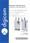
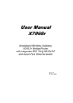
Wireless 3G Gateway HSDPA & HSUPA Station Fast Internet with 7.2 Mbps UMTS Technology Simultaneous Internet and Voice call Send and Receive SMS Built-in ADSL 2/2+ Router function (optional) 3G Gateway Series User’s Guide rev. 2.0 09/2009 2 Mbps Upload transmission 3G Gateway Series Index - Preface INDEX PREFACE.......................................................................................................................................................... II DECLARATION CE of CONFORMITY............................................................................................................ II Assistance and Contacts....................................................................................................................... II Restriction of use of Wireless Radio Equipment using the 2.4GHz ISM frequency band............................... III SAFETY WARNINGS.......................................................................................................................................IV 1. INTRODUCTION............................................................................................................................................. 1.1 1.1.DESCRIPTION........................................................................................................................................ 1.1 1.2.CONNECTORS PANEL........................................................................................................................... 1.2 1.2.1. 3G SoHo Connectors..............................................................................................................................................1.2 1.2.2. 3G SoHo PLUS Connectors....................................................................................................................................1.2 1.2.3. 3G BackUP Connectors..........................................................................................................................................1.3 1.2.4. 3G CorporaTe Connectors.................................................................................................................................1.3 1.2.5. 3G WLL Connectors.................................................................................................................................................1.3 1.3.DISPLAY.................................................................................................................................................. 1.4 1.4.LED.......................................................................................................................................................... 1.5 1.5.PARTS CHECK....................................................................................................................................... 1.5 2. HARDWARE INSTALLATION........................................................................................................................ 2.1 2.1.BATTERY BACKUP................................................................................................................................. 2.3 2.1.1.Replacement of battery.......................................................................................................................................2.3 2.2.PIN AND PUK MANAGEMENT............................................................................................................... 2.4 3. WEB CONFIGURATION................................................................................................................................. 3.1 3.1.QUICK CONFIGURATION...................................................................................................................... 3.2 3.1.1. Phone Call..................................................................................................................................................................3.2 3.1.2. 3G Data Call.................................................................................................................................................................3.2 4. HOME.............................................................................................................................................................. 4.1 5. CONFIGURATION.......................................................................................................................................... 5.1 5.1.LAN.......................................................................................................................................................... 5.1 5.1.1.Ethernet.....................................................................................................................................................................5.1 5.1.2. Wireless Network...................................................................................................................................................5.2 5.1.3. DHCP Server...............................................................................................................................................................5.7 5.2.WAN........................................................................................................................................................ 5.9 5.2.1. WAN Configuration................................................................................................................................................5.10 5.2.2.ADSL Configuration . ............................................................................................................................................5.11 5.2.3. 3G Configuration...................................................................................................................................................5.16 5.2.3.1.Remote Activation..............................................................................................................................................5.17 5.2.4. DNS...............................................................................................................................................................................5.19 5.3.VOICE CONFIGURATION.................................................................................................................... 5.20 5.3.1.Voice Configuration.............................................................................................................................................5.20 5.3.1.1.Mobile Extension – Mex Application...................................................................................................................5.21 5.3.1.2.FXO calls route to...............................................................................................................................................5.22 5.3.2.FXS................................................................................................................................................................................5.22 5.3.3.FXO...............................................................................................................................................................................5.24 5.3.4. UMTS.............................................................................................................................................................................5.25 5.3.5.FXS Routing table...................................................................................................................................................5.25 5.3.5. UMTS Routing table...............................................................................................................................................5.27 5.3.6.FXO Routing table..................................................................................................................................................5.27 5.3.7. Supplementary services.....................................................................................................................................5.28 5.4.SYstem................................................................................................................................................ 5.30 5.4.1.Firmware Upgrade.................................................................................................................................................5.30 5.4.2. Backup & Restore...................................................................................................................................................5.31 5.4.3. Commit & Reboot.....................................................................................................................................................5.32 5.4.4. User Management..................................................................................................................................................5.32 5.4.5.Time Zone...................................................................................................................................................................5.32 5.5.ADVANCED........................................................................................................................................... 5.35 5.5.1.IGMP Proxy................................................................................................................................................................5.35 5.5.2.IP Routing..................................................................................................................................................................5.35 5.5.3. Dynamic DNS..............................................................................................................................................................5.36 5.5.4. WEB Configuration ...............................................................................................................................................5.37 5.6.FIREWALL............................................................................................................................................. 5.37 5.6.1.IP Filtering................................................................................................................................................................5.37 6. SAVE & REBOOT........................................................................................................................................... 6.1 7. LOGOUT......................................................................................................................................................... 7.1 I 3G Gateway Series Index - Preface All rights reserved; no part of this publication may be reproduced, stored in a retrieval system, or trasmitted in any form or by any means, electronic, otherwise, without the prior written permission of Digicom S.p.A. The contents of this booklet may be modified without notice. Every possible care has been taken in testing and putting together all the documentation contained in this booklet, however Digicom can not take any responsability brought by the use of this booklet. PREFACE In order to guarantee your safety and a correct functioning, be sure to follow these safety warnings. The whole set (with cables included) must be installed in a place lacking of or distant from: • Dust, humidity, high temperatures and direct exposure to sunlight. • Heat irradiating objects, which may damage your device or cause any other problem. • Objects producing a high electromagnetic field (Hi-Fi speakers, etc.). • Corrosive liquids or chemical substances. ENVIRONMENTAL CONDITIONS Environment temperature: from 0 °C to +40 °C Relative humidity: from 20 to 80 % n.c. Any sudden change in temperature and humidity must be avoided. CLEANING INFORMATION Use a soft dry cloth and avoid any solvents or abrasive materials. SHOCKS OR VIBRATIONS Caution against shocks or vibrations. BACKUP BATTERY (optional) WARNING: this device can be supplied with a backup battery. This battery may get burnt, explode or cause serious burnings. DO NOT disassemble, weld, burn or throw the battery into water. Keep out of children. Replace only with a same model battery and reserve the operation only to qualified staff. The use of a different battery may cause fire hazard or explosions. Italian laws consider batteries as dangerous urban waste that must be disposed according to the law provisions in force (Italian DPR 915/82 and local provisions). The backup battery is excluded from warranty. DECLARATION of CONFORMITY We, Digicom S.p.A., with registered office at Cardano al Campo (VA - Italy) - Via Volta 39, declare under our sole responsibility, that the products named 3G SoHo, 3G SoHo PLUS, 3G BackUP, 3G Corporare, 3G WLL, to which this declaration refers to, satisfy the essential requirements of following Directive: - 1999/5/CE 9th March 1999, R&TTE (concerning radio equipment and telecommunication terminal equipment and the acknowledgment of their conformity) Law Decree 9th May 2001, n.269, (G.U. n. 156 of 7-7-2001). As indicated in conformity with the requirements of following Reference Standards or of other regulations documents: EN 300 328 EN 301 489-1 EN 301 489-7 EN 301 489-24 EN 301-908-1 EN 301-908-2 EN 60950-1 This device can be used in the following countries: IT, DE, ES, PT, BE, NL, GB, IE, DK, GR, CH Assistance and Contacts Most of questions can be answered by looking up in the Support > F.A.Q. section of our website at www.digicom.it. If you can’t find the answer you’re looking for, please contact our Technical Support at [email protected] II 3G Gateway Series Index - Preface Restriction of use of Wireless Radio Equipment using the 2.4GHz ISM frequency band This equipment complies with european standards in matter of electromagnetic compatibility, interference and safety. This equipment operates in the 2.4GHz Wireless radio bandwidth, regulated by the European 1999/5/CE Directive. It can be freely used in those countries which are not specifically applying restrictions. Restrictions of use in France Indoor The maximum transmit power (EIRP) is limited to 100mW (20 dBm) within the 2400-2483,5MHz frequency range Outdoor The maximum transmit power (EIRP) is limited to 100mW (20 dBm) within the 2400-2454MHz frequency range The maximum transmit power (EIRP) is limited to 10mW (10 dBm) within the 2454-2483,5MHz frequency range Please check www.art-telecom.fr for updates and further informations. Restrictions of use in France This equipment can be used freely within private areas. Should the equipment being used in public areas or outside private areas, the user must apply a general authorization and inform the national telecommunication organization. Please refer to www.comunicazioni.it for updates and further informations. If the equipment allows to modify the transmit power level or change of the antenna type, the user must ensure not to exeed the 100mW (20 dBm) limit in any case or final setup. INFORMATION FOR USERS According to the 2002/95/CE, 2002/96/CE and 2003/108/CE Directives, relative to reduction in the use of hazardous substances in electrical and electronic apparatus, as well as to disposal of waste materials. The symbol of a crossed box applied on the apparatus or on its package indicates that at the end of its useful life the product must be collected separately from other waste materials. The user must therefore take the apparatus which has reached the end of its useful life to appropriate separate collection centres for electronic and electro-technical waste materials, or deliver it back to the reseller when purchasing new apparatus of an equivalent type, giving one piece in for one piece out. Suitable separate waste collection for then sending the cast-off apparatus for recycling, treatment and environmentally friendly disposal, contributes towards preventing any possible negative effects on the environment and on health and encourages recycling of the materials the apparatus is made up of. Unauthorised disposal of the product by the user will lead to payment of the administrative sanctions in force in the country where it is put on the market. III 3G Gateway Series Index - Preface SAFETY WARNINGS Read these instructions and norms carefully before powering the 3G Gateway. Violation of such norms may be illegal and cause hazard situations. For any of the described situations please refer to the specific instructions and norms. The 3G Gateway is a low power radio transmitter and receiver. When it is ON, it sends and receives radio frequency (RF) signals. The 3G Gateway produces magnetic fields. Do not place it next to magnetic supports such as floppy disks, tapes, etc. Operating your 3G Gateway close to other electrical and electronic equipment - such as a television, phone, radio or a personal computer - may cause interferences. INTERFERENCES The 3G Gateway, like all other wireless devices, is subject to interferences that may reduce its performances. ROAD SAFETY Do not use your 3G Gateway while driving. In case of use on cars, you must check that the electronic equipment is shielded against RF signals. Do not place the 3G Gateway in the air bag deployment area. AIRCRAFT SAFETY Switch off your 3G Gateway when on board aircrafts by disconnecting the power supply and deactivating the internal backup battery. Using GSM devices on aircrafts is illegal. HOSPITAL SAFETY Do not use the 3G Gateway near health equipment, especially pacemakers and hearing aids, in order to avoid potential interferences. Take care when utilizing the 3G Gateway inside hospitals and medical centres, which make use of equipment that could be sensitive to external RF signals. Switch it off when use is expressly forbidden. EXPLOSIVE MATERIALS Do not use the 3G Gateway in refuelling points, near fuel or chemicals. Do not use the 3G Gateway where blasting is in progress. Observe restrictions and follow any specific regulation or instruction. INSTRUCTIONS FOR USE Do not use the 3G Gateway in direct contact with the human body and do not touch the antenna if not strictly necessary. Use approved accessories only. Consult documentation regarding any possible device connected to the 3G Gateway. Do not connect incompatible products. IV 3G Gateway Series Introduction 1. INTRODUCTION Dear Customer, thanks for puchasing 3G Gateway. You will now be able to access the Internet using 3G connection or ADSL connection (optional). This User's Guide will show you how to connect your 3G Gateway and to customize its configuration to get the most out of your new product. 1.1. DESCRIPTION 3G Gateway identifies a range of Digicom 3G routers: 3G SoHo, 3G SoHo PLUS, 3G BackUP, 3G Corporate and 3G WLL. This user manual describes all the functionalities of 3G Gateway. The table shows the main differences among 3G Gateway versions: Functionality UMTS (HSUPA) ADSL (2/2+) 1 LAN 10/100 Tel FXS Line FXO 1 SIM Holder 2 SIM Holder In/Out Display WiFi Battery Backup Housing 3G SoHo Yes No Yes Yes No Yes No No Yes Yes Optional 3G SoHo PLUS Yes Yes Yes Yes Yes Yes No No Yes Yes Optional 3G BackUP Yes Yes Yes No No Yes Optional No No Yes Optional 3G Corporare Yes Yes Yes Yes Yes Yes Optional Optional No Yes Optional 3G WLL Yes No Yes Yes No Yes No No No Yes Yes 1.1 3G Gateway Series Introduction 1.2. CONNECTORS PANEL A B C D E F G H CONNECTOR TEL (1,2) LAN PWR SIM ADSL LINE RESET FACTORY DESCRIPTION RJ11 FXS connectors for analog phones or PABX trunks (parallel) RJ45 connector for ethernet cable Power supply connector SIM connector. The models supporting double SIM will have 2 SLOTs RJ11 connector for ADSL line (available on models with ADSL router only) RJ11 FXO connectors for PABX extensions Reset (Power OFF/ON). For Backup battery models, power the device OFF and press it for 10 sec Reset to factory default A C B G D H E 1.2.1. 3G SoHo Connectors 1.2.2. 3G SoHo PLUS Connectors 1.2 F 3G Gateway Series Introduction 1.2.3. 3G BackUP Connectors 1.2.4. 3G Corporate Connectors 1.2.5. 3G WLL Connectors 1.3 3G Gateway Series Introduction 1.3. DISPLAY 3G Gateway (SoHo models) is equipped with a 65.000 colors display where you can see the information on the gateway operation status. 29 ADSL 23 vodafone A 12:27 B 3G ON-LINE 12/06/2008 SYMBOL DESCRIPTION SMS It indicates the presence and the numbers of unread SMS in the SIM Missed calls Battery Backup ADSL ADSL Signal It indicates the presence and the number of missed calls It indicates the Backup battery status (optional) ADSL connected ADSL disconnected It indicates the status of GSM signal GSM Mode Operator Connession Time & Date 3G indicates the roaming range of 3G network Operator where the SIM is registered It indicates the status of data connection It indicates the time and date WiFi WiFi enabled LAN A computer, switch or other network device is correctly connected to the LAN port ADSL ADSL A B C 1.4 C 3G Gateway Series Introduction 1.4. LED 3G gateway version with no display, will supply the information about the device status through 7 leds. LED Power 3G WiFi LAN TEL LINE ADSL STATUS DESCRIPTION Off Device off On Device correctly powered Off SIM not ready Flashing Green SIM ready and no 3G data connection on On Green SIM ready and 3G data connection on Flashing Red SIM ready and no 2G data connection on On Red SIM ready and 2G data connection on Fast Flashing Red Insert PIN/PUK Off WiFi disabled On WiFi enabled Off No device connected on the Ethernet port Computer, switch or other network device correctly connected to the LAN port On Off Line not engaged Flashing Line engaged Off Line not engaged Flashing Line engaged Flashing ADSL line (physical level) not available On ADSL line (physical level) available 3G HSPA ROUTER 3G Wi-Fi LAN TEL LINE ADSL PWR 1.5. PARTS CHECK The package will contain the following items: • 3G Gateway • Power adapter • Quick Guide • Wi-Fi antenna • GSM antenna • Ethernet cable RJ45-RJ45 1.5 3G Gateway Series Hardware Installation 2. HARDWARE INSTALLATION Just three steps to operate with 3G Gateway: 1. Connect the GSM antenna and the WiFi antenna (the pictures show two different models). 2. Insert the SIM (we recommend to disable the PIN). For a correct operation turn 3G Gateway off. SIM 1 SIM 2 3. Connect the power supply and turn 3G Gateway on. Now you can connect a phone to the connector Tel 1 and you will be able to make and receive calls. (Function not supported by 3G BackUP). 2.1 3G Gateway Series Hardware Installation The next image shows the other connection types: Power supply RJ45 RJ11 RJ11 INTERNET ADSL Line Extention PABX LAN To configure 3G Gateway and/or surf the internet, connect the computer through the LAN port. If more than one device must be connected, use an external switch. To use the WiFi, simply enable this option in the configuration web pages. ADSL If your 3G Gateway supports the ADSL router, connect the line to the ADSL port. LINE If your 3G Gateway supports the FXO interface, connect the PABX extension or public line to the LINE port. Display & LED Through the dispaly or the leds it is possible to check 3G Gateway status. 2.2 3G Gateway Series Hardware Installation 2.1. BATTERY BACKUP The battery backup is placed into the product. The connection of the battery is at the installer or at the end user’s care. Battery backup features: Li-ion 7,4V 1700mAh To connect the battery backup: • Power off the device and remove the plastic cover by turning the screws • Insert the connector into the card as shown in picture • Close the upper plastic cover and secure it by using the two screws. 2.1.1. Replacement of battery The battery is sticked on the device. To replace it, disconnect the connector from the card and gently remove the battery. Note: You are advised to use battery supplied by Digicom only. 2.3 3G Gateway Series Hardware Installation 2.2. PIN AND PUK MANAGEMENT The PIN request is always enabled on the SIMs; to use them inside 3G Gateway you can: 1. Disable the PIN request on the SIM (through a cellular phone). 2. Insert the PIN in the 3G Gateway configuration. At power on, the device will send the PIN to the SIM. 3G Gateway will show the PIN request from the SIM on the display (Insert PIN) or through the fast blinking of 3G led (red) in the versions without display. You can setup 3G gateway in two ways: A. WEB based configuration (3G Umts menu). Click Save&Reboot to enable the configuration. B. Through the phone keyboard (set the DTMF selection) connected to TEL1 or TEL2 connector (available in the version with TEL-FXS port only). Lift the receiver, you will hear the tone of PIN code request (two close beeps repeated with a pause). 1. Digit the PIN code using the phone keyboard and confirm by pressing “#” (set on the phone the DTMF selection) PIN# code (i.e.0123#) 2. To cancel the PIN code insertion, hang up before you confirm the PIN code with “#”. 3. If the PIN code is correct, you will hear the correct configuration tone (two tones repeated), or the tone for wrong PIN (three tones repeated). 4. Hang up to complete the procedure. Now 3G Gateway will automatically save the PIN in the configuration and it will make a Reset. 5. At 3G Gateway start up, the PIN is no more asked for and the SIM will register to the network. PUK management The PUK code can be inserted with the same procedure as for the PIN insertion, through the phone keyboard (available in the version with TEL-FXS port only) or by inserting the SIM inside a mobile phone. ATTENTION: the PIN and PUK codes are indicated on the PIN-PUK card supplied by the Telecom Operator when you buy the SIM card. If a wrong PIN number is inserted for 3 times, it will be necessary to insert the PUK code followed by a new PIN code. After 10 wrong PUK codes, the SIM card will be blocked permanently and you have to substitute it. 2.4 3G Gateway Series WEB Configuration 3. WEB CONFIGURATION Getting Started with the Web pages 3G Gateway includes a series of Web pages that provide an interface to the software installed on the device. It allows you to configure the device settings to meet the needs of your network. You can access it through a web browser on a PC connected to the device. Accessing the Web pages To access the web pages, you need the following: • A laptop or PC connected to the LAN port on the device. To enter the configuration menu you must set on the computer an IP address of the same LAN of 3G Gateway; you can set the address statically or using the assignment through the DHCP Server. Windows® XP • From the Start menu select -> Control Panel -> Network connections. • Select LAN Connection, display the Properties, select Internet Protocol (TCP/IP) and press on Properties button. • If using a DHCP Server, set Obtain automatically an IP Address, 3G Gateway will appropriately configure the IP addresses. • A web browser installed on the PC. For the best display quality, use latest version of Internet Explorer, Netscape or Mozilla Firefox. from any of the LAN computers, launch your web browser, type the following URL in the web address (or location) box, and press Enter on your keyboard: http://192.168.1.254 (user: admin, pwd: admin) The web pages for the configuration have a column on the left, where you find the configuration menus, and a central part where you can see the settings and modify them. The main menus are the following: Home, Configuration, Save & Reboot and Logout. 3.1 3G Gateway Series WEB Configuration 3.1. QUICK CONFIGURATION This paragraph describes the main parameters to be set to make and receive calls (if the FXS “TEL” interface is supported) and to start the Internet surfing in 3G mode. 3.1.1. Phone Call For FxS interface versions only. To start making/receiving calls you must have followed the instructions of the Hardware Installation chapter: • Connect the GSM antenna • Insert the SIM (we recommend to disable the PIN) • Connect a phone to the connector Tel 1 • Connect the power supply and turn 3G Gateway on • As soon as the display (or 3G led) will show the operator name, you will be able to make and receive calls. 3.1.2. 3G Data Call To make a call in 3G mode, check that the WAN is set to 3G (Configuration menu, WAN, WAN configuration). • In the 3G UMTS menu insert the information (depending on the GSM operator you are using) for APN, Username and Password (for some operators the APN is sufficient). • Define the connection mode: Always on: 3G Gateway will enable 3G connection at power on. If some disconnections should occur, the Gateway will try to restore them automatically. Manually: In this mode the user manually decides when the connection must be enabled and for how long. To enable (connect) andd disable (disconnect) 3G connection, use the push buttons in the Home page. Note: Verify with your telecom operator the profile of the SIM you are using for the Internet connection. 3.2 3G Gateway Series WEB Configuration • Save the configuration and reboot the gateway (menu Save & Reboot). • If the ethernet card of the computer connected to 3G Gateway is set to DHCP mode, 3G Gateway will appropriately configure the IP addresses and you will be able to start surfing. • If the ethernet card is configured with static IP addresses, check that the preset Gateway address is the one of 3G Gateway. 3.3 3G Gateway Series Home 4. HOME • The Home menu has various options that allow to verify the device status. • The Home and Status pages display the device overview: 4.1 3G Gateway Series 4.2 Home 3G Gateway Series Configuration 5. CONFIGURATION The Configuration menu has various options for the device configuration. 5.1. LAN 5.1.1. Ethernet This page displays the local network configuration where you can configure: • IP Address: (Enter the Primary IP Address. For example, enter 192.168.1.1) • Subnet Mask: (Enter the Subnet Mask. For example, enter 255.255.255.0) • Host Name • Domain Name • Virtual IP Address: (Select the check box, “Configure Virtual IP address and subnet mask” to specify the Virtual IP Address and Subnet Mask) • MTU (Enter the value of MTU. 1500 is the default value) 5.1 3G Gateway Series Configuration 5.1.2. Wireless Network This page allows you to setup the wireless connection. The following settings are allowed: • Basic • Advanced • WDS Settings • MAC Address Filter • Radius Server Basic Settings Global Setting Select Profile: Select one of the following profiles: 802.11 B/G, 802.11 B Only, 802.11 G Only, 802.11 MIXED_LONG, 802.11 A. If you do not know or have both 11g and 11b devices in your network, then keep the default in 802.11 B/G. Select the option Enable or Disable Wireless Network: Select Country: Channel Selection: Select the channel as Auto or Manual. Network Name (SSID): The ESSID is the unique name of a wireless access point (AP) to be distinguished from another. Make sure your wireless clients have exactly the ESSID as the device, in order to get connected to your network. Hide SSID: You may choose to Hide SSID (Yes/No). This function transmits its ESSID to the air so that when the wireless client searches for a network, the router can then be discovered and recognized. 5.2 3G Gateway Series Configuration Security Settings You can disable or enable with WPA or WEP for protecting the wireless network. Select Security Option:Select the security option from the drop down list. The available security options are: Off – No Encryption, 64 Bit Encryption, 128 Bit Encryption, Wi-Fi Protected Access, Wi-Fi Protected Access 2, and WPA Mixed Mode. Click Confirm WEP Encryption: To prevent unauthorized wireless stations from accessing data transmitted over the network, the router offers highly secure data encryption, known as WEP. If you require high security for transmissions, there are two alternatives to select from: WEP 64 (64 Bit Encrtyption) and WEP 128 (128 Bit Encrtyption) . WEP 128 will offer increased security over WEP 64. Select Key Method: With Pass Phrase you will insert a WEP Pass Phrase and with Direct Key you will insert a Key. WEP Pass Phrase: This is used to generate WEP keys automatically based on the input string and a pre-defined algorithm in WEP64 or WEP128. Key: Enter the key to encrypt wireless data. To allow encrypted data transmission, the WEP Encryption Key values on all wireless stations must be the same as the router. There are four keys for your selection. The input format is in HEX style, 10 and 26 HEX codes are required for WEP64 and WEP128 respectively. WPA (Wi-Fi Protected Access): There are two types of the WPA-PSK and WPA2-PSK. WPA Pass Phrase: The key for network authentication. The input format is in character style and key size should be in the range between 8 and 63 characters. 5.3 3G Gateway Series Configuration Advanced Settings In addition to the settings provided under basic settings, you can specify: Fragmentation Threshold, RTS Threshold, NitroXM PiggyBack, and WMM. WDS Settings Wireless Distribution System is a wireless access point mode that enables wireless link and communication with other access point. Easy to install simply defining peer’s MAC address of the connected AP. 5.4 3G Gateway Series Configuration MAC Address Filter You can specify which wireless PCs can connect to your device. • Select MacAuth • You can select which MAC authorization option as Disable, White List or Black List. • Add MAC Address • Enter the MAC address and click Apply. You can also delete the existing MAC address by clicking Delete. 5.5 3G Gateway Series Configuration Radius Server Radius server configuration is required when user configures the wireless network for Radius Authentication (802.1x EAP) for WPA/WPA2 security. It allows user to configure different accounting and authentication servers or to configure the same server for both authentication and accounting. It allows you to configure (Name, IP Address, UDP Port, Retries, Timeout) settings for the Radius server. Click Add to add the Authentication Server: To enable/disable the radius server: Select Enable or Disable and click Apply. To set the authentication server: • Click Add. • Enter the Name, IP Address, Shared Key, UDP Port, Retries (connection retry time), Timeout, and VAP Port details. • Click Submit. To set the accounting server: Enter the details as described above and click Submit. 5.6 3G Gateway Series Configuration 5.1.3. DHCP Server Global Settings: to enable/disable the DHCP server: Select Enable or Disable and click Apply. In this page you can configure DHCP Relay functionality. Server Settings: you can configure the DHCP server options assigned to the clients. Fixed Host Settings: Select Add Fixed Host and insert IP address and MAC Address. The MAC address should be expressed as 6 hexadecimal pairs seperated by colons, e.g. 00:20:2b:01:02:03 5.7 3G Gateway Series Ip range Settings: Configuration you can configure the IP range assigned to the clients. If you need change the default rule, you must delete the rule present in the web page and insert a new one. 5.2. WAN The WAN menu has the following WAN options: WAN Configuration, ADSL Configuration, 3G UMTS e DNS. 5.8 3G Gateway Series Configuration 5.2.1. WAN Configuration 3G Gateway can manage 2 different WAN types: 3G (HSDPA/HSUPA module) and ADSL (optional, not present on all models). The two interfaces will operate alternatively, not simultaneously. The device can be set to operate in 3 modes: 1. 2. 3. 4. 3G mode only ADSL mode only ADSL + back-up over 3G 3G + back-up ADSL Note: Point 2 and 3 for ADSL interface versions only. If you select ADSL + BackUP you will be able to set the backup options in the BackUP section. Backup and Restore can be manually or automatically set. With the manual backUP you will enable the connection through the Connect and Disconnect buttons in the Home Page. If the user has connection problems (the information will be displayed) he can manually enable the UMTS connection. An eventual Connect for the UMTS connection automatically disconnects the ADSL. If the user disconnects the UMTS connection, 3G Gateway will try to connect through the ADSL line. Automatic backup With this setup 3G Gateway automatically pass from ADSL to UMTS (Backup) connection according to the configuration of BackUP rule menu. • No Ping: the backup/restore occurs only after the status (physical level) of ADSL line has been checked. • Default Gateway: besides the phisical level of ADSL line, also a check (PING) of default Gateway is carried out. In this mode the BackUP is carried out even in case the ping with ADSL UP line fails. It is important to check that normally the Default Gateway answers the PING. • Host: In this mode, besides the physical level of ADSL line, it is carried out also a check (PING) of two addresses that the user can insert. In this mode the BackUP is carried out even in case that with ADSL UP line the ping to both inserted addresses fails. It is important to check that normally the two inserted addresses answer the PING. The backup or the following restore will be carried out if one of the above mentioned cases occurs for a time longer than the one defined in backup timeout or restore timeout (default 90 seconds). 5.9 3G Gateway Series Configuration 5.2.2. ADSL Configuration For ADSL interface versions only. You can configure your internet connection from this page. This page displays the details of existing internet connection, if any. You can perform the following functions from this page: • Connection • Configure ADSL • Specify MAC Spoofing Internet connection configuration Connections • To configure the internet connection: Click Add. Follow the steps described to setup the internet connection. • To edit the internet connection: Click Edit. Configure ATM PVC page opens: 5.10 3G Gateway Series Configuration • Configure ATM PVC page opens: To configure ATM PVC: • Enter the name of PVC in PVC Name. • Configure the ATM PVC by entering the VPI and VCI values provided by the ISP. • Click Next. Configuring Connection Type page opens. To configure the connection type: • Select the Protocol by selecting the radio button for the desired protocol type. • Select the Encapsulation Type from the drop down list. • Select the desired Encapsulation Mode from the drop down list. Configuring WAN IP Settings page opens. 5.11 3G Gateway Series Configuration To configure the WAN IP settings: • Select/Unselect to enable or disable the Access Configurator option. In case you enable the access configurator, enter the value in Access Concentrator. • Select one of the following options: • Obtain an IP address automatically. • Use the following IP address: specify the WAN IP Address. • Click to Enable NAT. • Click to Add Default Route. • Click Next. To configure the broadband user name and password: • Enter the user name in Broadband User Name. • Enter the password in the Password field and confirm it by entering it again in the Confirm Password field. • Specify the network session by selecting Always On, Dial on Demand or Manually Connect option. You can also choose to disconnect after a specified period when no user activity is detected. Also, you can specify “Consider Lanside Traffic Only”. By default, the option Always On is selected. • Click Next. 5.12 3G Gateway Series Configuration ADSL Configuration You can configure your ADSL Attributes in this page. MAC Spoofing • MAC spoofing lets the MyDslModem identify itself as another computer or device. You may need to use this depending on your Internet Service Provider. • To specify MAC Spoofing: • Select either Disabled - MAC Spoofing is not used or Enabled - MAC Spoofing will be used with a MAC address you provide. MAC Spoofing Setup/Confirm page opens based on the option previously selected. • Specify the MAC address in case you enabled the MAC Spoofing. • Click Next to confirm the specified MAC Spoofing settings. 5.13 3G Gateway Series Configuration 5.2.3. 3G Configuration Network mode: You can configure the network selection in: Automatically, GSM only, 3G Only or 3G preferred. Define the connection mode: • Always on: 3G Gateway will enable 3G connection at power on. If some disconnections should occur, the Gateway will try to restore them automatically. • Manually: In this mode the user manually decides when the connection must be enabled and for how long. To enable (connect) and disable (disconnect) 3G connection, use the push buttons in the Home page. With manually connection you can configure the remote activation with SMS or CLI. SMS service center: Number of SMS service center APN, Username e Password: These information depend on operator that must supply them. PIN: If the SIM you are using requires the PIN, you must insert it in this field. Idle Timeout: not supported, for future application. 5.2.3.1. Remote Activation To enable Remote Activation (RA) it is necessary to activate the functionality and set the options in 3G UMTS menu. Code: Anyone: Phone Num: Delete all SMS: 5.14 4 digits code set by user. If ON any mobile phone can enable the remote connection with an SMS. This allows the restriction of enabling remote connection to one number only. The number must be inserted with the international prefix (i.e.. +393351234567). Only the number inserted in Phone Num will be able to activate the remote connection (Anyone option disabled). If enabled, it activates the cancellation of all SMS received after the reception of an SMS concerning the RA application (connection, disconnection and reset). This option is useful in installations without operator to avoid the SIM fills with SMS, blocking the operation of Remote Activation. 3G Gateway Series Configuration Disconnect Timeout: It defines the period of connection (default 600 seconds). After the disconnect timeout the connection is cut down. It is possible to set an high disconnection time and remotely interrupt the connection via WEB (disconnect button) or via SMS (code disconnect) Possibility to remote enable the connection through the Caller ID. Available only if the SIM supports voice calls. Insert 2 phone numbers authorized to remote enable the call (CLI). The numbers must be inserted with the international prefix (i.e. +393351234567) If enabled, 3G Gateway will send a reply SMS after the connection. If disabled, it will activate the connection without sending SMS. The reply SMS is composed by the IP address, get from the network, followed by the text that can be inserted by the side of the check box “sms answer”. CLI activation: Phone Num.1-2: SMS Answer: Select Save & Reboot, press Commit and then Reboot (Last) to save and make the configuration active. 5.15 3G Gateway Series Configuration The Remote Activation functionality can: 1. Enable a remote connection via SMS. The text to be sent to 3G Gateway is ”code connect”. 2. Enable a remote connection with the CLI identification (Caller ID). 3. Remote reset 3G gateway via SMS (power off - power on). The text to be sent to 3G Gateway is ”code reset”. 4. Interrupt a connection (Connection option: Manually) via SMS. The text to be sent to 3G Gateway is ”code disconnect”. NOTES: SMS Syntax The SMS to be sent to 3G Gateway must be composed by: code, blank, text (connect, reset or disconnect) written in small letters. More activation simultaneously If while a Remote Activation connection is active, a new connection message comes, 3G Gateway immediately answers to the new request informing about the IP address in use and restarting the “Disconnect timeout”. Reply SMS “NO IP address” It shows 3G Gateway hasn’t got an IP address from the operator. Send connection SMS again. This can occur for temporary problems of connection or for credit exhausetd. 5.16 3G Gateway Series Configuration 5.2.4. DNS To add a new DNS Relay Server: • Enter the IP address of the DNS Relay Server in IP Address. • Click Add. The page gets refreshed and the IP address of the DNS Relay Server gets listed under IP Address. You can delete an existing DNS Relay Server by clicking. 5.17 3G Gateway Series Configuration 5.3. VOICE CONFIGURATION In this chapter we refer to two different phone interfaces: FXS and FXO. FXS interface corresponds to Tel connectors of 3G Gateway and it can be connected to a phone or to an analog interface of a PABX (trunk side). FXO interface corresponds to LINE connector of 3G Gateway and it can be connected to a PABX extension or to a public analog line. The configurations for FXO interface are available only for 3G Gateway models that support this interface. 5.3.1. Voice Configuration In this page you can configure the general parameters for voice interface. NOTE: Integra is a special application implemented for Movistar / Telefonica Spain operator. 5.3.1.1. Mobile Extension – Mex Application To manage this application, select Mobile EXtension in the Menu. The Mobile EXtension application is performed by 3G Gateway models supporting both FXO and FXS interface. The installation is performed through the connection of FXO interface on the extensions side of the PABX and of a phone on the FXS interface of 3G Gateway. Attention: For Mobile Extension configure FXO calls route to: FXS – DialThoru gateway 5.18 3G Gateway Series Configuration MEx Number GSM/GPRS FXS FXO Phone 1 PSTN ISDN The Mobile Extension (MEx) application allows the diversion of a PABX extension to a mobile phone with the maximum portability. It turns your mobile phone into a PABX extension with the advantage to keep the communication with the PABX, if compared with the traditional call forwarding. For example this permits to forward a call, received on the mobile phone, to an extension during the conversation itself. To enable the call diversion both to the phone connected to the FXS interface and to the mobile phone (Mex Number), enable the Activate option. The activation will be identified with a special dial tone. You can enable/disable the Mobile Extension functionality on the phone connected to the FXS interface. The “Code for DTMF Activation” can be set via web interface (default “**”). Calls to PABX extension connected to the Gateway (Activate option not enabled) All the calls addressed to the PABX extension connected to the Gateway (fxo) will be diverted to the phone connected to the FXS interface (Phone 1). Calls to PABX extension connected to the Gateway (Activate option enabled) Both the phone connected to the FXS interface (FXS Phone) and the number of mobile phone associated to this functionality (Mex Nember) will ring simultaneously when an incoming call arrives to the PABX extension where the FXO interface is connected. If the communication with MEx Number is enabled, it will be possible to restore the communication with the PABX. • From MEx Number you will be able to forward the call to a PABX extension. • Digit “#” on the mobile phone; 3G Gateway will reproduce the flash to the PABX; on the MEx Number it will hear the dial tone and it will possible to dial a PABX extension (i.e. 101). In the meantime the person of the first call is on hold. • When 101 extension answers, you will be able to put it in communication with the first person (who is on hold) simply hanging up or pressing “#” again, the on hold call will be enabled. Note: The “#” character, used as flash button on the mobile phone (MEx Number) can be modified in the (Line – FXO) GSM code for Flash. Calls to the mobile phone number of the SIM in 3G Gateway The calls will be managed according to the setting of UMTS Routing Table menu. Outogoing calls from (Phone 1) The calls will be managed according to the setting of FXS Routing Table menu. 5.19 3G Gateway Series Configuration 5.3.1.2. FXO calls route to With this menu you can configure the redirection of calls received on FXO port to FXS interface (FXS- DialThru gateway) or to GSM/UMTS interface (GSM – FXO gateway). 5.3.2.FXS Configuration of FXS (Tel) interface. Enable CLIR (Caller Line ID Restriction) If CLIR is enabled, 3G Gateway is set not to send its own number (SIM telephone number), the receiver will see “private number”. CLI (Calling Line Identification) FSK It enables the display of the caller’s telephone number on the display of the telephone connected to the Gateway. The Calling party number is transmitted on FXS port by FSK. NONE Disable CLI Timeout for dialing (ms) - Default: 4 sec. Timeout before starting the call (after the last digit). Pause before dialing (s) - Default: 5 sec. Timeout before the automatic dialing of the number insert is UMTS Routing Table (Route to FXS). Flash detection max (ms) It indicates the maximum time of line interruption that the device interprets as Flash. A longer time of line interruption is interpreted as a disconnection. 5.20 3G Gateway Series Configuration Volume Rx and Tx - Default: 7 Set the volume on FXS port, from 0 (silence) to 10 (high +6db). The step is 2db. Autocall Autocall enabled. If after having engaged the 3G Gateway line no number is dialed within the preset Timeout, 3G Gateway will make a call to the number set in “Phone Number” field. Ringing It displays the values (frequency and cadence) of the Ring generated on the FXS port. The parameters can be customized. Signaling If reverse polarity is enabled, 3G Gateway will change the line polarity to notify the call status. Tone It displays the Frequency and Cadence of Dial tone, Busy tone and Congestion tone generated on the FXS port. The parameters can be customized. To enable double frequency tone insert the value in the second column (blank is disabled). Default It reloads the factory settings with the “Tone” values. 5.3.3. FXO Page for the configuration of FXO (Line) interface. Ring before pickup – Default:1 Define the ring numbers before pickup the line. Flash (generation - ms):It’s the line stop time that 3G Gateway reproduces to its FXO interface (to the PABX) when, in the Mobile Extension application, it receives the DTMF set in GSM code for Flash. Volume Rx and Tx Set the volume on FXO port, from 0 (silence) to 10 (high +4,5db). The step is 1,5db. GSM code for Flash (#):It defines the DTMF code that MEX must digit so that 3G Gateway sends a flash to the PABX (FXO) in the Mobile Extension application. 5.21 3G Gateway Series Configuration Call progress detection Tone: 3G gateway checks the Tone parameters (Ringback, Busy and Congestion) in order to define the call status. Line reversal: 3G Gateway checks the polarity reversal in order to define the call status. Ringing Frequency: 3G Gateway checks the set ring frequency define the presence of an incoming call. Tone It checks the Frequency and Tone Cadence range to define the call status. 5.3.4. UMTS C Volume Rx and Tx Set the volume on UMTS interface, from 0 (silence) to 7(high). 5.3.5. FXS Routing table With FXS routing table you can decide to forward the numbers dialed on FXS (phone or PBX trunk) to the GSM or to the FXO. Default is “route to GSM”. C Press Add to insert a new rule. C 5.22 3G Gateway Series Configuration Prefix Prefix used to indentify the rule. Call Enable Yes No call allowed call denied Route to Route to GSM Route to FXO the call will be dialed on GSM network the call will be dialed on FXO line Number of Digits Length of the number to be dialed 0: No check on length of dialed number i.e. Number of digit=3, the rule checks and dials immediately after the 3rd digit End with # Yes No the call will be dialed immediately after dialing “#” the number will be dialed after the “Timeout for dialing”. In this configuration if you insert the “#” in the number, it will be dialed. Digits to remove Number of digit to be removed at the beginning of the number. 0 all numbers will be dialed 1 the number will be dialed without the first number (i.e. 0335123456 will be dialed 335123456) Add string Number or prefix to be added at the beginning of the number. Blank no number will be added 0 the number “0” will be added at the beginning 0039 the prefix “0039” will be added at the beginning 5.23 3G Gateway Series Configuration 5.3.5. UMTS Routing table The calls received on the UMTS interface can be rejected or forwarded on the FXS or FXO interface. Default is “route to FXO”. Press Add to insert a new rule. Incoming Calling number will be analyzed to apply the rule. Route to It defines the calls management: to reject of to forward to FXS or FXO. Dial Insert the number to be dialed on FXO or FXS interfaces. If the parameter is blank the caller will hear the Dial Tone. 5.3.6. FXO Routing table In order to enable this menu, the parameter FXO calls route to in Voice configuration menu must be set to GSM – FXO gateway. With FXO routing table you can decide to permit (call enable yes) or deny (call enable no) the call according to the prefix number dialed. The call will be dialed through GSM/UMTS module. 5.24 3G Gateway Series Configuration Press Add to insert a new rule. Prefix Prefix used to indentify the rule. Call Enable Yes No call allowed call denied Number of Digits Length of the number to be dialed 0: No check on length of dialed number i.e. Number of digit=3, the rule checks and dials immediately after the 3rd digit End with # Yes No the call will be dialed immediately after dialing “#” the number will be dialed after the “Timeout for dialing”. In this configuration if you insert the “#” in the number, it will be dialed. Digits to remove Number of digit to be removed at the beginning of the number. 0 all numbers will be dialed 1 the number will be dialed without the first number (i.e. 0335123456 will be dialed 335123456) Add string Number or prefix to be added at the beginning of the number. Blank no number will be added 0 the number “0” will be added at the beginning 0039 the prefix “0039” will be added at the beginning 5.25 3G Gateway Series Configuration 5.3.7. Supplementary services The supplementary services must be supported by the mobile/SIM operator you use in order to be managed. Call waiting The Call Waiting service allows to be informed of an incoming call when you are already in a conversation. To answer the incoming call, put on Hold the current conversation by pressing R2 (flash+2). Pressing R2 again you can switch from a conversation to another. To close the current call and take the one on hold, press R1 (flash+1). Multiparty service It enables a simultaneous conversation with 2 people. To enable the Multiple Conversation press R3 (flash+3) on the phone connected to 3G Gateway. Here below the services managed by 3G Gateway (depending on the mobile/SIM operator you use). No WEB configuration menu must be enabled. HOLD During a conversation the user can put the call on hold by pressing R (flash) on the phone connected to 3G Gateway. Pressing R again the on hold call will be restored. ACO, Additional Call Offering After the conversation (R) has been put on hold, the user will hear the dial tone and will be able to make a second call. With R1, R2 and R3 you will be able to manage to simultaneous calls (see Call waiting and Multiparty service). 3G Gateway manages the supplementary services in two ways, from web page or from DTMF (it will be sufficient to digit some codes from the phone connected to the FXS interface). In the web page there are some push buttons to Enable, Disable and Verify the state of the service. Before using the Call Barring you must insert the password used by your mobile operator to manage these services. 5.26 3G Gateway Series Configuration Table with DTMF codes used for the supplementary services: Call Forwarding Unconditioned (all call) Busy No Answer Out of reach Enable *21*number# **21*number# *67*number# **67*number# *61*number# **61*number# *62*number# **62*number# Disable #21# ##21# #67# ##67# #61# ##61# #62# ##62# Verify *#21# Call Barring Incoming Calls Incoming if Roaming Outgoing Calls Outgoing International Calls Outgoing International call except to home Enable *353*password# *35*password# *351*password# *333*password# *33*password# *331*password# *332*password# Disable #353*password# #35*password# #351*password# #333*password# #33*password# #331*password# #332*password# Verify *#353# *#35# *#351# *#333# *#33# *#331# *#332# Call Waiting Call Waiting Enable *43* Disable #43# Verify *#43# *#67# *#61# *#62# 5.4. SYstem 5.4.1. Firmware Upgrade This page displays the current version of the firmware and lets you upgrade to the latest version. 5.27 3G Gateway Series Configuration • Specify the location of firmware file – Click Browse to specify the path where the firmware files are located and click Upgrade. 5.4.2. Backup & Restore To save the backup configuration file: Click Backup. A message window opens prompting you to save the file. • Click Save. • Specify the path where the file is to be saved and click Save. To restore the previously saved configuration. • Click Browse to specify the path of the saved configuration file and click Open. • Click Upgrade WARNING: Do not restart your router during configuration restore process. A message appears indicating the status of restoration: • Click restart to save new configuration. 5.4.3. Commit & Reboot Follow the steps described under 6.0 Save & Reboot chapter. 5.28 3G Gateway Series Configuration 5.4.4. User Management This submenu lets you change the password of user and admin accounts. 3.4.5. Time Zone This submenu lets you configure the SNTP client and server settings. By default, SNTP Client Configuration page opens when you click this submenu. Configuring the SNTP Client To configure the SNTP client: • Select Set the Clock Manually and specify the time in System Clock in YYYY:MM:DD:HH:MM:SS format. • Select the Time Zone from the drop down list. • Specify whether the day light savings applies by selecting Day/Light Savings. • Specify the Mode by selecting it from the drop down list. The available modes are: None, Unicast, Broadcast, and Anycast. • Specify the retry time, timeout, and poll interval in Retries, Timeout, and PollInterval respectively. The time range is specified against each of these fields. • Click Apply. 5.29 3G Gateway Series Configuring the SNTP Server This submenu lets you add or delete servers. To configure the SNTP server: Select one of the options: • Host Name • IP Address Enter the required information and click Add. 5.5. ADVANCED 5.5.1. IGMP Proxy Configure this proxy to run a server on your local network that can be accessed from the Internet. To enable IGMP proxy: • Select the connection from Internet Connection drop down list. • Select IGMP Proxy Enabled. • Click Apply. 5.30 Configuration 3G Gateway Series Configuration 5.5.2. IP Routing You can configure IP routing by: • Static Routing • Dynamic Routing Static Routing • To set static routing: Click Add. Add New Static Route page opens. • Enter the destination IP Address and Netmask. • Enter the Gateway IP Address and Interface, where the packets are to be forwarded. • Click Apply. 5.31 3G Gateway Series Dynamic Routing To enable the dynamic routing: • Click Edit. • Select the RIP Version as 1, 2 or both. • Select the Operation Mode as Active, Passive, or Send Only. • Select Enabled. • Click Apply. 5.5.3. Dynamic DNS To enable the dynamic DNS: • Click to select Enabled for Dynamic DNS. • Specify the Internet Connection, User Name, Password, Email, Key, Wildcard, Domain Name, and Status. • Click Apply. 5.32 Configuration 3G Gateway Series Configuration 5.5.4. WEB Configuration Specify the method by which you wish to access the router. 5.33 3G Gateway Series Configuration 5.6. FIREWALL 5.6.1. IP Filtering To specify the IP filter settings: Enable/disable the IP filter by selecting Enabled/Disabled. Click Apply. Port Filters Edit or delete the port filters by clicking Edit or Delete. IP Filters To add an IP filter: • Click Add. Add New Outbound IP Filtering page opens: • • • • Enter the name of filter rule in Filter Rule Name. Select the filter policy from the Select Policy drop down list. Select one of the option for the direction of filter packets: Outbound traffic, Inbound traffic, Both Specify the Port Filter Rule by specifying the Protocol, Source IP Range, Source Port Range, and Status (Enabled/ Disabled). 5.34 3G Gateway Series Configuration • Specify the IP Validator Rule by specifying the IP Address type (Single, Subnet), IP Address, Netmask, and Status (Enabled/ Disabled). • Click Apply. 5.6.2. Domain Filtering To specify domain filter settings: • Specify the rule action as Allow or Deny and click Apply. • Enter the filter details such as Filter Name, Policy Name, Domain Filter, Start Time (hh:mm:ss), End Time (hh:mm:ss). • Click Add. 5.6.3. Intrusion detection 5.35 3G Gateway Series Configuration 5.7. VIRTUAL SERVER 5.7.1. Virtual server 5.7.2. DMZ A DMZ (DeMilitarized Zone) host is a computer on your network that can be accessed from the Internet regardless of NAT, port forwarding and IP filter settings. A DMZ is often used to host Web servers, FTP servers etc that need to be accessible from the Internet. Setting up a DMZ has implications on the security of your network. Set-up a DMZ only if you understand the consequences. Port forwarding settings will override your DMZ setting. To setup a DMZ Host: • Select the WAN interface and click Edit. • Select Forwarded to the DMZ Host • Enter the IP address of the computer you wish to place in the DMZ • Click Apply. 5.36 3G Gateway Series Configuration 5.8. SMS This menu allow you to read and send SMS directly from 3G Gateway. 5.9. Security Event: in the application ADSL+back-up 3G or 3G+back-up ADSL the 3G gateway can send a SMS up to two phone number in order to inform that it’s in back-up. In the SMS the 3G gateway we will insert a public IP address received from the network. 5.37 3G Gateway Series Save & Reboot 6. SAVE & REBOOT This submenu lets you reboot the modem. You can reboot form the following configurations: Last Configuration Factory Configuration To reboot the modem: Select Reboot From as Last or Factory. Click Reboot. A message appears displaying the status of rebooting: A page displaying the overview of device information opens. 6.1 3G Gateway Series Logout 7. LOGOUT This menu allow you to logout from the web configuration. 7.1 Italy 21010 Cardano al Campo VA via Alessandro Volta 39 http://www.digicom.it