1
Front & Rear Panels—Continued
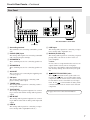
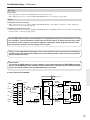
Rear Panel
1 2
3
6 7 8 90AB C
4
5
This illustration is for A-9755.
(A-9755 only)
A Grounding terminal
K LINE input
This terminal is for connecting a turntable’s ground
wire.
B PHONO (MM) input
This analog audio input is for connecting a component’s analog audio output (TV, etc.).
L MAIN IN (A-9755 only)
This analog audio input is for connecting a turntable
with a moving-magnet cartridge.
This analog audio input is for connecting a separate
preamp when you want to use the A-9755 as a
power amplifier.
C SPEAKERS A
These terminal posts are for connecting speaker set
A.
Caution:
Do not connect a component that does not have an
output volume control, such as a CD player,
because the sound will be output at maximum volume and may damage the A-9755 and your speakers.
D SPEAKERS B
These terminal posts are for connecting speaker set
B.
E AC INLET
This connector is for connecting the supplied power
cord (see page 5).
F CD input
This analog audio input is for connecting a CD
player’s analog audio output.
G TUNER input
This analog audio input is for connecting a tuner’s
analog audio output.
M
REMOTE CONTROL jacks
These
(Remote Interactive) jacks can be connected to the
jacks on your other Onkyo audio
components. The A-9755/A-9555’s remote controller can then be used to control all of your components. To use
, you must make an analog audio
connection between the A-9755/A-9555 and each
component.
H TAPE IN/OUT
This analog audio input and output are for connecting a cassette deck with an analog audio input and
output.
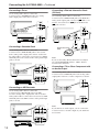
See pages 10–13 for connection information.
I MD IN/OUT
This analog audio input and output are for connecting an MD recorder with an analog audio input and
output.
J HDD IN
This analog audio input is for connecting a component’s analog audio output (RI Dock, etc.).
7