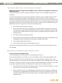
1
NRV10
8x2 Analog Mixer with 10 x 10 FireWire Digital Audio Interface and Effects
User Guide
English
Table of Contents
Introduction
. . . . . . . . . . . . . . . . . . . . . . . . . . . . . . . . . . . . . . . . . . . . . . . . . . . . . . . . .3
What’s in the Box . . . . . . . . . . . . . . . . . . . . . . . . . . . . . . . . . . . . . . . . . . . . . . . . . . . . . . 3
About the NRV10. . . . . . . . . . . . . . . . . . . . . . . . . . . . . . . . . . . . . . . . . . . . . . . . . . . . . . . 4
Features and Technical Specifications . . . . . . . . . . . . . . . . . . . . . . . . . . . . . . . . . . . . 5
System Requirements . . . . . . . . . . . . . . . . . . . . . . . . . . . . . . . . . . . . . . . . . . . . . . . . . . 5
Controls and Connectors Overview . . . . . . . . . . . . . . . . . . . . . . . . . . . . . . . . . . . . . . . 6
Controls and Connectors Descriptions. . . . . . . . . . . . . . . . . . . . . . . . . . . . . . . . . . . . . 7
The Control Panel . . . . . . . . . . . . . . . . . . . . . . . . . . . . . . . . . . . . . . . . . . . . . . . . . . . . . 11
Global Controls . . . . . . . . . . . . . . . . . . . . . . . . . . . . . . . . . . . . . . . . . . . . . . . . . . . . . . 11
. . . . . . . . . . . . . . . . . . . . . . . . . . . . . . . . . . . . . . . . . . . . . . . . . . 11
. . . . . . . . . . . . . . . . . . . . . . . . . . . . . . . . . . . . . . . . . . . . . . . . . . . . 12
Meters View Options
Settings Options
Meters Page . . . . . . . . . . . . . . . . . . . . . . . . . . . . . . . . . . . . . . . . . . . . . . . . . . . . . . . . 12
Hardware Page . . . . . . . . . . . . . . . . . . . . . . . . . . . . . . . . . . . . . . . . . . . . . . . . . . . . . . 13
About Page . . . . . . . . . . . . . . . . . . . . . . . . . . . . . . . . . . . . . . . . . . . . . . . . . . . . . . . . . 14
Using the Analog Mixer . . . . . . . . . . . . . . . . . . . . . . . . . . . . . . . . . . . . . . . . . . . . . . . . 15
Project Studio Recording . . . . . . . . . . . . . . . . . . . . . . . . . . . . . . . . . . . . . . . . . . . . . . . . 15
Live Recording . . . . . . . . . . . . . . . . . . . . . . . . . . . . . . . . . . . . . . . . . . . . . . . . . . . . . . . 16
Live Performance Mixing . . . . . . . . . . . . . . . . . . . . . . . . . . . . . . . . . . . . . . . . . . . . . . . . 16
Using the Cue Buss . . . . . . . . . . . . . . . . . . . . . . . . . . . . . . . . . . . . . . . . . . . . . . . . . . . 16
Using the FireWire Connection . . . . . . . . . . . . . . . . . . . . . . . . . . . . . . . . . . . . . . . . . . 17
Routing and Monitoring with Your DAW . . . . . . . . . . . . . . . . . . . . . . . . . . . . . . . . . . . . . . . 17
Sending Tracks to Your DAW
. . . . . . . . . . . . . . . . . . . . . . . . . . . . . . . . . . . . . . . . . . . . . 17
. . . . . . . . . . . . . . . . . . . . . . . . . . . . . . . . . . . . . . . . . . . . 17
Using the Pre/Post-EQ Switch
Monitoring Audio Live While Recording to Your DAW: . . . . . . . . . . . . . . . . . . . . . . . . . . . . . . 18
. . . . . . . . . . . . . . . . . . . . . .
.
Tape Return Monitoring – Summed Return Channels .
Monitoring an Independent Mix Using Aux Send 1 . . .
Returning Tracks from Your DAW. . . . . . . . . . . . .
Local Monitoring
Tape Return Monitoring – Individual Mixer Channels .
.
.
.
.
.
.
.
.
.
.
.
.
.
.
.
.
.
.
.
.
.
.
.
.
.
.
.
.
.
.
.
.
.
.
.
.
.
.
.
.
.
.
.
.
.
.
.
.
.
.
.
.
.
.
.
.
.
.
.
.
.
.
.
.
.
.
.
.
.
.
.
.
.
.
.
.
.
.
.
.
.
.
.
.
.
.
.
.
.
.
.
.
.
.
.
.
.
.
.
.
.
.
.
.
.
.
.
.
.
.
.
.
.
.
.
.
.
.
.
.
.
.
.
.
.
.
.
.
.
.
.
.
.
.
.
.
.
.
.
.
.
.
.
.
.
.
.
.
.
.
18
18
19
19
20
The Digital Effects Processor . . . . . . . . . . . . . . . . . . . . . . . . . . . . . . . . . . . . . . . . . . . 20
Specifications . . . . . . . . . . . . . . . . . . . . . . . . . . . . . . . . . . . . . . . . . . . . . . . . . . . . . . . . 21
Warranty . . . . . . . . . . . . . . . . . . . . . . . . . . . . . . . . . . . . . . . . . . . . . . . . . . . . . . . . . . . . 23
Warranty Terms . . . . . . . . . . . . . . . . . . . . . . . . . . . . . . . . . . . . . . . . . . . . . . . . . . . . . . 23
Warranty Registration . . . . . . . . . . . . . . . . . . . . . . . . . . . . . . . . . . . . . . . . . . . . . . . . . . 23
Appendix - Block Diagram . . . . . . . . . . . . . . . . . . . . . . . . . . . . . . . . . . . . . . . . . . . . . . 24
Contact Us . . . . . . . . . . . . . . . . . . . . . . . . . . . . . . . . . . . . . . . . . . . . . . . . . . . . . . . . . . 25
NRV10 User Guide
|
3
Introduction
1
C
ongratulations on your purchase of the M-Audio NRV10 FireWire mixer. The NRV10 is a high-quality analog mixer with
an integrated 10-in/10-out FireWire digital audio interface. The NRV10’s FireWire interface allows you to record up to
ten channels of audio directly into your computer-based DAW, as well as bring audio from your DAW back to its analog mixer
channels. Its low-latency FireWire drivers support high-resolution sample rates of up to 96kHz and bit-depths of up to 24 bits, and
its compact footprint makes it ideal for the home and project studio, or for live use.
The NRV10 has been designed with a host of professional features, including XLR inputs with great sounding microphone preamps
and switchable phantom power, flexible headphone monitoring capabilities, and an integrated digital effects processor for adding
reverb, delay, chorus and other effects to your mix. The NRV10 is also equipped with eight line-level inputs, two mono effects
sends, two stereo effects returns, three-band EQ on each input channel, and a separate control room output with its own
dedicated fader.
What’s in the Box
2
Before you begin setting up your NRV10 mixer, please check that the following equipment was included in your box:
<
M-Audio NRV10
<
Pro Tools M-Powered Demo CD
<
6-Pin-to-6-Pin FireWire Cable
<
6-Pin-to-4-Pin FireWire Cable
<
External Power Supply
<
M-Audio FireWire Series CD-ROM (includes drivers, documentation, and NRV10 interFX software)
<
Printed Quick Start Guide
NRV10 User Guide
|
4
About the NRV10
T
3
he NRV10 combines the best of analog and digital, offering you a great sounding, highly versatile analog mixer and a
professional quality FireWire digital audio interface for your computer-based DAW, integrated into a single, compact unit.
The NRV10 is the perfect front end for your project studio or live recording setup, giving you eight analog line inputs and five XLR
microphone inputs with switchable phantom power, as well as two mono aux sends and two stereo aux returns. Its mixer section
offers four mono and two stereo input channels, each with three-band EQ, pan, monitor and FX sends. Its integrated DSP section
gives you a wide range of great sounding digital effects to add to your mix, including reverbs, delays, chorus, flange and more, all
accessible via two front panel rotary switches. The NRV10’s rear panel gives you balanced or unbalanced analog mix outputs on
XLR and 1/4 inch TRS connectors, as well as a pair of independent control room outputs. And the NRV10’s headphone output can
easily switch to monitor your main mix, monitor mix or cue mix for ultimate flexibility.
The NRV10 is also an ideal front end for your computer-based Digital Audio Workstation (DAW), giving you a professional quality
high-resolution FireWire interface with great sounding analog-to-digital and digital-to-analog converters that can stream up to ten
channels of audio into your DAW, as well as bring up to ten channels from your DAW into the NRV10’s input channels. A single
IEEE 1394 cable connects the NRV10 to your computer’s FireWire port. (If your PC is not equipped with a native FireWire port,
you may purchase a FireWire PCI card at any computer electronics retailer.)*
*NOTE : Please check the Product Support page at www.m-audio.com for a list of compatible 1394A PCI and PCMCIA adapters.
The NRV10’s easy-to-use software control panel gives you instant monitoring levels for its inputs and outputs, as well as the ability
to change buffer sizes and control latency (Windows only*).
Also included with the NRV10 is the NRV10 interFX software application, which allows you to use your computer with the NRV10
as a real-time effects processor. Refer to the electronic user guide found in the application’s help menu for more information on
this software.
IMPORTANT: We’ve enclosed two high-quality FireWire cables with your NRV10—a
six-pin-to-six-pin cable and a six-pin-to-four-pin cable. Determine whether your
computer is equipped with a six-pin or four-pin interface and choose the appropriate
cable for connecting the NRV10 to your computer. We strongly suggest you use one of
the enclosed cables (or one of equal quality) for optimum audio performance. Also note
that the NRV10 requires the included external power adapter; it will not function using
only FireWire bus power.
NOTE : Some computer manufacturers may use a different nomenclature to refer to their
FireWire connections, such as Sony’s “iLink,” or simply “1394.”
NRV10 User Guide
|
5
Features and Technical Specifications
<
Eight 1/4” balanced TRS line inputs
<
Five balanced XLR mic inputs
<
Integrated digital effects processor with 256 settings
<
Two mono effects sends
<
Two stereo effects returns
<
Balanced XLR and 1/4” main outputs
<
Headphone output with flexible source assignment
<
Full stand-alone mixer operation
4
System Requirements
5
Important : The NRV10 is supported under Windows XP with Service Pack 2 or later. It is not supported under Windows 2000,
Windows 98 or Windows Me. Visit the Windows update web pages to make certain you have the most current updates and fixes
supplied by Microsoft.
On the Mac, the NRV10 is supported under Mac OS X version 10.3.9 as well as 10.4.7 or later. Apple Macintosh operating system
versions earlier than Mac OS X 10.3.9 are not supported.
Windows*
< Pentium III – 800MHz or higher
(may be higher for laptops)
< 512 MB RAM
< Windows XP (SP2)
< DirectX 9.0c or higher
< Available FireWire port or FireWire expansion
card
Mac OS*
< Macintosh G3** 800MHz or G4** 733MHz
higher (may be higher for laptops)
< 512 MB RAM
< Mac OS X 10.3.9 / 10.4.7
< Available FireWire port
*G3/G4 accelerator cards not supported
*Please check the minimum system requirements for your software, as they may be greater than the above specifications.
**G3/G4 accelerator cards are not supported.
Before you begin the driver or hardware installation, please confirm that your computer meets or exceeds all of the specifications
listed above. If your computer does not meet all of these requirements, the NRV10 may not function properly (or at all) with it.
We also recommend that you check the minimum requirements of your DAW software as they may be higher.
NRV10 User Guide
|
6
Controls and Connectors Overview
6
NRV10 User Guide
|
7
Controls and Connectors Descriptions
7
1.
Mic Inputs: Balanced XLR inputs featuring high-quality mic preamps. These inputs are wired in parallel with their
associated Line Inputs (2), and selected with the channel Mic/Line switches (4). To use the XLR jack as the input
source for a channel, the corresponding MIC/LINE switch will need to be in the up position. Phantom power for the
mic inputs is activated by the rear-panel switch (35).
2.
Line Inputs: Balanced/unbalanced line-level 1/4” analog inputs. Line inputs 1 through 5 are wired in parallel with
their associated MIC INPUTS (1), and selected with the channel MIC/LINE switches (4). To use the Line Input jack
as the input source for a channel, the corresponding MIC/LINE switch must be in the down position. Line inputs 5
through 8 appear as Left and Right channels of stereo inputs 5/6 and 7/8.
3.
Channel Inserts: These four 1/4” TRS jacks allow external signal processors to be inserted into the signal path of
input channels 1 through 4. The insert point is immediately after the input gain stage. The digital audio streams from
the computer routed to channels 1 through 4 will not pass through the insert jacks.
4.
Mic/Line Selector: Channels 1 through 5 each have a dedicated MIC/LINE input switch which selects between
the XLR (mic level) input (1) or the 1/4” (line-level) input (2). When the MIC/LINE switch is in the “up” position,
the XLR mic input will be selected. When the MIC/LINE switch is in the “down” position, the 1/4” line input will be
selected.
5.
Channel Input Gain: These analog level control knobs determine the input level of the corresponding channel’s
mic (XLR) or line input. The gain stage is after the Mic/Line Selector (4), therefore both the mic and line inputs will
be controlled.
NOTE : The best signal-to-noise ratios are achieved by maximizing the level of analog inputs at the A/D converters.
For best results, levels should be adjusted while paying close attention to not only to your audio software’s meters,
but also to the input channels’ PEAK LEDs (10).
6.
Channel Source Buttons: These buttons select the audio source for each channel. When the button is in the
“up” position, the analog input for the channel will be selected (as determined by the channel’s Mic/Line Selector
(4)). When the button is in the “down” position, the associated digital audio stream from the FireWire input will be
selected.
NRV10 User Guide
|
7.
EQ Section: These three knobs control the three bands of EQ on their respective channels. The Low band is a
low-shelf starting at 80Hz. The Mid band is a bell-curve centered at 2.5kHz. The Hi band is a high-shelf starting at
12kHz. Each knob has a center detent at 0 (unity) gain.
8.
Aux Sends: These two knobs control the Auxiliary buss send level from their respective channels.
8
Aux 1 is labeled “Mon” and is a pre-fader send to the monitor buss; that is, its level is unaffected by the position of
the channel’s level fader (12). The summed output of all Aux 1 signals is sent to the Aux 1 Send output jack (15), and
may be assigned as a headphone source when selected by the Phones Source switch (29).
Aux 2 is labeled “DFX” and is a post-fader send; that is, its level is directly affected by the position of the
channel’s level fader (12). The summed output of all Aux 2 signals is sent to the Aux 2 Send output jack (15), while
simultaneously being sent to the input of the NRV10’s internal digital effects processor.
9.
Pan/Balance: On mono channels 1 through 4, this control pans the output of the channel between the left and
right Main Mix busses. On stereo channels 5/6 and 7/8, this knob acts as a balance control to determine the amount
of input signal sent to the left and right Main Mix busses.
10. Peak LED: When a channel’s input signal exceeds its headroom, the Peak LED will light red. When this happens,
lower the input level at the source or lower the Channel Input Gain knob (5) until the Peak LED stays off to avoid
distorting the signal.
11.
Mute LED: The MUTE LED will light when that channel’s Mute/Cue button (13) is pressed, thereby muting that
channel’s input signal to the Main Mix buss. All muted channels will be routed to the Cue buss instead.
12. Channel Level Faders: These 45mm faders determine the output level of the respective channel, which is fed to
the Main Mix bus or the Cue bus, depending on the position of the Mute/Cue button (13).
13.
Mute/Cue buttons: The position of these buttons determine the output destination for the associated channel.
When the button is in the “up” position, the channel’s output signal is routed to the Main Mix buss. When the
button is in the “down” position, the channel’s output signal is muted in the Main Mix and routed to the Cue buss
instead, which may be monitored in the headphones when selected by the Phones Source switch (29).
14.
Stereo Aux Returns: These 1/4” TRS jacks are used for connecting the outputs of external effect processors
so they may be blended into your mix. If only the left jack of either Aux Return is connected, the signal will be
distributed equally between the left and right busses.
The NRV10’s internal digital effects unit is internally hard-wired to Stereo Aux Return 2. If an input is connected to
the 1/4” jacks for Aux Return 2, the output of the integrated digital effects processor will no longer be audible, and
the external effect processor will be heard in its place.
15.
Aux Sends: These 1/4” TRS jacks contain the summed output signal from the channel Aux Sends (8). Connect
these outputs to the inputs of external effects processors.
The input of the NRV10’s integrated digital effects processor is internally wired to Aux Send 2. Signal will still be
sent to the digital effects unit even if a device is connected to the Aux Send 2 jack.
16.
Headphone Output: Connect a pair of stereo headphones to this 1/4” TRS jack. The headphones’ output
source is determined by both the Phones Source switch (29) and the FW 9/10 to Phones control (27), and the
overall volume is controlled by the Phones fader (30).
NRV10 User Guide
|
9
Digital Effects Unit: The NRV10 is equipped with a stereo digital effects processor, with 16 programs and 16
variations per program. The effects processor receives its signal from the Aux 2 DFX sends (8), and its output appears
at the stereo Aux 2 returns (14). The effects processor output is also added to the headphone output when the Phones
Source switch (29) is set to the Monitor position.
17.
DFX Peak LED: This LED will light when the input level to the digital effects processor exceeds its headroom.
When this happens, decrease the input level of each individual source with that channel’s Aux Send 2 control (8).
18. DFX Program Select: This rotary switch selects between the 16 available effects programs in the NRV10’s
internal digital effects processor. For a list of available effects programs, refer to Section 11.
19.
DFX Variations Select: This rotary switch selects between the 16 different variations available for each of the
digital signal processor’s 16 programs. For a list of available effects programs, refer to Section 11.
20. FireWire Indicator LED: This blue LED lights when the FireWire interface is active.
21.
Power LED: This LED lights when the NRV10 is powered on.
22. Phantom Power LED: This LED lights to indicate that the Phantom Power switch (35) has been activated,
sending power to the XLR Mic inputs (1).
23. Aux Rtn 1: This knob controls the amount of signal fed to the Main Mix from any device connected to Stereo
Aux Return 1 (14).
24. Main Mix Level Meters: This meter displays the level of the Main Mix. The red LED’s are clip indicators; if they
are lit, lower the output with the Main Mix level faders (32).
25. Aux Rtn 2: This knob controls the amount of signal fed to the Main Mix from the NRV10’s internal digital effects
processor. If a device is connected to the Stereo Aux Return 2 inputs (14), the signal from the internal digital effects
processor is bypassed, and this knob controls the amount of signal fed to the Main Mix from any device connected
to Stereo Aux Return 2.
26. Pre-EQ/Post-EQ Button: This button selects the source (pre-EQ or post-EQ) for the channel signals sent to
the FireWire output.
In the “up” position, the signal sent to the FireWire output will be taken at the preamp output, bypassing the
channel EQ.
In the “down” position, the signal sent to the FireWire output will be taken after it passes through the channel EQ
stage.
For more information on pre-EQ and post-EQ routing options, see Section 10, “Using the NRV10’s FireWire
Connection.”
27.
FW 9/10 to CTRL Room: In addition to the eight output streams routed to the individual mixer channels, the
NRV10’s FireWire output gives you two additional output streams (streams 9 and 10) which usually contain the
main mix output signals from your DAW. These streams are routed straight to the Phones Output (16) and Control
Room Outputs (37). The FW 9/10 to CTRL Room knob controls the level of these additional audio streams, which
are sent to the Control Room Outputs (37).
28. FW 9/10 to Phones: In a similar fashion to the FW 9/10 to CTRL Room knob (above) the FW 9/10 to Phones
knob controls the level of streams 9 and 10 from the NRV10 FireWire audio output, which are sent to the Phones
Output (16). This control is functional regardless of the position of the Phones Source selector switch (29).
NRV10 User Guide
29.
|
10
Phones Source Switch: The NRV10’s headphone output (17) can monitor from three different sources in
addition to the FW 9/10 to Phones source (above):
<
Main Mix – Monitors the Main Mix output
<
Cue – Monitors the Cue buss output. Signal from any channel with its Mute/Cue button (13) in the
“down” position will be heard in the headphones when the Phones Source switch is in this position.
<
Monitor – Monitors the output of the Aux 1 buss, as well as the return of the internal digital effects
processor.
30. Phones Level Fader: This fader controls the output level for the headphone output (16).
31.
Control Room Level Fader: This fader controls the output level for the Control Room Outputs (37).
32. Main Mix Level Fader: This fader controls the output level of the Main Mix buss, which is sent to the Main
Outputs (36). If the Main Mix Level Meters (24) indicate clipping, this fader can be used to lower the Main Mix level
to keep the signal from distorting.
33. Power Switch: This switch is used to power the NRV10 off and on.
34. Power Connector: Connect the NRV10’s power adapter here. Use only the included power adapter or a
suitable replacement provided by M-Audio.
35. Phantom Power Switch: This switch enables 48V phantom power for XLR mic inputs 1 through 5 (1), for
connecting condenser and other microphones which require external power. When this switch is on, the Phantom
Power LED (22) will light.
36. Main Mix Outputs: The Main Mix output is available on a pair of balanced XLR and 1/4” TRS output
connectors. Both sets of connectors carry the same signal. It is recommended that only one set of outputs be
connected at a time.
37.
Control Room Outputs: This pair of balanced 1/4” TRS connectors receive their signal from the Control Room
buss, which carries the Main Mix signal, as well as the signal returning via FireWire and through the FW 9/10 to
CTRL Room knob. The output level is controlled by the Control Room Level Fader (31).
38. Main Mix Insert: This pair of balanced 1/4” TRS connectors allows an external signal processor to be inserted
into the Main Mix signal path. You can connect a master compressor/limiter, EQ processors or other devices into
the Main Mix via these insert points.
39.
Kensington Lock Port: This connector is compatible with Kensington® security cables to protect your device
from theft.
40. FireWire Ports: Connect your computer to the NRV10 using one of these FireWire ports and the included
FireWire cable. The FireWire connection provides up to ten simultaneous inputs and outputs of 24-bit/96kHz digital
audio.
The second FireWire port allows additional equipment, such as an external hard drive, to be connected in a daisychain to the computer.
The NRV10 does not operate on power from the FireWire buss – the included AC adapter is necessary for
operation.
NRV10 User Guide
|
11
The Control Panel
T
8
he Control Panel provides you with the ability to monitor some of the NRV10’s basic functionality.
To Access the Control Panel:
< In Windows XP, double-click on the red M-Audio icon in the system tray to open the Control Panel.
< In Mac OS X, open System Preferences in the Apple menu and select M-Audio FireWire control panel in the
“Other” section.
Global Controls
As with the entire family of M-Audio FireWire devices, the NRV10’s control panel displays a number of system features that are
displayed on the right-hand side of all pages of the Control Panel. The following controls are always visible:
Meters View Options
Meters view is a smaller view of the input and output
volume meters. The Meters View window can float
above other windows on your screen, keeping it in view
while you are using your audio applications to monitor
the input levels of your recordings. The meters may be
displayed in horizontal or vertical orientation.
Horizontal Meters View
Vertical Meters View
NRV10 User Guide
|
12
Settings Options
This group of four buttons allows you to save and recall settings files for your M-Audio FireWire devices.
< Load – Allows you to load a previously saved setup file
< Save – Allows you to save the current setup file for later recall
< Reset – Restores the current settings to their default parameters
< Delete – Allow you to select and delete a previously saved setup file
M-Audio Logo – If your computer is online, clicking on the M-Audio logo will open an Internet browser and connect
your computer to the M-Audio website, where you can access updates and support.
Meters Page
The Meters page provides a simple VU meter display of the NRV10’s input and output busses. The upper meters display the
NRV10’s FireWire inputs 1 through 10, and the lower meters display the NRV10’s FireWire outputs 1 through 10.
NRV10 User Guide
Hardware Page
Hardware Page - Mac OS X
Hardware Page – Windows XP
|
13
NRV10 User Guide
|
14
The Hardware page provides access to various hardware and driver settings and information.
Sample Rate Detected – This is a display-only value which shows the current incoming sample rate, per settings provided by
your host computer and DAW software.
ASIO/WDM Buffer Size (Windows only) – In this field, you can select the buffer size you wish to work with. Smaller
buffer sizes result in lower latency (the time it takes for your input signal to pass through your audio software and appear at the
outputs), but may not function well with slower systems. The default buffer size setting is 256. This setting may adequately serve
your purposes, but if you wish, you can experiment with lower settings. If you experience stuttering or crackling in your audio
playback, try using a larger buffer size.
NOTE : On the Mac, buffer size adjustment is set within your DAW software.
Core Audio Device Settings (Mac OS X only) – The NRV10 can be supported as two different types of devices under
Mac OS X: a single multi-channel device, or a set of multiple stereo pair devices.
Checking the “show NRV10 stereo pairs as devices” box will configure the NRV10 as a set of multiple stereo pair devices.
Unchecking this box will configure the NRV10 as a single multi-input device.
About Page
The About page shows the current versions of the driver being used, the control panel, as well as the firmware version within the
NRV10.
Clicking the “updates,” “support” or “F.A.Q.” boxes will open a web browser and connect you to the appropriate page on the
M-Audio website (if your computer is online).
NRV10 User Guide
|
15
Using the Analog Mixer
T
9
he NRV10 combines the flexibility of a classic analog mixer with the sonic quality of a modern FireWire audio interface,
giving you a fully self-contained professional recording and playback solution that sounds great and is easy to use.
Project Studio Recording
The NRV10 is also the ideal project studio interface. Connect a pair of studio monitors (like the M-Audio BX5a) to the NRV10’s
Control Room outputs, and you can control the playback volume with the Control Room Level fader (31), while the Main Mix
level Fader (34) controls the levels sent to the Main Mix Outputs (36).
By setting the individual channel outputs in your DAW to “M-Audio NRV10 9/10” and therefore routing their summed output
signals to NRV10’s FW 9/10 to Phones and FW 9/10 to Ctrl Room buss, you will make all of NRV10’s mixer input channels
available for additional recordings and overdubs. You can use the Aux 1 sends to create a separate monitor mix, and send that
monitor mix to the Phones output (16) by selecting “Monitor” on the Phones Source selector (29). Since the Aux 1 buss is PreFader, you can change the Control Room mix without affecting the Monitor mix, and vice-versa.
For overdubs, you also have the option to bring up to eight individual tracks of audio back from your DAW to the NRV10’s
channels 1 through 8. This can be achieved by selecting the “FW” (down) position on the NRV10’s Channel Source buttons
(6) and by setting your DAW’s individual channel outputs to the corresponding NRV10 channel numbers. You can also use the
NRV10’s integrated digital effects processor to add a touch of reverb to your monitor mix. This is particularly useful when
recording vocals. To do this, set up your monitor mix as above, except for the channel you wish to record to DAW – set that
channel’s Channel Source switch (6) to the “Channel” (up) position. Then set the Phones Source selector (29) to “Monitor” and
turn the “FW 9/10 to Phones” control (30) to unity gain (12 o’clock). Raise the Aux 1 level on the vocal channel to achieve a
good mix with the tracks coming from your DAW. Then raise the Aux 2 level and the selected digital effect will be added to the
headphone mix, while the actual vocal will be recorded dry, with no effects.
NRV10 User Guide
|
16
Live Recording
The NRV10’s analog interface is instantly familiar to anyone who has ever used a mixing console, making it easy to record a live
jam or performance to your computer. Connect your instruments and microphones to the inputs, connect your PA speakers to
the outputs, just as you would for a live performance or rehearsal. For example:
Ch 1 – kick drum mic
Ch 2 – snare drum mic
Ch 3 – vocal mic
Ch 4 – guitar mic or line out
Ch 5 – bass direct (ch 5/6 runs mono)
Ch 7/8 – keyboards
Compressor/limiters and other devices can be connected to the channel inserts if desired. The NRV10’s internal digital effects
processor can be used on any of the input sources, such as reverb on guitar and/or vocal.
Once you’re set up, you can use the NRV10’s FireWire interface to record the mixer’s outputs directly to your computer. The
NRV10 will appear as a 10-input, 10-output device in your DAW application. Audio streams 1 through 8 correspond to mixer
channels 1 through 8, while audio streams 9 and 10 reflect the Main Mix signal. Using the Pre-EQ/Post-EQ button (28), you can
decide if the audio streams are sent to the computer before the EQ section or immediately after the EQ.
In our example above, setting up your DAW software to record channels 1 through 5 and channels 7 and 8 would give you
individual recordings of each track. You can then edit, sweeten and remix the performance. (If your software can only record two
tracks, or if you want a stereo recording, for example as a reference recording, you can set up your DAW to record channels 9
and 10.)
Live Performance Mixing
If you’re a DJ or electronic artist, the NRV10 makes a great live performance mixer. For example, you can create a live analog
mix of several channels of audio from a computer using Live, Reason or another application. It is also possible to use the NRV10’s
channel EQ’s instead of taxing your computer’s CPU with plug-ins, and connect up to two external effects processors to the
NRV10’s Aux Returns (14).
Using the Cue Buss
Much like a DJ mixer, you can use the NRV10’s Cue buss to cue up tracks or samples prior to adding them to the main mix. Select
the “Cue” position on the Phones Source selector (31), and you can then monitor any channel or combination of channels in
headphones by setting the channels’ Mute/Cue button (13) to Cue (down position).
|
NRV10 User Guide
17
Using the FireWire Connection
10
IMPORTANT: Do not connect the NRV10’s FireWire port to your host computer until you have installed the M-Audio FireWire
drivers.
For information on installing the driver software, refer to the Quick Start Guide included with your NRV10.
Routing and Monitoring with Your DAW
The NRV10 sends and receives ten channels of audio via FireWire to and from your host computer. Channels 1 through 8
correspond to the input channels on the mixer. Channels 9 and 10 carry the Main Mix buss signal.
Sending Tracks to Your DAW
Regardless of the settings on the NRV10’s analog mixer, ten channels of audio from the mixer are always available via
the FireWire buss, and can be recorded directly into your DAW software. Signal from mixer channels 1 through 8 will
always appear at their respective FireWire outputs, FireWire busses 9 and 10 carry the Main Mix signal. These signals
are not affected by the Channel Volume Faders, meaning you can be mixing live while still making a clean recording with
consistent levels.
Using the Pre/Post-EQ Switch
The position of the Pre/Post-EQ switch determines whether analog input signals on channels 1 through 8 are sent to your
DAW before or after the channel EQs.
With the Pre/Post-EQ switch (26) in its Pre-EQ (UP) position, the signal sent to the DAW is taken after the input gain
stage and insert point, but before the EQ.
With the Pre/Post-EQ switch (26) in its Post-EQ (DOWN) position, the signal sent to the DAW is taken after the input
gain stage, insert point and EQ.
NRV10 User Guide
|
18
Monitoring Audio Live While Recording to Your DAW:
The NRV10’s flexible design gives you several ways to monitor audio while recording to your DAW:
<
Local Monitoring of the input signal before it is sent to the DAW
<
“Tape Return” monitoring on individual mixer channels (after DAW processing)
<
“Tape Return” monitoring of summed return channels (after DAW processing)
<
Monitoring an independent Mix using Aux send 1 (Mon)
Let’s look at each of these in detail.
Local Monitoring
Local monitoring of the Input Signal Before it is Sent to the DAW
Use this monitoring scheme for live recording to your DAW.
This monitoring setup allows you to hear the analog input signal before it is sent via FireWire to your DAW. This
setup is optimal for live recording, since you are monitoring the direct input signal with no latency.
<
Set the Channel Source switch (6) to CH (up)
<
Set the Mute/Cue switch (13) to disengaged (up)
<
Set the Phones Source switch (29) to Main Mix
<
Set your DAW Software Monitoring to Off
Note : This method can also be used when using the NRV10 without a host computer.
Tape Return Monitoring – Individual Mixer Channels
Monitoring the Return Signal from the DAW on its Original Mixer Channels
Use this monitoring scheme to build and monitor a mix in your DAW, using its plug-ins processing power.
This monitoring setup allows you to hear the input signal after it has been sent to your DAW, including any active
FX plug-ins, and returned to the same NRV10 input channel. (Think of this scenario as being analogous to listening
to the tape returns in an analog setup.) This is useful for monitoring the tracks in your DAW, including any signal
processing plug-ins.
The latency inherent in this monitoring setup is dependent on the buffer size selected for recording and playback.
Most modern computers can handle smaller buffer settings, resulting in unnoticeably short latency times.
<
Set the Channel Source switch (6) to FW (down)
<
Set the Pre/Post-EQ switch (26) to Pre-EQ (up)
<
Set the Mute/Cue switch (13) to disengaged (up)
<
Set your DAW Software Monitoring to On
<
Set the Phones Source switch (29) to Main Mix
<
Set your DAW Channel Output to the same as
Channel Input (e.g. 3-4 in/ 3-4 out).
Important : When using this monitoring scheme, be careful not to create a feedback loop. When the Channel
Source switch (6) is in the FW (down) position, do not move the Pre/post-EQ switch (26) to the Post-EQ (down)
position. Doing so will send the post-EQ signal to the DAW, while returning the same signal to the mixer before the
EQ, resulting in an audible feedback loop which could potentially damage your hearing as well as your equipment.
NRV10 User Guide
|
19
Tape Return Monitoring – Summed Return Channels
Monitoring the Return Signal from the DAW as a Two-track Mix, Coming Back on FW Input
Streams 9 and 10
Use this monitoring scheme to monitor a mix from your DAW while using one or more of the NRV10’s analog inputs for
overdubbing.
This monitoring setup allows you to hear the input signal after it has been sent to your DAW, including any active
FX plug-ins, and returned to the NRV10’s summed FW inputs 9 and 10. The audio from FW 9 and 10 can be
monitored at the Headphone output (16) or Control Room outputs (37), with its return level controlled by the FW
9/10 to Phones (28) or FW 9/10 to Control Room (27) level controls. This is useful when setting up a stereo mix for
overdubbing, as it allows you to use FW streams 9 and 10 to return a stereo mix from your DAW, while using the
NRV10’s input channels 1 through 8 to monitor and record additional tracks.
<
Set the Channel Source switch (6) to CH (up)
<
Setting the Mute/Cue switch (13) to disengaged (up) will send that channel’s audio input to the Main Mix
output. Setting it to engaged (down) will mute that channel’s audio input to the Main Mix output, sending
it instead to the Cue buss. (Note that the signal is still sent to the DAW regardless of the position of the
Mute/Cue switch.)
<
Set the Phones Source switch (29) to Main Mix
<
Setting the Pre/Post-EQ switch (26) to Pre-EQ will send the NRV10’s input signals to the DAW before the
channel EQs. Setting it to Post-EQ will send the signals to the DAW after the EQ.
<
Set your DAW Software Monitoring to On
<
Set your DAW channel output to the Mix Outputs (9 and 10)
The FW 9/10 to Phones (28) and FW 9/10 to Control Room (27) level knobs control the level of signal returning
from the DAW.
Monitoring an Independent Mix Using Aux Send 1
Creating a Separate Headphone Mix
Use this monitoring scheme to create an alternate mix, without affecting the main mix.
This monitoring setup allows you to build a mix, sent to the headphone output, which is fully independent of the
Main mix or Control Room out mix. This separate monitor mix can be useful when recording a vocal or other
overdub, allowing you to send a separate mix to the performer’s headphones without affecting the mix in the studio.
Use the Aux 1 sends (8) on channels 1 through 8 to create the desired independent mix, and the Aux 1 return (23)
to control the overall mix level. Make sure the Phones Source switch (29) is in the Monitor position.
<
Set the Channel Source switch (6) to CH (up) if you want to monitor the channel’s analog input, or to FW
(down) if you want to monitor the return from the DAW.
<
Setting the Mute/Cue switch (13) to disengaged (up) will send that channel’s audio input to the Main Mix
output. Setting it to engaged (down) will mute that channel’s audio input to the Main Mix output, sending
it instead to the Cue buss. (Note that the signal is still sent to the DAW regardless of the position of the
Mute/Cue switch.)
NRV10 User Guide
|
20
<
Set the Phones Source switch (29) to Monitor
<
Setting the Pre/Post-EQ switch (26) to Pre-EQ will send the NRV10’s input signals to the DAW before the
channel EQs. Setting it to Post-EQ will send the signals to the DAW after the EQ.
<
Set your DAW Software Monitoring to on if you wish to hear the return of your tracks from your DAW.
Set it to off if you want to listen to the channel inputs.
Important: When using this monitoring scheme, be careful not to create a feedback loop. When the Channel
Source switch (6) is in the FW (down) position, do not move the Pre/post-EQ switch (26) to the Post-EQ
(down) position. Doing so will send the post-EQ signal to the DAW, while returning the same signal to the mixer
before the EQ, resulting in an audible feedback loop, which can damage your hearing as well as your equipment.
Returning Tracks from Your DAW
After you’re done recording, select any of the NRV10’s outputs 1 through 8 as they appear in your DAW as the output
for each channel you wish to route to the NRV10. Move the Channel Source button (6) to the FW (down) position for
the input channel(s) you have routed to.
The Digital Effects Processor
T
11
he NRV10 gives you an integrated digital effect processor, offering 16 presets with 16 settings per preset, for a total of 256
possible effects. Use the Aux 2 send control to send input signal to the effects processor.
The following programs are available:
1.
Short Room
9.
2.
Room
10. Stereo Echo
3.
Small Hall
11.
4.
Large Hall
12. Chorus Deep
5.
Short Plate
13.
Flange Medium
6.
Vocal Plate
14.
Echo + Vocal Plate
7.
Cathedral
15.
Chorus + Hall Reverb
8.
Gated Reverb
16.
Flange + Delay
Mono Echo
Chorus Medium
NRV10 User Guide
|
21
Specifications
12
Digital Audio Interface Specifications
Mic Inputs 1-4 (A/D, pre EQ, min gain)
Input Impedance
4.5kOhm
Maximum Input Level
+13 dBu to -43 dBu, balanced
Channel-to-Channel Crosstalk
<-100 dB
SNR
< -115 dB, 4-weighted
Dynamic Range
115 dB, A-weighted
THD+N
0.001% (-100 dB) @ +4 dBu, 1 kHz
Frequency Response
20 Hz to 60 kHz, +/- 0.1 dB @ 48 kHz sample rate
Variable Gain
56 dB
Line Inputs 1-8 (A/D, pre EQ, min gain)
Input Impedance
20k Ohm, balanced
Maximum Input Level
+20 dBu balanced = 0 dBFS
+17.8 dBV unbalanced = 0 dBFS
Channel-to-Channel Crosstalk
< -82 dB
SNR
-103 dB, A-weighted
Dynamic Range
103 dB, A-weighted
THD+N
0.0025% (-92 dB) @ -1 dBFS, 1 kHz
Frequency Response
20 Hz to 20 kHz, +/- 0.1 dB @ 48 kHz sample rate
20 Hz to 40 kHz, +/- 0.1 dB @ 96 kHz sample rate
Mix Line Inputs 9-10 (Line Input to mix A/D)
Maximum Input Level
+20 dBu balanced = 0 dBFS
Channel-to-Channel Crosstalk
< -80 dB
SNR
-103 dB, A-weighted
Dynamic Range
103 dB, A-weighted
THD+N
0.004% (-88 dB) @ -1 dBFS, 1 kHz
Frequency Response
20 Hz to 20 kHz, +/- 0.2 dB @ 48 kHz sample rate
20 Hz to 40 kHz, +/- 0.4 dB @ 96 kHz sample rate
Channel Returns 1-8 (D/A)
Maximum Output Level
0 dBFS = +20 dBu balanced
0 dBFS = +11.8 dBV unbalanced
Channel-to-Channel Crosstalk
< -85 dB
SNR
-105 dB, A-weighted
Dynamic Range
105 dB, A-weighted
THD+N
<0.006% (-84 dB) @ -1 dBFS, 1 kHz
Frequency Response
22 Hz to 22 kHz, +/- 0.2 dB @ 48 kHz sample rate
22 Hz to 40 kHz, +/- 0.3 dB @ 96 kHz sample rate
Mix Return 9-10 (D/A)
Maximum Output Level
0 dBFS = +20 dBu balanced
0 dBFS = +11.8 dBV unbalanced
Channel-to-Channel Crosstalk
< -85 dB
SNR
-105 dB, A-weighted
Dynamic Range
105 dB, A-weighted
THD+N
<0.004% (-88 dB) @ -1 dBFS, 1 kHz
Frequency Response
22 Hz to 22 kHz, +/- 0.2 dB @ 48 kHz sample rate
22 Hz to 40 kHz, +/- 0.5 dB @ 96 kHz sample rate
NRV10 User Guide
Analog Mixer Specifications
Mic Inputs 1-4 (analog - input to insert output)
Input Impedance
4kOhm
Maximum Input Level
+14 dBu to -44 dBu, balanced
Channel-to-Channel Crosstalk
< -100 dB
SNR
-115 dB, A-weighted
Dynamic Range
115 dB, A-weighted
THD+N
<0.001% (-100 dB) @ +4 dBu, 1 kHz
Frequency Response
20 Hz to 60 kHz, +/- 0.1 dB
Variable Gain
58 dB
Line Inputs (analog - input to insert output)
Input Impedance
20k Ohm, balanced
Maximum Input Level
+20 dBu balanced
+17.8 dBV unbalanced
Channel-to-Channel Crosstalk
< -80 dB
SNR
-115 dB, A-weighted
Dynamic Range
115 dB, A-weighted
THD+N
<0.002% (-94 dB) @ +4 dBu, 1 kHz
Frequency Response
20 Hz to 60 kHz, +/- 0.1 dB
Line Outputs (Analog)
Output Impedance
360 Ohm balanced
Maximum Output Level
+20 dBu balanced
+17.8 dBV unbalanced
Frequency Response
20 Hz to 60 kHz, +/- 0.1 dB
Headphone Output (analog)
Maximum Output
+7.2 dBu (5 Vpp) at THD < 0.01% into 32 ohms
Impedance
37 Ohms
Working Range
24 to 600 Ohms
Crosstalk
< -80 dB
Inserts (Analog)
Output Impedance
180 Ohm, unbalanced
Input Impedance
10k Ohm, unbalanced
Maximum Send/Return Level
+12 dBV, unbalanced
Aux Sends (Analog)
Output Impedance
150 Ohm
Nominal Send Level
+12 dBV, unbalanced
Aux Returns (Analog)
Input Impedance
20k Ohm, balanced
Maximum Level
+20 dBu, balanced
+17.8 dBV unbalanced
Headphone Output (analog)
Maximum Output
+7.2 dBu at THD < 0.05% into 32 ohms
Working Range
24 to 600 Ohms
|
22
NRV10 User Guide
|
23
Warranty
13
Warranty Terms
M-Audio warrants products to be free from defects in materials and workmanship, under normal use and provided that the
product is owned by the original, registered user. Visit www.m-audio.com/warranty for terms and limitations applying to your
specific product.
Warranty Registration
Thank you for registering your new M-Audio product. Doing so immediately both entitles you to full warranty coverage and helps
M-Audio develop and manufacture the finest quality products available. Register online at www.m-audio.com/register to receive
FREE product updates and for the chance to win M-Audio giveaways.
NRV10
Tested to comply with
FCC standards
FOR HOME OR STUDIO USE
© 2006 Avid Technology, Inc. All rights reserved. Product features, specifications, system requirements and availability are subject to change
without notice. Avid, M-Audio and NRV10 are either trademarks or registered trademarks of Avid Technology, Inc. All other trademarks
contained herein are the property of their respective owners.
WARNING: This product contains chemicals, including lead, known to the State of California to cause cancer, and birth
defects or other reproductive harm. Wash hands after handling.
Mic/Line
Channel 5 & 6 Only
Channel 5 & 6 Only
Mic/Line
5&7
6&8
DAC
DAC
CH/FW
PEAK LED
PEAK LED
1,2,3,4
DAC
CH/FW
Pre EQ
Pre EQ
Post EQ
Pre EQ
Post EQ
6&8
ADC
BALANCE
5&7
ADC
ADC
1,2,3,4
MUTE/CUE
MUTE/CUE
CUE-RIGHT-BUS
CUE-LEFT-BUS
CUE-RIGHT-BUS
CUE-LEFT-BUS
AUX-1
CUE-LEFT-BUS
CUE-RIGHT-BUS
CUE-LEFT-BUS
CUE-RIGHT-BUS
Post EQ
Σ
Σ
10
ADC
FW TO PHONES
Σ
R- MAIN MIX
RIGHT CUE MIX
RIGHT MONITOR MIX
PHONES
SOURCE
L- MAIN MIX
LEFT CUE MIX
LEFT MONITOR MIX
9
ADC
Σ
Σ
Σ
Phones Volume
FW TO CTRL ROOM
CTRL ROOM
VOLUME
9
10
DAC
DAC
CTRL ROOM RIGHT
CTRL ROOM LEFT
NRV10 User Guide
|
24
Appendix - Block Diagram
14
|
NRV10 User Guide
25
Contact Us
15
M-Audio USA
5795 Martin Rd., Irwindale, CA 91706
Technical Support
M-Audio Germany
Kuhallmand 34, D-74613 Ohringen, Germany
Technical Support
web:
www.m-audio.com/tech
e-mail:
[email protected]
tel (pro products):
(626) 633-9055
tel
+49 (0)7941 - 9870030
tel (consumer products):
(626) 633-9066
fax:
+49 (0)7941 98 70070
fax (shipping):
(626) 633-9032
Sales
Sales
e-mail:
[email protected]
e-mail:
[email protected]
tel:
+49 (0)7941 98 7000
tel:
1-866-657-6434
fax:
+49 (0)7941 98 70070
fax:
(626) 633-9070
Web
www.m-audio.de
Web
www.m-audio.com
M-Audio Canada
M-Audio U.K.
Floor 6, Gresham House, 53 Clarenden Road, Watford
WD17 1LA, United Kingdom
Technical Support
1400 St-Jean Baptiste Ave. #150, Quebec City,
Quebec G2E 5B7, Canada
Technical Support
e-mail:
[email protected]
e-mail:
[email protected]
phone:
(418) 872-0444
tel:(Mac support):
+44 (0)1765 650072
fax:
(418) 872-0034
tel: (PC support):
+44 (0)1309 671301
Sales
Sales
e-mail:
[email protected]
tel:
+44 (0)1923 204010
phone:
(866) 872-0444
fax:
+44 (0)1923 204039
fax:
(418) 872-0034
Web
www.maudio.co.uk
Web:
www.m-audio.ca
M-Audio France
Floor 6, Gresham House, 53 Clarenden Road, Watford
WD17 1LA, United Kingdom
Renseignements Commerciaux
tel :
0 810 001 105
e-mail :
[email protected]
Assistance Technique
PC :
0 820 000 731
MAC :
0 820 391 191
Assistance Technique
e-mail :
[email protected]
[email protected]
fax :
+33 (0)1 72 72 90 52
Site Web
www.m-audio.fr
060104_NRV10_UG_EN01