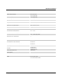
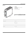
1
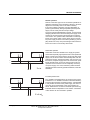
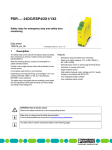
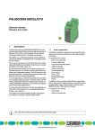
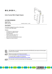
TRIO-PS/1AC/24DC/5
Primary switched power supply, 1-phase,
output current: 5 A
INTERFACE
Data Sheet
102777_02_en
© PHOENIX CONTACT - 06/2007
Description
TRIO POWER is the rail mountable 24 V power supply unit
with basic functions. With an output voltage of 24 V DC and
1-phase and 3-phase versions with 60 W or 960 W, it is particularly suited for use in series production in mechanical engineering. The wide-range input and international certification package allows worldwide implementation.
The high MTBF of 500,000 h stands for high supply reliability.
The devices can be connected in parallel to increase the capacity and redundancy.
The clear LED signaling and the device connection with double terminal block for plus and minus for fast potential distribution are further advantages of this device series. A third
terminal block for minus simplifies the grounding on the secondary side. All power supply units are idle proof and short
circuit proof and provide a regulated and settable output voltage of 22.5 V DC to 29.5 V DC with output currents of 2.5 A,
5 A, 10 A, 20 A or 40 A.
–
–
–
–
Reliable power supply unit even at high ambient temperatures
No load and short circuiting resistance
High dielectric strength
Can be used worldwide in all industrial sectors due to a
wide-range input and an international approval package
DANGER OF EXPLOSION!
Remove an item only when it is not connected to power or if it is located in the non-explosive area.
DANGER
Components with dangerously high voltage and high stored energy are located in the device!
Never carry out work on live parts!
Depending on the ambient temperature and the load, the housing can become very hot!
Make sure you always use the the latest documentation.
It can be downloaded at www.download.phoenixcontact.com.
A conversion table is available on the Internet at
www.download.phoenixcontact.com/general/7000_en_00.pdf.
TRIO-PS/1AC/24DC/5
Table of contents
Description ........................................................................................................................................................................1
Table of contents ............................................................................................................................................................2
Order data .........................................................................................................................................................................3
Technical data..................................................................................................................................................................3
Structure ............................................................................................................................................................................6
Block diagram ..................................................................................................................................................................7
Safety and warning notes ............................................................................................................................................7
Installation .........................................................................................................................................................................8
Installation position .........................................................................................................................................................8
Assembly ...................................................................................................................................................................9
Removing...................................................................................................................................................................9
Connection to various network forms .......................................................................................................................9
Input ..................................................................................................................................................................................10
Protection of the primary side ..................................................................................................................................10
Recommended backup fuse for mains protection ...................................................................................................10
Output ...............................................................................................................................................................................11
Protection of the secondary side .............................................................................................................................11
Signaling ..........................................................................................................................................................................11
Function ...........................................................................................................................................................................12
Output characteristic curve ......................................................................................................................................12
Thermal behavior.....................................................................................................................................................12
Parallel operation.....................................................................................................................................................13
102777_02_en
PHOENIX CONTACT
2
TRIO-PS/1AC/24DC/5
Order data
Description
Type
Order No.
Pcs./Pkt.
Primary switched power supply, 1-phase, output current: 5 A
TRIO-PS/1AC/24DC/5
2866310
1
Technical data
Input data
Input nominal voltage range
100 V AC ... 240 V AC
AC input voltage range
85 V AC ... 264 V AC (derating < 90 V AC: 2.5% per Kelvin)
AC frequency range
45 Hz ... 65 Hz
Current consumption
1.65 A (120 V AC)
0.9 A (230 V AC)
Inrush current limitation
< 15 A
I2t
1.1 A2s
Power failure bypass
> 20 ms (120 V AC)
> 110 ms (230 V AC)
Typical response time
<1s
Power factor (cos phi)
0.72
Protective circuitry
Transient surge protection Varistor
Input fuse, integrated
3.15 A (slow-blow, internal)
Recommended backup fuse for mains protection
6A
10 A
16 A (characteristic B)
Discharge current to PE
< 3.5 mA
Output data
Nominal output voltage
24 V DC ±1%
Setting range of the output voltage
22.5 V DC ... 29.5 V DC
Output current
5 A (0°C ... 55°C)
Derating
Above +55°C: 2.5% per Kelvin
Current limitation
Approx. 10 A (for short circuit)
Max. capacitive load
Unlimited
Control deviation
< 1 % (change in load, static 10% ... 90%)
< 2 % (change in load, dynamic 10% ... 90%)
< 0.1 % (change in input voltage ±10%)
Power loss nominal load max.
18 W
Maximum power dissipation idling
1.1 W
Efficiency
> 89 %
Ascent time
< 2 ms (UOUT (10% ... 90%))
Residual ripple
< 20 mVPP
Peak switching voltages
< 30 mVPP
Connection in parallel
Yes, for redundancy and increased capacity
Connection in series
No
Surge protection against internal surge voltages
Yes, < 35 V DC
Resistance to reverse feed
35 V DC
Signal output DC OK active
Status display
102777_02_en
"DC OK" LED green / UOUT > 21.5 V: LED lights up
PHOENIX CONTACT
3
TRIO-PS/1AC/24DC/5
General data
Insulation voltage input/output
4 kV AC (Type test)
2 kV AC (routine test)
Insulation voltage input / PE
2 kV AC (type test)
2 kV AC (routine test)
Insulation voltage output / PE
500 V DC (type test)
Degree of protection
IP20
Class of protection
I, with PE connection
MTBF
> 500 000 h in acc. with IEC 61709 (SN 29500)
Housing version
Steel sheet, zinc-plated
Side element version
Aluminum
Dimensions W / H / D (state of delivery)
40 mm / 130 mm / 115 mm
Weight
0.6 kg
Ambient conditions
Ambient temperature (operation)
-25 °C ... 70 °C (> 55° C derating)
Ambient temperature (storage/transport)
-40 °C ... 85 °C
Max. permissible relative humidity (operation)
95 % (at 25°C, no condensation)
Vibration (operation)
< 15 Hz, amplitude ±2.5 mm in acc. with IEC 60068-2-6
15 Hz ... 150 Hz, 2.3g, 90 min.
Shock
15g in all directions in acc. with IEC 60068-2-27
Pollution degree in acc. with EN 50178
2
Climatic class
3K3 (in acc. with EN 60721)
Standards
Electrical Equipment for Machinery
EN 60204
Safety transformers for power supply units
EN 61558-2-17
Electrical safety (of information technology equipment)
EN 60950/VDE 0805 (SELV)
EN 61558-2-17
Electronic equipment for use in electrical power installations
EN 50178/VDE 0160 (PELV)
SELV
EN 60950 (SELV)
EN 60204 (PELV)
Safe isolation
DIN VDE 0100-410
DIN VDE 0106-1010
Protection against electric shock
DIN 57100-410
Protection against electric shock, basic requirements for safe isolation in
electrical equipment
DIN VDE 0106-101
Limitation of mains harmonic currents
EN 61000-3-2
Approvals
UL rating
102777_02_en
UL/C-UL Listed UL 508
UL/C-UL Recognized UL 60950
PHOENIX CONTACT
4
TRIO-PS/1AC/24DC/5
Conformance with EMC directive 89/336/EEC
Immunity to interference in acc. with EN 61000-6-2
Discharge of static electricity
Housing
Level 3
Contact discharge
6 kV
Discharge in air
8 kV
Comments
Criterion B
Housing
Level 3
Frequency range
80 MHz ... 3 GHz
Electromagnetic HF field
Field intensity
10 V/m
Comments
Criterion A
Fast transients (burst)
Input
4 kV (level 4 - asymmetrical: conductor to ground)
Output
2 kV (level 3 - asymmetrical: conductor to ground)
Comments
Criterion A
Input/Output
4 kV (level 4 - asymmetrical: conductor to ground)
2 kV (level 4 - symmetrical: conductor to conductor)
Comments
Criterion A
Input/output
Level 3 - asymmetrical
Surge current loads (Surge)
Conducted interference
Frequency range
0.1 MHz ... 80 MHz
Voltage
10 V
Comments
Criterion A
Voltage dips
Input
(mains buffering > 10 ms)
Comments
Criterion B
Emitted interference in acc. with EN 61000-6-3
Radio interference voltage in acc. with EN 55011
EN 55011 (EN 55022) Class B, area of application: Industry and residential
Emitted radio interference in acc. with EN 55011
EN 55011 (EN 55022) Class B, area of application: Industry and residential
102777_02_en
PHOENIX CONTACT
5
TRIO-PS/1AC/24DC/5
Structure
2
4
+
+
–
–
–
Ou
t
24put D
V C
5A
DC
OK
3
1
2
3
4
5
6
AC input
DC output
Potentiometer 22.5 V DC ... 29.5 V DC
"DC OK" LED
DIN rail adapter
Take-up for cable binders
TRIO POWER
5
A
22 dju
.5- st
29
.5V
1
L
Input
Output
N
[mm2]
solid
stranded
0.2 - 2.5 0.2 - 2.5
0.2 - 2.5 0.2 - 2.5
AWG
24 - 14
24 - 14
[Nm]
Torque
0.4 - 0.5
0.4 - 0.5
In
10put A
0-2 C
40
V
6
Input data
Input nominal voltage range
100 V AC ... 240 V AC
AC input voltage range
85 V AC ... 264 V AC (derating < 90 V AC: 2.5% per Kelvin)
AC frequency range
45 Hz ... 65 Hz
Input fuse, integrated
3.15 A (slow-blow, internal)
Recommended backup fuse for mains protection
6A
10 A
16 A (characteristic B)
Type of connection
Screw connection
Stripping length
9 mm
Output data
Nominal output voltage
24 V DC ±1%
Setting range of the output voltage
22.5 V DC ... 29.5 V DC
Output current
5 A (0°C ... 55°C)
Type of connection
Screw connection
Stripping length
9 mm
102777_02_en
PHOENIX CONTACT
6
TRIO-PS/1AC/24DC/5
Block diagram
L
N
PE
Safety and warning notes
The power supply units are built-in devices. The device may only be installed and put into operation by qualified personnel. The corresponding national regulations must be observed.
DANGER OF EXPLOSION!
Remove an item only when it is not connected to power or if it is located in the non-explosive area.
DANGER
Components with dangerously high voltage and high stored energy are located in the device!
Never carry out work on live parts!
Depending on the ambient temperature and the load, the housing can become very hot!
Before startup please ensure:
The mains connection has been carried out by a competent person and protection against electric
shock is guaranteed!
The device can be disconnected outside the power supply unit in accordance with the regulations as
in EN 60950 (e.g. through primary side line protection)!
The ground conductor is connected!
All feed lines are sufficiently protected and dimensioned!
All output lines are dimensioned according to the maximum output current of the device or separately
protected!
Sufficient convection is guaranteed!
102777_02_en
PHOENIX CONTACT
7
TRIO-PS/1AC/24DC/5
Installation
In order to guarantee sufficient convection, we
recommend observing the following minimum
distance to other modules: 5 cm in a vertical direction and 0 cm in a horizontal direction.
+
+
–
–
–
Ou
tp
24 ut D
V C
5A
DC
OK
TRIO POWER
The power supply unit can be snapped onto all
DIN rails in acc. with EN 60715. They must be
mounted horizontally (connecting terminal
blocks top and bottom).
A
22 dju
.5-2 st
9.5
V
L
N
In
10put A
0-2 C
40
V
Installation position
Output DC
24 V 5 A
230
DC OK
Adjust
22.5-29.5V
130
+
+
–
–
–
TRIO POWER
115
50
40
L
N
Input AC
100-240 V
Mounting position: Installation depth 115 mm (+ DIN rail)
102777_02_en
PHOENIX CONTACT
8
TRIO-PS/1AC/24DC/5
A
Assembly
B
Position the module with the DIN rail guide on the upper edge
of the DIN rail, and snap it in with a downward motion.
Removing
Pull the snap lever open with the aid of a screwdriver and
slide the module out at the lower edge of the DIN rail.
B
A
Connection to various network forms
TN-S
TN-C
TT
L
N
PE
L
L
PEN
L
N PE
+
-
iT
N PE
L
+
-
The connection for 100 V AC ... 240 V AC is made using the
L, N and PE screw connections.
The device can be connected to 1-phase AC networks or to
two of the phase conductors of 3-phase networks (TN, TT or
IT networks in acc. with VDE 0100-300/IEC 60364-3) with
nominal voltages of 100 V AC ... 240 V AC.
In the case of input voltages > 300 V AC, the device switches
off for its own safety. After the overvoltage has ceased, the
device starts automatically within a few seconds.
L1
L2
L3
L
N
N PE
L
+
-
N PE
+
-
In order to comply with the UL certification, use
copper cables that are designed for operating
temperatures of > 75°C.
In order to comply with EN 60950/UL 60950,
flexible cables require ferrules. To safely connect a device, the ferrules should have a
length of at least 10 mm. To achieve a reliable
and shockproof connection, strip the connecting ends according to section "Structure".
For operation on two of the phase conductors of a threephase system, an isolating facility for all poles must be provided.
102777_02_en
PHOENIX CONTACT
9
TRIO-PS/1AC/24DC/5
Input
Protection of the primary side
+
+
–
–
–
Ou
tp
24 ut D
V C
5A
DC
OK
A
22 dju
.5-2 st
9.5
V
L
N
TRIO POWER
The device must be installed in acc. with the regulations as
in EN 60950. It must be possible to disconnect the device
using a suitable isolating facility outside the power supply.
The primary side line protection, for example, is suitable. For
device protection, there is an internal fuse. Additional device
protection is not necessary.
Recommended backup fuse for mains protection
Power circuit-breaker 6 A, 10 A or 16 A, characteristic B (or
identical function).
If an internal fuse is triggered, there is most
probably a malfunction in the device. In this
case, the device must be inspected in the
factory!
In
10put A
0-2 C
40
V
102777_02_en
PHOENIX CONTACT
10
TRIO-PS/1AC/24DC/5
Output
+
+
–
–
–
Ou
tp
24 ut D
V C
5A
DC
OK
You can fasten the connection cables to the
housing using cable binders.
Ensure that the cable binders and the connection cables are designed for the surface temperatures that occur in operation.
Make sure that the insulation of the connection
cables is not damaged when tightening the cable binders.
TRIO POWER
Ou
24 tput
V DC
2.5
A
POWER
+
+
–
–
–
Make sure that all output lines are dimensioned according to the maximum output current or are separately protected. The cables on
the secondary side must have sufficiently large
cross sections in order to keep the voltage
drops on the lines as low as possible.
A
22 dju
.5-2 st
9.5
V
L
The connection is made using the "+" and "-" screw connections on the screw connection of the DC output. At the time
of delivery, the output voltage is 24 V DC. The output voltage
can be set on the potentiometer.
N
In
10put A
0-2 C
40
V
Protection of the secondary side
The device is electronically protected against short circuit
and idling. In the event of a malfunction, the output voltage is
limited to 35 V DC.
Signaling
The "DC OK" LED enables evaluation of the function of the power supply directly on site.
State 1
State 2
"DC OK" LED
ON
OFF
Cause
Output voltage > 21.5 V
Output voltage < 21,5 V or no voltage at the output
Meaning
Output voltage and output
current OK
TRIO POWER is in operation, but there is a fault on the side
of the consumer; the current consumption is greater than IN
or the output is short circuited.
TRIO POWER is out of operation because there is no mains
voltage, the fuse on the primary side has been triggered, or
the device is faulty.
102777_02_en
PHOENIX CONTACT
11
TRIO-PS/1AC/24DC/5
Function
UOUT [V]
Output characteristic curve
UN
IN
IOUT [A]
The device functions following the U/I characteristic curve.
Under load, the working point follows this curve. The output
current is limited in the event of a short circuit or overload.
Thereby, the device does not switch off, but rather supplies
a continuous output current.
The secondary voltage is reduced until the short circuit or
overload on the secondary side has been remedied. The U/I
characteristic curve ensures that both heavily capacitive
loads and loads with DC/DC converters in the primary circuit
can be supplied. Downstream fuses are triggered. Selectivity
in the design of your system is guaranteed at all times.
UN = 24 V
IN = 5 A
PN = 120 W
Output current [A]
Thermal behavior
With an ambient temperature of up to +55°C, the device supplies the continuous output current of IN. In the case of ambient temperatures above +55°C, the output current must be
reduced by 2.5% per Kelvin increase in temperature. The device does not switch off at ambient temperatures of +70°C or
thermal overload. The output capacity is reduced as far as
necessary to provide device protection. After it has cooled
down, the output capacity is increased again.
IN
0
0
102777_02_en
20
40
60
Ambient temperature [°C]
PHOENIX CONTACT
12
TRIO-PS/1AC/24DC/5
Parallel operation
Devices of the same type can be connected in parallel to enable both redundancy and an increase in efficiency. No other
alignment is necessary when in the state of delivery.
If the output voltage is adjusted, a uniform distribution of
power is guaranteed by setting all parallel operated power
supply units to exactly the same output voltage.
To ensure symmetrical distribution of power, we recommend
designing all cable connections from the power supply unit to
a busbar of the same length and with the same conductor
cross section. The system makes it advisable to install a protective circuit at the output of each device when more than
two power supply units are connected in parallel (e.g. decoupling diode or DC fuse). This prevents high reverse feed currents in the event of a secondary device fault.
Redundant operation
IN
IN
+ −
+ −
+
−
Σ = IN
+ −
Redundant circuits are suitable for the supply of systems
which make especially high requirements on the operational
safety. If a fault occurs in the primary circuit of the first power
supply unit, the second device automatically takes over the
entire power supply, without interruption, and vice versa. For
this reason, the power supply units to be connected in parallel are dimensioned in such a way that the total current requirement of all consumers can be completely covered by
one power supply unit. 100% redundancy makes external
decoupling diodes necessary (QUINT-DIODE/40, Order No.
2938963)!
Increased performance
IN
IN
+ −
+ −
+
−
+ −
102777_02_en
For n parallel connected devices, the output current can be
increased to n x IN. Parallel connection to increase efficiency
is used for the expansion of existing systems. It is advisable
to use parallel connection if the power supply unit does not
cover the current requirement of the most powerful consumer. Otherwise the consumers should be spread among
individual devices independent of one another. A maximum
of five devices can be connected in parallel!
Σ = 2 x IN
PHOENIX CONTACT GmbH & Co. KG • 32823 Blomberg • Germany
Phone: +49-(0) 5235-3-00 • Fax: +49-(0) 5235-3-4 12 00
www.phoenixcontact.com
13