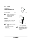
1
PSR-...- 24DC/ESP4/2X1/1X2 Safety relay for emergency stop and safety door monitoring Data sheet 100516_en_05 1 © PHOENIX CONTACT 2013-11-21 Description The safety relay can be used for emergency stop and safety door monitoring as well as in safety circuits according to DIN EN 60204-1. With this switching device, circuits are interrupted in a safety-oriented manner. Control is via a single channel, either with automatic or manual start circuit. A connected reset button is not monitored. Depending on the external wiring, up to category 4, PL e according to EN ISO 13849-1 or SIL CL 3 according to EN 62061 can be achieved. Features – – – – – – – – Emergency stop and safety door monitoring Meets up to safety category 4, PL e (ISO 13849-1), SIL 3 (IEC 61508) Optional plug-in screw or spring-cage terminal blocks Automatic or manual start circuit Single-channel control Safe isolation between mains voltage and 24 V supply voltage in accordance with EN 50178 Two undelayed enable contacts One undelayed signal contact The safety relay is equipped with two enabling current paths and one signaling current path that drop out without delay according to stop category 0. WARNING: Risk of electric shock Observe the safety instructions in the corresponding section! Make sure you always use the latest documentation. It can be downloaded from the product at phoenixcontact.net/products. This data sheet is valid for all products listed on the following pages. PSR-SCP- 24DC/ESP4/2X1/1X2 2 Table of contents 1 Description .............................................................................................................................. 1 2 Table of contents ..................................................................................................................... 2 3 Ordering data .......................................................................................................................... 3 4 Technical data ......................................................................................................................... 3 5 Basic circuit diagram ............................................................................................................... 5 6 Derating................................................................................................................................... 5 7 Load curve - inductive load...................................................................................................... 5 8 Safety notes............................................................................................................................. 6 9 Operating and indication elements .......................................................................................... 7 10 Application examples .............................................................................................................. 8 10.1 Single-channel emergency stop circuit with automatic activation ..................................................... 8 10.2 Single-channel emergency stop circuit with manual activation and monitored contact extension .............. 8 10.3 Single-channel evaluation of a safety controller with automatic activation, suitable for up to SIL 3 ............ 8 11 Proof test ................................................................................................................................. 8 100516_en_05 PHOENIX CONTACT 2 PSR-SCP- 24DC/ESP4/2X1/1X2 3 Ordering data Description Order No. Pcs. / Pkt. Safety relay for SIL 3 high and low-demand applications, also approved ac- PSR-SCP- 24DC/ESP4/2X1/1X2 cording to EN 50156, Germanischer Lloyd, and EN ISO 13849, emergency stop and safety door monitoring, single-channel, 2 enabling current paths, 1 alarm contact, plug-in screw terminal blocks, width: 22.5 mm 2981020 1 Safety relay for SIL 3 high and low-demand applications, also approved ac- PSR-SPP- 24DC/ESP4/2X1/1X2 cording to EN 50156, Germanischer Lloyd, and EN ISO 13849, emergency stop and safety door monitoring, single-channel, 2 enabling current paths, 1 alarm contact, plug-in spring-cage terminal blocks, width: 22.5 mm 2981017 1 Documentation Type Order No. Pcs. / Pkt. User manual, English, for applications for PSR safety relay UM EN SAFETY RELAY APPLICATION 2888712 1 4 Type Technical data Input data Nominal input voltage UN 24 V DC Input voltage range (factor) 0.85 ... 1.1 Typical input current 50 mA DC Typical inrush current <1A Voltage at input/start and feedback circuit 24 V DC Typical response time 60 ms (Automatic/manual start) Typical release time 20 ms Recovery time approx. 1 s Operating voltage display Green LED Status display Green LED Protective circuit Surge protection Suppressor diode, 33 V (A1 - A2, Y2 - A2) Output data Contact type 2 enabling current paths 1 signaling current path (type B according to EN 50205) Contact material AgSnO2, gold-flashed Minimum switching voltage 10 V Maximum switching voltage 250 V AC/DC Limiting continuous current 6 A (N/O contact/N/C contact, high demand) Maximum inrush current 6A Inrush current, minimum 10 mA Interrupting rating (ohmic load) max. 144 W (24 V DC, τ = 0 ms) 200 W (48 V DC, τ = 0 ms) 77 W (110 V DC, τ = 0 ms) 70 W (220 V DC, τ = 0 ms) 1500 VA (250 V AC, τ = 0 ms) Maximum interrupting rating (inductive load) 42 W (24 V DC, τ = 40 ms) 40 W (48 V DC, τ = 40 ms) 35 W (110 V DC, τ = 40 ms) 33 W (220 V DC, τ = 40 ms) Switching capacity min. 0.2 W Mechanical service life Approx. 107 cycles 100516_en_05 PHOENIX CONTACT 3 PSR-SCP- 24DC/ESP4/2X1/1X2 Output data Switching capacity (360/h cycles) 5 A (24 V DC) 5 A (230 V AC) Switching capacity (3600/h cycles) 5 A (24 V (DC13)) 5 A (230 V (AC 15)) Output fuse 6 A gL/gG NEOZED (High demand) 4 A gL/gG NEOZED (Low demand) General data Relay type Electromechanically forcibly guided, dust-proof relay. Nominal operating mode 100% operating factor Degree of protection IP20 Min. degree of protection of inst. location IP54 Mounting position On horizontal and vertical DIN rail Type of housing Polyamide PA non-reinforced yellow Air and creepage distances between the power circuits DIN EN 50178/VDE 0160 Rated surge voltage / insulation 6 kV / Safe isolation, increased insulation Dimensions Screw connection Spring-cage conn. WxHxD 22.5 x 99 x 114.5 mm 22.5 x 112 x 114.5 mm Connection data Screw connection Spring-cage conn. Conductor cross section, solid 0.2 mm² ... 2.5 mm² 0.2 mm² ... 1.5 mm² Conductor cross section, stranded 0.2 mm² ... 2.5 mm² 0.2 mm² ... 1.5 mm² Conductor cross section AWG/kcmil 24 ... 12 24 ... 16 Stripping length 7 mm 8 mm Ambient conditions Ambient temperature (operation) -20 °C ... 55 °C Ambient temperature (storage/transport) -40 °C ... 70 °C Max. permissible relative humidity (operation) 75 % Max. permissible humidity (storage/transport) 75 % Certification / Approvals Approvals Safety data Stop category according to IEC 60204 0 Safety parameters for IEC 61508 - High demand SIL 3 PFHd 1,16 x 10⁻¹⁰ Demand rate < 12 Months Proof test interval 240 Months Duration of use 240 Months Demand rate < 12 Months The specifications apply assuming the following calculation basis dop 365.25 Days hop 24 h tCycle 3600 s 100516_en_05 PHOENIX CONTACT 4 PSR-SCP- 24DC/ESP4/2X1/1X2 Safety parameters for IEC 61508 - Low demand SIL 3 PFDavg 1,24 x 10⁻⁴ Proof test interval 72 Months Duration of use 240 Months Safety characteristic data according to EN ISO 13849 Category 4 Performance level e DCavg 99 % MTTFd 269 Years Duration of use 240 Months Basic circuit diagram Y1 13 23 31 Derating 2 A1 6 ITH [A2] 5 K1 Logic K2 80 70 60 50 40 30 20 10 0 72 32 0 Figure 1 Y2 14 24 Block diagram Designation A1/A2 Y1/Y2 13/14 23/24 31/32 Explanation Safety relay input voltage Feedback circuit Load current path Load current path Confirmation path 10 20 32 Figure 2 7 30 40 45 50 55 60 TA [°C] Derating curve Load curve - inductive load Contact current [A] A2 Contact voltage [V] AC, resistive load DC, resistive load DC, inductive load (L/R 40ms) 100516_en_05 PHOENIX CONTACT 5 PSR-SCP- 24DC/ESP4/2X1/1X2 8 Safety notes WARNING: Risk of electric shock During operation, parts of electrical switching devices carry hazardous voltages. Before working on the switching device, disconnect the power. NOTE: Risk of damage to equipment due to noise emissions When operating relay modules the operator must meet the requirements for noise emission for electrical and electronic equipment (EN 61000-6-4) on the contact side and, if required, take appropriate measures. Please observe the safety regulations of electrical engineering and industrial safety and liability associations! Disregarding these safety regulations may result in death, serious personal injury or damage to equipment. Startup, mounting, modifications, and upgrades should only be carried out by a skilled electrical engineer! WARNING: Risk of automatic machine restart! For emergency stop applications, the machine must be prevented from restarting automatically by a higher-level control system. Protective covers must not be removed when operating electrical switching devices. WARNING: Danger due to faulty devices! The devices may be damaged following an error and correct operation can no longer be ensured. In the event of an error, replace the device immediately. Repairs to the device, especially if the housing must be opened, may only be carried out by the manufacturer or authorized persons. Otherwise the warranty is invalidated. NOTE: Risk of damage to equipment due to incorrect installation For reliable operation, the safety relay must be installed in housing protected from dust and humidity (IP54). Carry out wiring according to the application. Refer to the “Application examples” section for this. 100516_en_05 PHOENIX CONTACT 6 PSR-SCP- 24DC/ESP4/2X1/1X2 9 Operating and indication elements 6 1 Y Y 2 2 A A 2 2 1 K 1 P S P R S R -E S -E P S 4 P 2 4 K 2 14 23 13 30 - 12 AWG 5 - 7 lbs-ins Input: 24V ac/dc Output: 240V ac/24V dc. B300 Pilotduty R300 Pilotduty LISTED IND. CONT. EQ. 32FB 24 23 13 23 31 14 24 31 32 32 Figure 3 14 32 13 23 14 24 1 APPROVALS 24 31 30 - 12 AWG 5 - 7 lbs-ins Input: 24V ac/dc Output: 240V ac/24V dc. B300 Pilotduty R300 Pilotduty LISTED IND. CONT. EQ. 32FB 24 APPROVALS 24 23 13 14 23 32 32 13 14 3 31 32 31 13 2 A Y 1 K K 31 2 2 Y 1 Y 5 A 1 4 7 1 Y A 5 4 6 7 1 PSR-SCP-24DC/ESP4/2X1/1X2 and PSR-SPP-24DC/ESP4/2X1/1X2 Key: Designation 1 2 3 4 5 6 7 100516_en_05 Explanation Metal lock for mounting on the DIN rail COMBICON plug-in screw terminal block COMBICON plug-in spring-cage terminal blocks 31/32 - signaling current path 13/14, 23/24 - undelayed enabling current paths A1/A2 - supply voltage connection Y1/Y2 - feedback circuit PHOENIX CONTACT 7 PSR-SCP- 24DC/ESP4/2X1/1X2 10.3 10 Application examples 10.1 Single-channel emergency stop circuit with automatic activation Single-channel evaluation of a safety controller with automatic activation, suitable for up to SIL 3 Safe PLC K3 K4 OUT 24V DC Emergency stop Y1 Y2 13 23 31 14 24 32 Y1 PSR-ESP 4 L Y2 13 23 31 14 24 32 PSR-ESP 4 A1 A2 A1 A2 24V DC GND K3 GND K4 N Single-channel emergency stop circuit with manual activation and monitored contact extension K3 K4 10.2 Y1 Y2 L L 13 23 31 14 24 32 11 Proof test The PSR-...-24DC/ESP4/2X1/1X2 can be tested by turning off and restart the module. If the module does not start both relays (status LEDs K1 and K2), it must be replaced. PSR-...-24DC/ESP4/2x1/x2 A1 A2 24V DC GND K3 K4 N 100516_en_05 PHOENIX CONTACT GmbH & Co. KG • 32823 Blomberg • Germany phoenixcontact.com 8