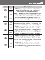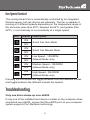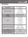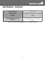
1
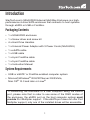
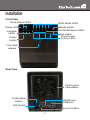
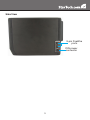
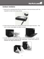
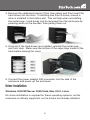
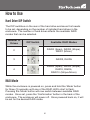
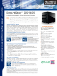
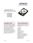
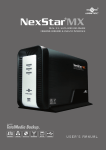
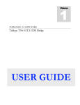
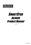
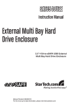
S354UFER
Instruction Manual
External Multi Bay Hard
Drive Enclosure
3.5” 4 Drive eSATA USB FireWire
External Multi Bay Hard Drive
Enclosure with RAID
Manual Revision:08/05/2010
For the most up-to-date information, please visit www.startech.com
FCC Compliance Statement
This equipment has been tested and found to comply with the limits for a Class B digital
device, pursuant to part 15 of the FCC Rules. These limits are designed to provide
reasonable protection against harmful interference in a residential installation. This
equipment generates, uses and can radiate radio frequency energy and, if not installed
and used in accordance with the instructions, may cause harmful interference to radio
communications. However, there is no guarantee that interference will not occur in a
particular installation. If this equipment does cause harmful interference to radio or
television reception, which can be determined by turning the equipment off and on, the
user is encouraged to try to correct the interference by one or more of the following
measures:
• Reorient or relocate the receiving antenna.
• Increase the separation between the equipment and receiver.
• Connect the equipment into an outlet on a circuit different from that to which the receiver
is connected.
• Consult the dealer or an experienced radio/TV technician for help.
Use of Trademarks, Registered Trademarks, and other Protected Names and Symbols
This manual may make reference to trademarks, registered trademarks, and other
protected names and/or symbols of third-party companies not related in any way to
StarTech.com. Where they occur these references are for illustrative purposes only
and do not represent an endorsement of a product or service by StarTech.com, or an
endorsement of the product(s) to which this manual applies by the third-party company
in question. Regardless of any direct acknowledgement elsewhere in the body of
this document, StarTech.com hereby acknowledges that all trademarks, registered
trademarks, service marks, and other protected names and/or symbols contained in this
manual and related documents are the property of their respective holders.
Table of Contents
Introduction...................................................................... 1
Packaging Contents.....................................................................1
System Requirements..................................................................1
Installation........................................................................ 2
Hardware Installation....................................................................4
Driver Installation..........................................................................5
How to Use....................................................................... 6
Hard Drive DIP Switch..................................................................6
RAID Mode...................................................................................6
Drive Status Indicators.................................................................8
eSATA/USB/FireWire Connectivity...............................................8
Fan Speed Control.......................................................................9
Troubleshooting............................................................... 9
Specifications................................................................... 10
Technical Support............................................................ 12
Warranty Information....................................................... 12
i
Introduction
StarTech.com’s S354UFER External Multi Bay Enclosure is a highperformance 4-drive SATA enclosure that connects to host systems
through eSATA or USB or FireWire.
Packaging Contents
• 1 x S354UFER enclosure
• 1 x Screw driver and screw kit
• 4 x Hard Drive Handles
• 1 x Univeral Power Adapter with 3 Power Cords (NA/UK/EU)
• 1 x eSATA cable
• 1 x USB cable
• 1 x 6-pin FireWire cable
• 1 x 9-pin FireWire cable
• 1 x Instruction Manual
System Requirements
• USB or eSATA* or FireWire enabled computer system
• Microsoft Windows® 2000/XP/Server 2003/Vista,
Mac OS® 10.3 and later or Linux®
*If connecting the enclosure to a host computer using the eSATA
port, please note that in order to use some of the RAID modes of
the enclosure, the eSATA port on the host computer system must
provide Port Multiplier support. If the eSATA port does not offer Port
Multiplier support, only one of the installed drives will be accessible.
1
Installation
Front View
Drive Status LEDs
RAID Mode LEDs
Mode switch
Fan Mode/Speed LEDs
Power LED
Interface
LEDs
Fan switch
Drive Power/
Activity LEDs
Power
button
Front Door
release
Rear View
Cooling Fan
(removable)
Confirmation
button
eSATA port
USB port
DIP Switch
6-pin FireWire
2
Side View
9-pin FireWire
ports
DIN power
connector
3
Hardware Installation
1.Secure the included Hard Drive Handles to the hard drives with the
supplied screws and screw driver.
2.Press the front door in to release the latch and open the door. The
door is also removable for easier access.
3.Inside will be a metal drive cage in front of the drive bays. Along
the top of the drive cage are two small tabs. Press them down to
release the cage and remove it.
4
4.Remove the cardboard inserts (if first time setup) and then insert the
hard drives into the slots. If installing less than 4 drives, ensure a
drive is installed in the bottom slot. This will help when reinstalling
the metal cage. Hard drives can be removed from the enclosure by
pressing down on the handles, then pulling them out.
5.Once all of the hard drives are installed, reinstall the metal cage
and front door. Make sure the bottom of the cage stays inside of the
track before closing the cover.
6.Connect the power adapter DIN connector into the side of the
enclosure and power up the enclosure.
Driver Installation
Windows 2000/XP/Server 2003/Vista, Mac OS X, Linux
No driver installation is required for these operating systems, as this
enclosure is natively supported, so the drivers are already installed.
5
How to Use
Hard Drive DIP Switch
The DIP switches on the rear of the hard drive enclosure first needs
to be set, depending on the number of installed hard drives in the
enclosure. The number of hard drives affects the available RAID
modes that can be selected.
Number of
Drives
DIP Switch
Available RAID Modes
2
RAID0 (Span), RAID0 (Stripe),
RAID1 (Mirror)
3
RAID3, RAID5
4
RAID0 (Span), RAID0 (Stripe),
RAID3, RAID5,
RAID10 (Stripe+Mirror)
RAID Mode
While the enclosure is powered on, press and hold the ‘Mode’ button
for three (3) seconds until one of the RAID LED’s start to flash.
Pressing the ‘Mode’ button will now switch between available RAID
modes. Once set, press the ‘Confirmation’ button in the back of the
enclosure. The enclosure will power off. Once powered back on, it will
be set for the desired RAID mode.
6
LED
Status
Description
ON
SPAN: Spanning concatenates multiple hard
drives into a single large disk. Provides no
performance or redundancy benefits.
OFF
ON
OFF
ON
OFF
ON
OFF
ON
OFF
ON
OFF
RAID 0 (Stripe): Striping combines multiple disk
into a single large disk array. The data is split
evenly across each disk simultaneously. Read/
write performance is increased as a result, but
failure of any one disk will make the entire array
unusable.
RAID 1 (Mirror): Mirroring writes the same data
across multiple disk, creating a mirror copy. This
provides redundancy in case one drive fails.
RAID 3: Uses striping to write data to multiple
disks like RAID 0, but reserves one disk for
parity. The single parity disk is a bottle-neck for
writing since every write requires updating the
parity data. Failure of any one disk will still allow
access to the data, until the disk is replaced.
RAID 5: Uses striping to write data to multiple
disks simultaneously and distribute parity
across multiple disks. Failure of any one disk
will still allow access to the data, until the disk is
replaced.
RAID 01 (0+1): Creates a mirrored array, then
stripes each mirrored disk. Combines the
performance of RAID 0 with the redundancy of
RAID 1.
7
Drive Status Indicators
LED
Status
Description
ON
An error has been detected on one or
more hard drive.
OFF
ON
OFF
RAID array is currently rebuilding.
eSATA/USB/FireWire Connectivity
The LED indicators will show which host interface is currently active
on the enclosure. To switch interfaces, shut the enclosure off and
disconnect old cable and then connect the new cable and turn the
enclosure back on. Only one interface can be active at a time, so it is
recommended that only one cable be connected at a time to ensure
the proper interface is chosen.
LED
Status
ON
OFF
ON
OFF
ON
OFF
Description
eSATA connection active
USB connection active
FireWire interface active
8
Fan Speed Control
The cooling Smart Fan is automatically controlled by an integrated
thermal sensor, but can also be set manually. The fan is capable of
running at 3 different speeds depending on the temperature range of
the enclosure (less than 45oC, between 45-54oC, and greater than
55oC), or set manually to run constantly at a single speed.
LED
Status
ON
OFF
ON
OFF
ON
OFF
ON
OFF
ON
OFF
Description
Smart Fan Auto Mode
Smart Fan Manual Mode
Low Speed - 1200RPM
(Manual Mode only)
Medium Speed - 1800RPM
(Manual Mode only)
High Speed - 2500RPM
(Manual Mode only)
Pressing the Fan button will toggle between Auto and Manual modes
and toggle between the different manual fan speeds.
Troubleshooting
Only one drive shows up over eSATA
If only one of the installed hard drives is visible on the computer when
connected over eSATA, ensure that the eSATA port on your computer
system supports Port Multiplier technology.
9
Specifications
USB 2.0, SATA 3.0 Gb/s,
FireWire800
Bus Interface
1 x USB type B
1 x eSATA*
External Connectors
1 x 6-pin FireWire
2 x 9-pin FireWire
1 x DIN power connector
Chipset
PLX OXUFS936QSE
RAID Modes
Span, 0, 1, 3, 5, 0+1
3 x Fan Speed
2 x Fan Mode
3 x Interface Link
LEDs
6 x RAID Mode
1 x Rebuild
1 x Hard Drive Error
1 x Power
USB 2.0: 480 Mbps
eSATA: 3.0 Gbps
Maximum Data Transfer Rate
FireWire400: 400Mbps
FireWire800: 800 Mbps
Fans
1 x 80mm
Number of Hard Drives
Up to 4
Hard Drive Compatibility
3.5” SATA 1.5/3.0 Gbps Hard
Drives, tested up to 2.0TB
10
Specifications - Continued
Power Adapter
12VDC, 5A
Dimensions
215.0mm x 126.0mm x 170.0mm
Weight
1.8kg
Compatible Operating
Systems
Windows 2000/XP/Server 2003/
Vista, Mac OS 10.3 or later,
Linux
* eSATA host controller requires Port Multiplier support
11
Technical Support
StarTech.com’s lifetime technical support is an integral part of our
commitment to provide industry-leading solutions. If you ever need
help with your product, visit www.startech.com/support and access
our comprehensive selection of online tools, documentation, and
downloads.
Warranty Information
This product is backed by a one year warranty.
In addition, StarTech.com warrants its products against defects in
materials and workmanship for the periods noted, following the initial
date of purchase. During this period, the products may be returned
for repair, or replacement with equivalent products at our discretion.
The warranty covers parts and labor costs only. StarTech.com does
not warrant its products from defects or damages arising from misuse,
abuse, alteration, or normal wear and tear.
Limitation of Liability
In no event shall the liability of StarTech.com Ltd. and StarTech.com USA
LLP (or their officers, directors, employees or agents) for any damages
(whether direct or indirect, special, punitive, incidental, consequential, or
otherwise), loss of profits, loss of business, or any pecuniary loss, arising
out of or related to the use of the product exceed the actual price paid
for the product. Some states do not allow the exclusion or limitation of
incidental or consequential damages. If such laws apply, the limitations
or exclusions contained in this statement may not apply to you.
12
StarTech.com has been making “hard-to-find easy” since 1985,
providing high quality solutions to a diverse IT and A/V customer
base that spans many channels, including government, education
and industrial facilities to name just a few. We offer an unmatched
selection of computer parts, cables, A/V products, KVM and Server
Management solutions, serving a worldwide market through our
locations in the United States, Canada, the United Kingdom and
Taiwan.
Visit www.startech.com today for complete information about all
our products and to access exclusive interactive tools such as the
Cable Finder, Parts Finder and the KVM Reference Guide.