1
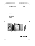
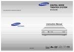
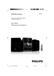
™
Advanced security made easy
plug&playsecurity
™
DVR4-1160™ MPEG
4 Channel Digital Video Recorder
Operating Instructions
Operating Instructions
SW342-LPM
www.swannsecurity.com
SR342-LPM-60010-200609
Before You Begin
FCC Verification:
NOTE: This equipment has been tested and found to comply with the limits for
Class B digital device, pursuant to part 15 of the FCC Rules. These limits are designed to provide reasonable protection against harmful interference in a residential installation. This equipment generates, uses and can radiate radio frequency
energy and, if not installed and used in accordance with the instructions, may
cause harmful interference to radio or television reception, which can be determined by turning the equipment off and on, the user is encouraged to try to
correct the interference by one or more of the following measures:
· Reorient or relocate the receiving antenna
· Increase the separation between the equipment and the receiver
· Connect the equipment into an outlet on a circuit different from that to which
the receiver is connected
· Consult the dealer or an experienced radio/TV technician for help
These devices comply with part 15 of the FCC Rules. Operation is subject to the
following two conditions:
(1) These devices may not cause harmful interference, and
(2) These devices must accept any interference received, including interference
that may cause undesired operation.
IMPORTANT NOTE: Prohibition against eavesdropping
Except for the operations of law enforcement officers conducted under lawful
authority, no person shall use, either directly or indirectly, a device operated pursuant to the provisions of this Part for the purpose of overhearing or recording the
private conversations of others unless such use is authorized by all of the parties
engaging in the conversation.
WARNING: Modifications not approved by the party responsible for compliance
could void user’s authority to operate the equipment.
IMPORTANT SAFETY INSTRUCTIONS:
· Make sure product is fixed correctly and stable if fastened in place
· Do not operate if wires and terminals are exposed
· Do not cover vents on the side or back of the DVR and allow adequate space for
ventilation
Contents
Before You Begin
Contents
Package Contents
DVR Layout
Remote Control
Connecting Cameras to the DVR
Starting the DVR
Main Menu
Hard drive Setup
Setting the Time
Camera Setup
Record Setup
Record Framerate
Video Quality
Record Schedule
Sensor Setup
Motion Detector Setup
System Password
Image Parameters
Miscellaneous Setup
Recording
Playback
Installing DVR Software
Playback
Configuring ActiveX
IP Setup
User Set Up
DxClient
DxClient Layout
Netviewer
HDD Viewer
HDD Viewer (continued)
Installing and changing the HDD
Troubleshooting
Warranty Information
2
3
4
5
6
7
8
9
9
9
10
10
10
11
11
11
12
13
14
14-16
17
18
19
20
21
22
23
24
25
26-28
29
30-32
33
34
35
Package Contents
DVR4-1160™ Unit
Remote Control
Operating Instructions
Easy Setup Guide
Power Adapter with Cable
Software CD
Network cable
USB cable
RCA Video Cable
RCA to BNC adapters X 4
Security Stickers (4 Pack)
If you are missing any of the components above, contact Swann Communications
for assistance.
DVR Layout
Front Panel
10
1
2
3
4
11
12
13
14
1.Rewind - Press to rewind a
recording / press to move cursor left.
2. Pause - Press to pause a recording. -During display mode press
to activate sequence mode.(SEQ.
DWELL TIME must be set).
3. Play - Press to begin playing
most recent recording.
4. Fast foward - Press to fast
forward a recording / press to move
cursor right.
5. Stop - Press to stop a recording.
6. Record - Press to begin recording.
5
Note: will not function if the cameras
are not activated in CAMERA SETUP
AND RECORD SETUP.
7. Hard drive indicator - Lights
when hard drive is active (flashes
when recording, searching etc.)
8. Infra red sensor
9. Power Indicator - Lights on
when DVR powered
10. Channel 1 - Press to view
channel 1.
11. Channel 2 - Press to view
channel 2.
6
7 8 9
15
16 17 18
12. Channel 3 - Press to view
channel 3.
13. Channel 4 - Press to view
channel 4.
14. Quad Mode - Press to view all
channels in quad mode.
15. Up arrow - Move cursor up in
menus.
16. Menu/ESC - Used to enter the
main menu or exit a sub menu.
17. Down - Press to move cursor
down.
18. Select / Edit - Press to select
an option/enter a sub menu.
Back Panel
1
3
4
1.Audio Output
2. Audio Input
3. LAN socket
4. Video Output
2
5
6
7
5. Channel 1,2,3 & 4
6. DC power
7. Grounding Terminal
Remote Control
1
2
3
4
5
1. 0-9 (digit key pad)
- Buttons 1-4 can be used to view channels 1-4 in individual display mode during recording and playback.
- 0-9 can be used for a password.
- 0-9 can be used in NETWORK SETUP to change digits.
Note: cannot be used to set the time or input the time in
time search.
2. ALL
- Press to activate the entire screen for motion detection
in MOTION DETECTOR SETUP.
3 - LEFT arrow
- Move cursor left in menus.
4. REWIND/RWD
- Press to rewind a recording during playback.
5. RECORD
- Press to begin recording.
Note: will not function if the cameras are not activated in
CAMERA SETUP AND RECORD SETUP.
6. MENU
- Used to enter the main menu or exit a sub menu.
7. UP arrow
- Move cursor up in menus.
6
8
7
9
10
11
12
13
14
15
8. SELECT/SEL
-Press to select an option/enter a sub menu.
9. RIGHT arrow
- Press to move cursor right.
10. DOWN arrow
-Press to move cursor down.
11. Mute
- Press to mute audio output.
12. PLAY
- Press to begin playing most recent recording during
playback.
13. FAST FORWARD/FWD
- Press to fast forward a recording.
14. STOP
- Press to stop a recording.
15. Pause
- Press to pause a recording.
-During display mode press to activate sequence mode.
(SEQ. DWELL TIME must be set).
Connecting Cameras to the DVR
Cameras and
accessories optional
1
2
3
4
6
5
1. Connect the power and BNC ends of the security camera to an
extension cable.
2. Connect the DC end on the extension cables to the 4 way power splitter plugs.
3. Connect the camera power supply to the other end of the power splitter.
4. Connect the BNC end of the extension cables to the camera connections on the
back of the DVR unit (CH1, CH2, CH3 & CH4)
5. Connect the DVR power supply plug into the power supply socket on the back of
the DVR.
6. Plug in the camera power adapter and the DVR power adapter to mains power
outlets.
Starting the DVR
Once you have connected the DVR and switched the power on it will begin to boot up.
During boot up you will see the following screens
CHECKING HDD........
MASTER [ST3250310SV]
SLAVE [...... NONE]
V2.6
G-V-MLANG
2009.XX.XX
This third screen will only show on first boot up or after a new hard drive has been installed.
Push SELECT to format the hard drive or MENU to cancel the format and continue with the
start up.
CHECKING HDD........
MASTER [ST3250310SV]
FORMAT HDD CONFIRM
(SELECT) FORMAT / (MENU) CANCEL?
Once the DVR has booted up and you have a camera connected to each channel you should be able to
see a quad screen showing all four displays (below).
1
2
3
1. Displays showing cameras 1 and 3.
2. Audio icon. (in this case audio in active on camera 1)
3. Displays showing cameras 2 and 4.
4. Date stamp. (year:month:day)
5. Time stamp. (hour:minutes:seconds)
4
5
Main Menu
To access the main menu push the MENU button. You can scroll through the sub menus by using the UP &
DOWN buttons on the DVR front panel or the remote control.
The red arrow indicates the sub-menu or option that is currently selected.
See page 4 for DVR functions and page 5 for remote control functions.
Hard drive Setup
Overwrite enabled - Set to ON to enable the hard drive to
overwrite the oldest files when the hard drive is full. When it is
set to OFF the DVR will stop recording once the hard drive has
reached full capacity.
Master HDD size - Total size of the hard drive installed in the DVR
Master HDD used - Amount of disc space and the percentage
currently used up on the hard drive.
HDD format - Select this option to format the hard drive then
push the SELECT button.
Setting the Time
The DVR date and time stamp appear on the bottom right corner of the screen.
Follow these instructions to set/change the DVR date and time.
1. Select the MISCELLANEOUS SETUP option in the main menu.
2. Scroll down to the second option SET TIME and push SELECT.
3. Below the date and time digits you will see a red arrow. Use
the LEFT and RIGHT buttons on the remote or the FWD and
RWD buttons on the front panel to move across.
4. Push the SELECT button to change the data.
Note:
The 0-9 buttons on the remote cannot be used to set the time.
Camera Setup
Camera Setup allows you to choose which channels will be active when the cameras are plugged into the DVR.
When a camera is set to OFF in Camera Setup you will not be able to view the display for that camera. You will also not
be able to record unless the camera is set to ON in Camera Setup.
1. Use the UP, DOWN, LEFT and RIGHT buttons (on the remote)
or the UP, DOWN, RWD (for left) & FWD (for right) buttons to
select the camera you would like to change settings on.
2. Push the SELECT button to change the setting to ON or OFF.
3. To exit the Camera Setup screen push the MENU button.
Record Setup
Record Setup allows you to choose which cameras will be recording when the record button is pushed.
Make sure all cameras are set to ON in the Camera Setup screen to enable Record.
1. Use the UP, DOWN, LEFT and RIGHT buttons (on the remote)
or the UP, DOWN, RWD (for left) & FWD (for right) buttons to
select the camera you would like to change settings on.
2. Push the SELECT button to change the setting to ON or OFF.
3. To exit the Record Setup screen push the MENU button.
Record Framerate
Record Framerate allows you to set each cameras desired framerate.
The maximum no of frames is 50FPS (PAL systems) and 60FPS (NTSC systems) shared between 4 cameras.
1. Use the UP, DOWN, LEFT and RIGHT buttons (on the
remote) or the UP, DOWN, RWD (for left) & FWD (for right)
buttons to select the camera you would like to change settings on.
2. Push the SELECT button to increase the number of FRAMES
PER SECOND and the STOP button to decrease the number
of FPS.
3. To exit the Record Setup screen push the MENU button.
Video Quality
The video quality for all the cameras can be adjusted in the MAIN menu.
1. In the MAIN menu scroll down to VIDEO QUALITY.
2. Push the SELECT button to scroll between LOW, NORMAL,
HIGH and HIGHEST.
3.Push the MAIN menu button once you have selected the quality
level to update the changes.
Record Schedule
Record Schedule allows you to set the DVR to record between specified times or set to record when motion is detected.
The timeline in the Record Schedule screen shows 24 bars representing 24 hours in a day.
1. Use the LEFT and RIGHT buttons (on the remote) or the RWD
(for left) & FWD (for right) buttons to select the hour you would
like to change the settings on.
2. Push the SELECT button to scroll between each bar (hour).
NO RECORD - white bar
NORMAL RECORD - red bar
SENSOR RECORD - white bar with red“S” S
3. To exit the Record Schedule screen push the MENU button.
Sensor Setup
Sensored Record Time
The DVR can be set to continue recording after it has detected motion.
1. Use the UP & DOWN buttons to scroll between each option. Push the
SELECT button to choose between 5, 10, 15, 20, 25 & 30 seconds.
Alarm Time
This is the time the alarm continues to beep after the DVR has detected
motion.
1. With the ALARM TIME option selected push the SELECT button to
choose between 5, 10, 15, 20, 25, 30 seconds, CONTINUOUS (CONT)
& OFF.
Motion Detector Setup
This section allows you to set up motion detection for each camera.
See instructions on MOTION DETECTOR SETUP for setting up the motion detector area.
Motion Detector Setup
1. Select whether you want motion detection ON or OFF. The
motion detector levels range from 1-3 with 1 being the least
sensitive and 3 having the highest sensitivity.
2. With the LEVEL option selected push the SELECT button to
scroll through the motion detector sensitivity levels (1-3).
3. Selecting the AREA option in the MOTION DETECTOR SETUP
screen will take you to a full screen display of the camera you
have selected. Here you can choose the active area for motion
detection for the camera.
The display will have a checkered pattern over the whole image. This means the whole area is currently active for motion detection.
5. Using the arrow keys move the highlighted blinking box to
the area you want to deactivate the motion detection. Once you
selected a box to start on push the SELECT button to deactivate
that box. Continue using the arrows keys to select boxes you
wish to deactivate.
6. If you would like to deactivate the whole area push the STOP
button on either the remote or the DVR control panel; this will
clear all the boxes and leave the entire screen highlighted.
7. To reverse this effect push the ALL button on the remote or
the QUAD MODE button.
figure.1
Blinking highlighted box.
figure.2
Area active for motion detection
When motion detection is active the area will be covered with
a checkered pattern around it.
The highlighted blinking box is the box currently selected. Push
the select button to activate and deactivate this box.
Figure 1 has the checkered pattern over the entire image; motion detection is active.
Figure 2 shows the same image without the checkered pattern; motion detection in
currently not active over the entire image.
When motion detection is inactive the image will have a highlight over the entire screen.
System Password
The DVR includes the option of a six character password. When the password is enabled the DVR will prompt you for it
when you try to:
a. stop a recording
b. reset the menu
c. access the main menu
d. format the hard drive
You will be prompted for the password when attempting to
format the hard drive whether the password is enabled or not.
Enabling and disabling the password
1. Select the MISCELLANEOUS SETUP option in the Main menu.
2. Scroll down to the PASSWORD ENABLE option.
3.Push the SELECT button to set to ON to enable the password
and OFF to disable it.
4.Push the MENU button to go back to the MAIN menu.
Changing the password
1. Select the MISCELLANEOUS SETUP option in the Main menu.
2. Select the first option CHANGE PASSWORD
3.Key in the current password in the first blank field.
4.In the second field key in the new password. Any of the buttons (except for the MENU button) on the remote control or the
DVR front panel can be used to make a password.
5. Confirm the new password by re-entering it in the third blank
field.
The default system password for the DVR is “111111”
Note: the System Password is different to the Admin Password. See User Setup for information on setting up the Admin Password.
Image Parameters
In the IMAGE PARAMETERS screen you can change the picture settings Contrast, Brightness, Hue and Saturation for
each camera. Each setting can be set from 0-100%.
1. In the MISCELLANEOUS SETUP screen scroll down to IMAGE
PARAMETERS.
2. Push the FWD button on the DVR front panel or the RIGHT
button on the remote to choose the camera you would like to
adjust settings for.
3.Push SELECT to enter the settings screen for the selected
channel.
4. Use the UP and DOWN buttons to select between:
CON = Contrast - adjust the brightness ratio of the lightest to
the darkest part of the screen image.
BRI = Brightness - adjust the brightness level of the overall
screen image.
HUE = Hue - adjust the gradation of each colour.
SAT = Saturation - adjust the weight/intensity of each colour.
5. To increase and decrease the settings use the RIGHT and LEFT
buttons on the remote or the FWD and RWD buttons on the
front panel.
Miscellaneous Setup
Hidden Channel
The DVR allows you to hide a channel during monitoring mode. The hidden channel will allow you to record and view in
playback mode; but the display screen for that channel will show a black screen on the live screen.
1. In the Main menu select MISCELLANEOUS SETUP and then
HIDDEN CHANNEL.
2. Push the SELECT button to choose the channel. When OFF is
selected no channel will be hidden.
3. Push the Menu button to go back to the Main menu.
Miscellaneous Setup
Keypad Tones
The beeper sound you hear each time you push a button can be
disabled.
1. In the Main menu select MISCELLANEOUS SETUP and then
KEYPAD TONES.
2. Push the SELECT button to turn ON or OFF.
Sequence Dwell Time
With sequence dwell time activated you can set the time the display shows each channel when the channels are viewed
in individual mode.
1.Select SEQ. DWELL TIME in the MISCELLANEOUS SETUP screen.
2. Push SELECT to choose between 1, 5, 10, 15, 30, 60 seconds and OFF.
3. To activate the sequence function push the PAUSE button when you are in display mode.
4. Push PAUSE again to deactivate the sequence.
Video Loss Time
This function allows you to set a buzzer sound if one of the cameras connected were to be unplugged or if the DVR
could no longer detect that camera. The buzzer will beep three times.
1.Select VIDEO LOSS TIME in the MISCELLANEOUS SETUP screen.
2. Push SELECT to turn ON and OFF.
Audio Port Setup
The DVR allows audio to be recorded on one of the channels. If your cameras do not support audio a seperate microphone can be connected for this.
1. In the Main menu select MISCELLANEOUS SETUP and then
AUDIO PORT SETUP.
2. Select AUDIO PORT 1 - VIDEO CHANNEL and push the SELECT button to select which channel the audio will be recorded
from.
3. The next option allows you to activate the recording. Push the
select button to turn the audio recording ON and OFF.
Miscellaneous Setup (continued)
Language Setup
The DVR can be set to 5 foreign languages. Italian, French, Dutch, Portuguese and Spanish.
1. In the Main menu scroll down to the LANGUAGES option and
push SELECT to change the language.
Note:
If you have changed the language and are having trouble setting it back to English simply push the MAIN menu button until
you see one of the options below:
SELEZIONE LINGUA
CHOIX DE LANGUE
SPRACHE EINSTELLAN
IDIOMA
SELECTO IDIOMA
Then scroll down to the one you see from the list above and push the SELECT button until you get back to English.
Recording
Record Screen
1
2
3
4
5
6
1. Record indicator - When a channel is recording the record indicator will appear beside the channel number.
2. Audio indicator - The audio indicator will appear on the top left corner on the display the audio is aasigned to. See
AUDIO PORT SETUP on page 17 to configure this setting.
Indicates the audio port is assigned to a channel and the audio port is on.
Indicates the audio port is off.
Indicates the audio port is currently recording and audio output is on.
Note:
Pushing the DOWN button on the front panel or the MUTE button on the remote will mute the audio output. The audio
inout can still be recorded while the output is muted.
3. Channel - The number on the top left corner of each display indicates the the channel.
4. Record mode - This indicates which record schedule the DVR is set to.
a. A-REC - Current record schedule is set to NORMAL-RECORD mode.
b. S-REC - Current record schedule is set to SENSOR-RECORD mode
c. N-REC - Current record schedule is set to NO-RECORD mode.
5. Hard drive information - This shows which hard drive is been recorded to and the percentage currently used.
[M] indicates MASTER HDD, [S] indicates SLAVE HDD and *75% indicates 75 percent of the hard drive is full.
6. Date & Time stamp - Current date and time.
Recording and stopping a recording
1. Push the RECORD button in the diplay mode (quad or individual view) to begin recording.
2. Push the STOP button to stop the recording.
Note:
If the password is currently enabled you will be prompted for the password; only the correct password will allow you to
stop the recording.
Playback
Playback Screen
The Search Video screen will display all the recordings currently stored on the hard drive. Playback will automatically
play in quad mode. if you would like to view the footage in individual mode simply push the channel button (1-4)
you’d like to view individually; push the QUAD button on the front panel or the ALL button on the remote. If there is no
recordings stored on the hard drive you will not be able to access the playback screen.
Playing a recording
1. Use the UP and DOWN arrows to select the recording you
would like to playback. The most recent recording will be at the
top of the list.
2. Push the PLAY button to view the recording you have
selected.
Searching the list by time
1. Push the MENU button to scroll up to EVENT; then push the UP or DOWN button to scroll between TIME and EVENT.
2. With the red arrow beside TIME push the SELECT button.
3. You will see the date and time. Use the LEFT and RIGHT arrows on the remote or the RWD and FWD buttons on the
DVR front panel to scroll between each digit for the date and time. (Note: the “20” for the year cannot be changed)
4. Use the SELECT button to change the individual digits for the date and time.
5. Push the MENU button to go back to TIME; then push the UP or DOWN button to scroll between TIME and EVENT.
6. To exit, push the MAIN menu button until you see the display screen.
Installing DVR Software
Installing the DVR software
1. Insert the mini CD into a CD/DVD ROM drive on your computer.
2. If your CD/DVD ROM drive does not auto run the CD; click MY COMPUTER click on the drive the CD is in and double
click on the “DXCLIENT2.7.1-ENG.EXE” file.
3. In the setup window click INSTALL.
Installing DVR Software (continued)
4. Follow the instructions in the setup wizard and click NEXT.
5. The installation is now complete. Tick the checkbox to run the DXCLIENT and click FINISH.
Configuring ActiveX
You may need to change the security settings on your PC to be able to view the DVR remotely. If you are having trouble
viewing your DVR remotely and are getting messages regarding active X controls the following instructions may help.
Changing Security Settings on Internet Explorer
1. Open Internet Explorer.
2. Click TOOLS > INTERNET OPTIONS.
3. In INTERNET OPTIONS click on the SECURITY tab at
the top.
4. Select the INTERNET zone option.
5. Click on the CUSTOM LEVEL button.
6. Find the the following three options and SET them to
PROMPT.
Download signed ActiveX controls.
Download unsigned ActiveX controls.
Initialize and script ActiveX controls not marked as safe
for scripting.
7. After you have changed the settings you wil be asked
to confirm the changes. Click YES.
Set the next two options to ENABLE.
Run ActiveX controls and plug-ins.
Script ActiveX controls marked safe for scripting.
Click OK after you have made the changes.
IP Setup
IP Allocation
DHCP Setup
1. In the NETWORK SETUP sub menu go to IP ALLOCATION
and press SELECT to choose DHCP.
Note: the next five options will now show “0.0.0.0”
2.Push the MENU button to go back to the Main menu.
3. Turn the power off or unplug the power cable from the back
of the DVR to reboot it.
4. Once the DVR has rebooted go back to the NETWORK
SETUP sub menu.
You should now have a complete IP ADDRESS, SUBNET MASK,
GATEWAY and DNS1 ADDRESS.
Static IP Setup - DVR unit
We strongly recommend only advanced users with network
knowledge setup the DVR using a Static IP address.
User Set Up
User Setup
In the USER SETUP screen you can assign the DVR an Admin ID and an Admin Password. These are needed for accessing your DVR remotely. The Admin ID and Password can be up to 14 charaters long.
You can also set a USER ID and PASSWORD. This allows others to view your cameras remotely with restrictions.
The default ADMIN ID is “ADMIN”.
The default PASSWORD is “111111”.
1. Go to the NETWORK SETUP screen and scroll down to USER
SETUP.
2. Select Admin ID and push SELECT.
3. Use the UP and DOWN buttons to scroll through the characters and then push the SELECT button to select that character.
4. Use the LEFT and RIGHT buttons on the remote or the RWD
and FWD buttons on the front panel to move across to the
next character in your password.
5. Repeat steps 3 and 4 to change the ADMIN PASSWORD,
USER ID and USER PASSWORD.
6. Reboot the DVR for the changes to take affect.
Note:
We highly recommend you change the admin password if connecting to a network/
router as this DVR is viewable over the internet and can be easily found using
google search.
Viewing Remotely
Now that you have configured the DVR and your PC you can view your DVR over the internet. The DVR can be viewed
remotely over the internet using the DVR software on the CD included with the DVR or using a web browser (preferably
Internet Explorer).
Using Internet Explorer
1. Open up Internet Explorer. (If you do not have Internet
Explorer you can download it from the Microsoft website
www.microsoft.com.)
2. In the address bar type “HTTP://” followed by your
IP ADDRESS and a colon then your HTTP PORT. eg
“HTTP://192.168.1.100:80” and push ENTER.
See DHCP setup to find your IP address and HTTP port.
3. You will now see a login window. See LOGIN for further
instructions.
http://192.168.1.100:80
DxClient
Opening DxClient PC viewer
1. On your PC click on START > ALL
PROGRAMS (PROGRAMS)
2. Find DXCLIENT and click DXCLIENT in
the DXCLIENT folder.
3. The DxClient program should now be
open with a blank screen. Click on the
large NET button.
Note: the DVR must be connected through a network (using the network cable)
Note: if you are trying to access your DVR from a location outside of your network you will need to
know your PUBLIC IP ADDRESS. If you don’t know your PUBLIC IP ADDRESS go to www.whatismyip.com.
You will need to access this site from a computer which is on the same network as your DVR.
Input the IP address you get from the WHATISMYIP website in the HOST NAME field when logging into
the DxClient or in the address bar when accessing the using Internet Explorer.
Login
3. In the login window type in the following information:
Host name: IP ADDRESS eg. “192.168.1.100”
Host port: HTTP PORT eg. “80”
User name: ADMIN ID eg. “admin” (default)
Password: ADMIN PASSWORD eg. “111111”(default)
192.168.1.100
80
admin
4. Push login. You should now see the camera display on your
PC now.
If you are getting a warning message saying invalid ID or
password; go to the USER SETUP screen to confirm you have
the correct information.
||||||
DxClient Layout
11 12 13
14 15
10
16
17
20
22
18
19
21
23
24
25
26
27
28
29
9
30
8
7
6
5
4
3
2
1
1. Play - Press to begin playing recording
2.Pause - Press to pause recording
3. Stop - Press to stop recording
4. Record - Press to begin recording
5. Rewind - Press to rewind during playback
6. Time Search - Search recording by entering specific
time
7. Convert To Avi - Press to begin stream capturing
8. Capture Image - Press to capture image
9. Video Time Bar - Drag during playack to jump to a
specific time in the recording
10. Toolbar - Double click to maximise screen
11. Pin Down Button - Press to pin DxClient down.
This will keep the DxClient above other windows opened.
(this can also be done by RIGHT clicking and selecting
ALWAYS ON TOP).
12. Minimise - Press to minimise screen
13. Maximise - Press to maximise screen
14. Close - Press to close DxClient.
15. Software Version
16. Left - Move camera left in PTZ
17. Up - Move camera up in PTZ
18. Display Select - Press to select the display you
would like to view
19. Right - Move camera right in PTZ
20. Down - Move camera down in PTZ
21. Zoom In/+ - Press to zoom in, iris in or focus in
(only functions with cameras capable of PTZ)
33
33
32 31
22. PTZ Control - Press to change between ZOOM, IRIS
and FOCUS
23. Zoom Out/- - Press zoom out, iris out or focus out
24. Hdd - USB Connection mode
25. File - Press to select DVR streaming backup file
location
26. Net - Press to open remote viewing login window
27. DVR Settings - Press to view DVR settings
28. Event List - Press to view event list
29. Dxclient Configuration - Press to view System
settings
30. Disconnect - Press to disconnect DxClient
31. Volume Panel
32. Volume Bar - Drag volume bar to increase and
decrease volume.
33. Display - Double click on a display to view that
channel individually. Double clicking on the individual
channel display will take you back to quad mode.
You can also RIGHT click on the display to bring up each
option
Netviewer
The DxClient Netviewer allows you to view, control recording, view playback and control cameras (depending on the
cameras - must have PTZ capabilities).
Note: to view the DVR using the DxClient Netviewer the DVR must be connected to a network (using
the network cable).
DxClient Configuration - Netviewer
1. Click on the DXCLIENT SYSTEM
SETTINGS button.
This will bring up the Netviewer DXCLIENT CONFIGURATION window.
1. CH1, CH2, CH3 or CH4 - Click on the channel you
would like to change the settings on.
2. Camera Setup - Click to turn camera setup ON and
OFF.
3. Record setup - Click to turn record setup ON and
OFF.
5. Sensor Recording - Click to open dropdown options
5, 10, 15, 20, 25 and 30 seconds. HIghlight and click to
make selection.
6. Alarm Sounding - Click to open dropdown options
5, 10, 15, 20, 25, 30 seconds. CONT (continuos) and OFF
HIghlight and click to make selection.
7. EXIT - Click to close DxClient Configuration window.
4. Record Quality - Click to open dropdown options
HIGHEST, HIGH, NORMAL and LOW. Highlight and click
to make selection.
8. Schedule Record Timeline - (--) NO RECORD (S)
Sensor Record (A) Normal Record. Click on the “S”, “A”,
or “--” to change the record setting.
1
2
3
4
5
6
8
7
Netviewer (continued)
Stream Capture
Using the Stream Capture function you can record live footage and then convert it into an AVI file. This enables you to
playback the recording on other meida players such as VLC, DivX or Windows Media player.
1. Click the DVR Settings button.
This will open a HDD viewer DXCLIENT CONFIGURATION
window.
2. Click on AVI STREAM RECORDING FOLDER button to
select the location you want the AVI file to be saved on.
3. Select the folder you want the AVI file to be saved on.
Click OK. Then click SAVE on the DxClient CONFIGURATION window.
Netviewer (continued)
1. Click the BACK UP [AVI] button in the DxClient. This will begin Stream Capturing and open
a mini display.
2. Click the REVIEW AND CONVERT button
when you want the capture to end; below the
mini display shows the time of the current
capture, the maximum time allowed to capture
and below that the number of frames currently
captured.
The maximum capture time is 900 seconds.
3. In this window you can view the footage you
have captured before converting to AVI.
Click where it says PAUSED [CLICK HERE TO
PLAY] to play the captured footage. To pause it
click the same button again.
4. To convert to AVI click the CONVERT TO AVI
button.
5. To view the footage go to the location where
captured footage is saved as an AVI file.
HDD Viewer
DxClient Configuration - HDD Viewer
In this configuration window you can choose where you want the capture images and recording files be saved and
change other miscellaneous settings concerning the DVR when it is connected to a PC using a USB cable..
Note: to view the DVR using the DxClient HDD Viewer the DVR must be connected directly to a PC using
a USB cable.
1. Click the DVR SETTINGS button.
This will bring up HDD viewer DXCLIENT
CONFIGURATION window.
1. BMP CAPTURE SETTING
opens a window so you can choose where the capture images
will be saved when you push the CAPTURE IMAGE button.
2. NO ADDITIONAL INFO ON BMP IMAGE
click to show additional information on captured BMP image.
3. RECORD CONFIGURATION SETTING
opens a window so you can choose where the AVI stream
recordings will be saved when you push the STREAM CAPTURING
button.
4. LANGUAGE SELECT
this cannot be changed; only default language (English) is available on this software version.
clicking this options sets the DxClient to show on top of other
windows on start up.
6. NORMAL PLAYBACK AT STARTUP
click to choose whether the recording plays or is paused on
startup in HDD viewer mode.
7. HIDE CHANNEL FRAMERATE ON SCREEN
click to choose to hide or show the framerate during HDD viewer
mode.
8. SAVE
click to SAVE changes.
9. CANCEL
Click to cancel changes.
5. NORMAL WINDOW AT STARTUP
1
2
3
4
10
5
6
7
8
9
HDD Viewer (continued)
Backup
The DVR allows you to backup all your recordings onto your hard drive. The backup format is a MCG file which can be
played back on the DxClient; you can select where you would like the MCG file saved. (it only allows you to select the
drive you would like to save the MCG file in).
Note: make sure you have the DVR connected to your PC using the USB cable. The network cable must
not be connected for this to function.
1. Click the BACK UP [AVI] button in the DxClient. This will open
the RECORD CONFIGURATION window.
2. Click on the MCG BACKUP button at the bottom of the
window.
3. BACKUP STARTS - Select the date and time from when you
want the backup to begin.
4. BACKUP ENDS - Select the date and time when you want the
backup to end.
5. DRIVE - Select the hard drive you would like the MCG file to
be saved in.
6. FILENAME - Name your back up file. The default name is
DUMP.MCG. Remember to include the MCG file extension if you
change the filename, otherwise the DxClient will not be able to
find the backup file.
7. Click OK. Backup will now begin.
HDD Viewer (continued)
Viewing Backup File
Once you have selected the drive you want the backup files to be saved on and have completed the backup you can
view the file on the DxClient.
1. Click on the large FILE button on the right panel of the
DxClient.
Note: viewing the recordings can be done with
the DVR connected to a PC using either USB or
network cable.
2. Select the drive you chose to save the backup file on.
3. Search for the MCG file on that drive and click the MCG
file.
4. Click the OPEN button.
5. The backup file will now begin to play in the DxClient.
Event Record List
With the DxClient software you can browse through all the recordings remotely and play them back on your PC.
1. Click the EVENT LIST button on the left of the control
panel on the DXClient software.
2. The EVENT LIST window will now be open.
Use the arrows on the sidebar to scroll the list.
3. Select the recording you would like to view and click it
so that it is highlighted.
4. Click the PLAYBACK button on the bottom left of the
Event List window.
5. The video will now begin playing. Push STOP to end
playback.
HDD Viewer (continued)
Search Time
You can also search the recordings by going to a specific time and date. If you have a certain date and time you would
like to playback footage from; you can use the Search Time function to do this.
1. Click on the Search Time button.
Note: the DVR must be in Netviewer mode (connected to a
PC using a network cable) for the Search Time button to be
active.
2. Input the date and time you would like to see footage
from.
The DVR will playback your search from the time you input.
If there is no recording for the time you input nothing will
happen.
Installing and changing the HDD
Note: the following instructions are for installing or changing the hard drive. If
your DVR already has a hard drive pre-installed disregard these steps.
1. Ensure the DVR is unplugged and removed from mains power.
2. Locate and remove the 5 screws 2 on each
side of the DVR and one on the back at the
top of the case.
3. Pull up the top case of the DVR.
side of DVR (2 more screws on otherside of DVR)
back of DVR
Remove
4. Locate the 4 screws holding down the
hard drive stand.
5. Push the metal clip on the SATA cable
(single RED or ORANGE cable) to unplug
the cable from the hard drive. Unplug the
power cable (2 BLACK 1 YELLOW and
1 RED cable) from the back of the Hard
Drive.
SATA Cable
Remove
Power Cable
Now remove the 4 screws attaching the stand
pieces to the hard drive.
Remove
6.
7.
8.
9.
Replace the Hard Drive and plug in the SATA and the power cable as shown in step 5.
Screw in the hard drive to case as in step 4.
Replace the top of the case.
Screw in the remaining screws to the sides and back of the DVR as in step 2.
Troubleshooting
Problem: My monitor is not showing any display/picture.
Solution: Make sure you have connected the VIDEO OUTPUT to a VIDEO INPUT on the back of
your TV/monitor
Problem: My DVR does not switch on.
Solution: Make sure you have plugged in the power supply (12V 3A) to the DVR and into the
wall socket.
Problem: My display is showing “NO HARD DISK” when i press record.
Solution: If you have recently changed the hard drive in your DVR unit make sure it is plugged
in properly; otherwise the hard drive may be faulty. Try connecting another (working) hard drive
to the DVR; if this still doesn’t work then the DVR maybe faulty. We suggest you return the DVR
to the retailer.
Problem: I am not getting picture on any of my displays.
Solution: Make sure the cameras are connected properly to the DVR and the power supply (12V
1A). Check that the cables are not faulty by connecting the cameras directly to the DVR or to a
TV (if you have the proper adapters).
Problem: One of the displays is not showing on my screen.
Solution: Make sure all cameras are set to ON in CAMERA SETUP. Make sure you don’t have the
HIDDEN CHANNEL function (in MISCELLANEOUS SETUP) on for one of the cameras .
Problem: I cannot login to my DVR remotely using the DxClient software or the Internet Explorer browser.
Solution: Make sure you have configured the IP, ActiveX and USER SETUP correctly. Remember
the SYSTEM PASSWORD is different to the ADMIN PASSWORD. The ADMIN PASSWORD is used
to login to the DVR remotely.
Problem: I cannot perform a backup.
Solution: Make sure the DVR is connected to a PC using the USB cable. Make sure the USB
cable is connected properly to the DVR and PC. Avoid having both the network cable and USB
cable connected to the DVR at the same time.
Installing and changing the HDD
DVR4-1160
Video
Video Format
Video Input
Video Output
Display Resolution
Display Frame Rate
NTSC or PAL
4CH Composite
1CH Composite
NTSC: 720 x 480
PAL:
720 x 576
NTSC: 120fps (4 x 30fps)
PAL:
100fps (4 x 25fps)
Audio
Audio Input
Audio Output
1 RCA Input
1 RCA Output
Recording
Compression Format
Recording Resolution
Recording Frame Rate
Recording Modes
Multiplex Operation
HDD Interface
Hard Drive Support
MPEG4
NTSC: 720 x 240
PAL:
720 x 288
NTSC: 60fps (4 x 15fps)
PAL:
50fps (4 x 12fps)
Manual / Schedule / Motion
Triplex
SATA
Up to 1TB
Network
LAN Connection
Network Interface
Network Type
Protocol
DDNS Supported
Remote Operation
Yes
RJ45
Static, DHCP, PPOE
TCP/IP
Yes
Yes
General
Operating Power
Dimensions
Weight
Backup Method
Mouse Support
Remote Control
Remote Battery Type
DC 12V
9.8” x 8.7” x 1.6” / 250mm x 220mm x 40mm
3.3lbs / 1.5 Kg
USB to PC
No
Yes
2 x AAA
Helpdesk / Technical Support Details
Swann Technical Support
All Countries E-mail: [email protected]
Telephone Helpdesk
USA toll free
1-800-627-2799
(Su, 2pm-10pm US PT)
(M-Th, 6am-10pm US PT)
(F 6am-2pm US PT)
USA Exchange & Repairs
1-800-627-2799 (Option 1)
(M-F, 9am-5pm US PT)
AUSTRALIA toll free
1300 138 324
(M 9am-5pm AUS ET)
(Tu-F 1am-5pm AUS ET)
(Sa 1am-9am AUS ET)
NEW ZEALAND toll free
0800 479 266
INTERNATIONAL
+61 3 8412 4610
See http://www.worldtimeserver.com for information on time zones and the
current time in Melbourne, Australia compared to your local time.
Warranty Information
Swann Communications USA Inc.
12636 Clark Street
Santa Fe Springs CA 90670
USA
Swann Communications PTY. LTD.
Building 4, 650 Church Street,
Richmond, Victoria 3121
Australia
Swann Communications warrants this product against defects in workmanship and material
for a period of one (1) year from it’s original purchase date. You must present your receipt
as proof of date of purchase for warranty validation. Any unit which proves defective during
the stated period will be repaired without charge for parts or labour or replaced at the sole
discretion of Swann. The end user is responsible for all freight charges incurred to send the
product to Swann’s repair centres. The end user is responsible for all shipping costs incurred
when shipping from and to any country other than the country of origin.
The warranty does not cover any incidental, accidental or consequential damages arising
from the use of or the inability to use this product. Any costs associated with the fitting or
removal of this product by a tradesman or other person or any other costs associated with
its use are the responsibility of the end user. This warranty applies to the original purchaser
of the product only and is not transferable to any third party. Unauthorized end user or
third party modifications to any component or evidence of misuse or abuse of the device will
render all warranties void.
By law some countries do not allow limitations on certain exclusions in this warranty. Where
applicable by local laws, regulations and legal rights will take precedence.
Advanced
security made easy™
© Swann
Communications
2009