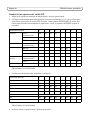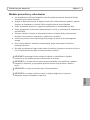
1
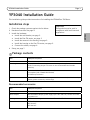
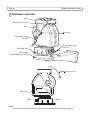
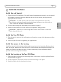
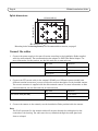
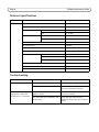
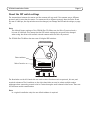
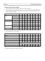
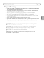
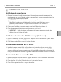
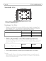
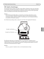
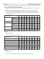
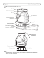
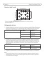
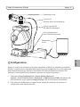
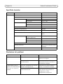
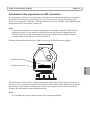
INSTALLATION GUIDE
ENGLISH
YP3040 Pan-Tilt Motor
FRANÇAIS
DEUTSCH
ITALIANO
ESPAÑOL
About this Document
This document includes instructions for installing the
YP3040 Pan-Tilt Motor.
Legal Considerations
Video and audio surveillance can be prohibited by laws
that vary from country to country. Check the laws in
your local region before using this product for
surveillance purposes.
Electromagnetic Compatibility (EMC)
If use of this equipment causes harmful interference to
radio or television reception, which can be determined
by turning the equipment off an on, the user is
encouraged to try to correct the interference by one of
more of the following measures: Re-orient or relocate
the receiving antenna. Increase the separation between
the equipment and receiver. Connect the equipment to
an outlet on a different circuit to the receiver. Consult
your dealer or an experienced radio/TV technician for
help. Shielded (STP) network cables must be used with
this unit to ensure compliance with EMC standards.
USA - This equipment has been tested and found to
comply with the limits for a Class A digital device,
pursuant to Part 15 of the FCC rules. These limits are
designed to provide reasonable protection against
harmful interference when the equipment is operated in
a commercial environment. This equipment generates,
uses and can radiate radion frequency energy and, if not
installed and used in accordance with the instrucion
manual, may cause harmful interference to radion
commmunications. Operation of this equipment in a
residential area is likely to cause interference, in which
case the user will be required to correct the interference
at his own expense.
Canada - This Class A digital apparatus complies with
Canadian ICES-003.
Europe This digital equipment fulfills the
requirements for radiated emission according to limit A
of EN55022/1998, and the requirements for immunity
according to EN55024/1998 residential, commercial,
and industry.
Warning! This is a Class A product. In a domestic
environment this product may cause radio interference,
in which case the user may be required to take adequate
measures.
Japan - This is a class A product based on the standard
of the Volontary Control Council for Interference by
Information Technology Equipment VCCI. If this
equipment is used in a domestic environment, radio
distrubance may arise.
Australia - This electronic device meets the
requirements of the Radio communications
(Electromagnetic Compatibility) Standard AS/NZS
CISPR22:2002. This is a class A product In a domestic
environment this product may cause radio interference
in which case the user may be required to take adequate
measures.
Korea - This equipment has obtained EMC registration
for business use (Class A), and is intended for use in
commercial environments.
Equipment Modifications
This equipment must be installed and used in strict
accordance with the instructions given in the user
documentation. This equipment contains no
user-serviceable components. Unauthorized equipment
changes or modifications will invalidate all applicable
regulatory certifications and approvals.
Liability
Every care has been taken in the preparation of this
document. Please inform your local Axis office of any
inaccuracies or omissions. Axis Communications AB
cannot be held responsible for any technical or
typographical errors and reserves the right to make
changes to the product and documentation without
prior notice. Axis Communications AB makes no
warranty of any kind with regard to the material
contained within this document, including, but not
limited to, the implied warranties of merchantability
and fitness for a particular purpose. Axis
Communications AB shall not be liable nor responsible
for incidental or consequential damages in connection
with the furnishing, performance or use of this material.
RoHS
This product complies with both the European
RoHS directive, 2002/95/EC, and the Chinese
RoHS regulations, ACPEIP.
WEEE Directive
The European Union has enacted a Directive
2002/96/EC on Waste Electrical and Electronic
Equipment (WEEE Directive). This directive is
applicable in the European Union member
states.
The WEEE marking on this product (see right) or its
documentation indicates that the product must not be
disposed of together with household waste. To prevent
possible harm to human health and/or the environment,
the product must be disposed of in an approved and
environmentally safe recycling process. For further
information on how to dispose of this product correctly,
contact the product supplier, or the local authority
responsible for waste disposal in your area.
Business users should contact the product supplier for
information on how to dispose of this product correctly.
This product should not be mixed with other commercial
waste.
Support
Should you require any technical assistance, please
contact your Axis reseller. If your questions cannot be
answered immediately, your reseller will forward your
queries through the appropriate channels to ensure a
rapid response. If you are connected to the Internet, you
can:
• download user documentation
• find answers to resolved problems in the FAQ database.
Search by product, category, or phrases
• report problems to Axis support by logging in to your
private support area.
YP3040 Installation Guide
Page 3
YP3040 Installation Guide
This installation guide provides instructions for installing the YP3040 Pan-Tilt Motor.
Installation steps
Important!
This product must be used in
compliance with local laws and
regulations.
Package contents
Item
Models/variants/notes
Pan-tilt motor
YP3040
Mounting kit
2 screws M5x10 for mounting the camera housing on the splint
4 bolts for mounting the pan-tilt motor on the recommended wall bracket
1 allen key
Printed materials
YP3040 Installation Guide (this document)
Drill template (with YP3040 Wall Bracket)
Axis Warranty Document
Optional accessories
See www.axis.com for information on product documentation, installation tools,
cameras, power accessories, and housings
Recommended accessories
Item
Models/variants/notes
Wall bracket
YP3040 Wall Bracket for YP3040 Pan-Tilt Motor
Mains adaptor
AXIS PS24 Mains Adaptor, power supply input 100—230 V AC, suitable for indoor
and outdoor use
Housing
AXIS T92A20 Housing to be mounted on YP3040 Pan-Tilt Motor
Network cameras
AXIS P13-E series
AXIS Q1755-E
AXIS Q1910-E
ENGLISH
1. Check the package contents against the list below.
2. Hardware overview. See page 4.
3. Install the hardware.
• Install the wall bracket, see page 5.
• Install the Pan-Tilt motor, see page 5.
• Install the camera in the housing, see page 5.
• Install the housing on the Pan-Tilt motor, see page 5.
• Connect the cables, see page 6.
4. Setup, see page 7.
Page 4
YP3040 Installation Guide
Hardware overview
Splint
Mounting screw (4x)
Brace
Brace axis
PTZ control cable
RS-485
Power supply cable
24 V AC
Mounting base
Wall bracket
(recommended accessory)
Direction of tilt
Side panel
Rear
Front
Note:
For functions behind the side panel, refer to About the DIP switch settings, on page 9
YP3040 Installation Guide
Page 5
Install the hardware
Install the wall bracket
1. Prepare the wall for installation of the wall bracket (recommended accessory), use the supplied
drill template to position the holes. Make sure to use drill bits, screws, and plugs that are
appropriate for the material.
IMPORTANT! - To avoid collision, make sure there is enough clearance around the
pan-tilt motor and camera/camera housing (minimum clearance to the ceiling is 60 cm
or 24 in. from the top edge of the wall bracket).
2. Pull the cables through the wall bracket, see illustration on page 7.
3. Attach the wall bracket to the wall with the round platform facing upwards.
!
IMPORTANT! - Make sure to leave enough slack to allow for the cables to twist and
bend along with the unit.
Install the Pan-Tilt Motor
1. Place the pan-tilt motor on the wall bracket, see illustration on page 4 for alignment and direction of tilt.
2. Secure the pan-tilt motor by tightening the supplied bolts.
Install the camera in the housing
Install the camera in the housing according to the instructions in the Installation Guide provided
with the housing. Make sure to allow for the PTZ control cable to pass through the housing to the
camera, see Connect the cables, on page 6. For more information, see the Installation Guides
provided with the housing and the camera.
Install the housing on the Pan-Tilt Motor
1. Detach the splint by removing the mounting screws on the brace, using the supplied allen key.
See illustration on page 4.
2. Use the supplied 2 countersunk screws to mount the housing on the splint.
3. Attach the splint with the housing to the brace.
ENGLISH
!
Page 6
YP3040 Installation Guide
Splint dimensions
70 mm (3.9 in.)
100 mm (3.9 in.)
122 mm (4.8 in.)
Ø 6 mm (0.2 in.)
Mounting holes for housing/camera, see Recommended accessories, on page 3
Connect the cables
1. Connect the power supply to the pan-tilt motor according to the Installation Guide supplied
with the mains adaptor. The recommended mains adaptor is AXIS PS24 Mains Adaptor. For
more information on this product, see the Axis web site at www.axis.com
Power supply cable 24 V AC
Wire color
Connect to
Red
24 V AC on power supply
Red
24 V AC on power supply
Yellow/green
GND
2. Connect the PTZ control cable to the camera’s RS-485 port. Different camera models have
different terminal connectors, be sure to follow the correct description for the installed camera.
The correct connector is supplied with the Axis network camera. For more information on Axis
network cameras, see the Axis web site at www.axis.com
PTZ control cable (RS-485)
Wire color
Connect to
Red
A+ on camera
Blue
B- on camera
3. Connect the camera to the network, see the Installation Guide provided with the camera.
Note:
The RJ-45 connector for the network cable will not pass through the cable gland on the
underside of the housing. The cable must be cut, threaded through the cable gland and
then re-crimped.
YP3040 Installation Guide
Page 7
Network camera
Network cable
(Ethernet RJ-45 to camera)
PTZ control cable
(RS-485 to camera)
Mains
adaptor
Setup
When you install a compatible Axis network camera on the YP3040 Pan-Tilt Motor, the controls will
be available from the Live View page in the camera’s web pages after enabling the PTZ functionality
in Setup tools. Follow these instructions to enable PTZ functionality in the camera:
1. Go to Setup > System Options > Ports & Devices > COM Port in the camera’s web pages, and
set Usage to Pan Tilt.
2. Refer to the User’s Manual supplied with your product for instructions on how to configure the
PTZ settings.
ENGLISH
Power supply cable
(24 V AC from mains adaptor)
Page 8
YP3040 Installation Guide
Technical specifications
Unit
Function
Description
YP3040
Input voltage
24 V AC 50/60 Hz
Power consumption
30 VA
Movement range
Movement speed
Pan
0° to 355°
Tilt
10° to -80°
Pan
7.5°/s
Tilt
6°/s
Protocol (default)
Pelco-D
Bit rate (default)
2400 bps
Address (default)
1
Operating temperature
-20°C to 65°C (-4°F to 149°F)
Load
Torque (brace axis, see page 4) 1.5 N m (1.1 ft. lb)
Load type
Maximum load
Weight
Top load
10 kg (22 lb)
4.2 kg (9 lb)
Protection class
IP66 (indoor and outdoor use)
Construction
Aluminum alloy
Troubleshooting
Problem
YP3040 does not move
Probable cause
Remedy
No power applied
Check that power supply is connected
Faulty connection in power supply
Check that power supply cable is
intact and connected correctly
YP3040 moves when power is Faulty RS-485 cable connection to
applied, but is otherwise
network camera
unresponsive to commands
PTZ functionality not enabled in network camera
Check that RS-485 cable is intact and
connected correctly
Check that PTZ functionality is
enabled in Setup tools, see Setup, on
page 7
YP3040 Installation Guide
Page 9
About the DIP switch settings
The transmission between the motor and the camera will not work if the camera uses a different
protocol and bit rate than the motor. For cameras with a different protocol than the Pelco-D and
bit rate of 2400 bps, the dip switches must be changed, see Change the DIP switch settings, on page
10.
The YP3040 Pan-Tilt Motor has two sets of 8 digital DIP switches.
Select address
Select function
The 8 switches on the left-hand side are used to select functions such as protocol, bit rate, and
terminal resistance. The 8 switches on the right-hand side are used to select multiple unique
addresses when connecting several units in a series through a multi-channel video server. There are
255 different switch combinations.
Note:
In a typical installation only the one default address is required.
ENGLISH
Note:
The default factory settings of the YP3040 Pan-Tilt Motor are the Pelco-D protocol and a
bit rate of 2400 bps. This means that the DIP switch settings do not need to be changed
when using the motor with an Axis network camera with the Pelco-D protocol.
Page 10
YP3040 Installation Guide
Change the DIP switch settings
1. Loosen the 4 side panel mounting screws and remove the side panel.
2. Set the 8 switches to select functions. Switches 1, 2, 3, and 4 are used to select the PTZ control
protocol. Switch 7 is always OFF. Switch 8 is used to connect a terminal resistance of 120 Ω,
switch to ON when required.
Select functions
Protocol
Bit rate
Terminal resistance
Pelco-D (default)
1
2
3
4
ON
ON
OFF
OFF
Pelco-P
OFF
ON
OFF
OFF
AD/AB
OFF
OFF
ON
OFF
5
6
2400 bps (default)
OFF
OFF
4800 bps
ON
OFF
9600 bps
OFF
ON
19200 bps
ON
ON
7
8
OFF (default)
OFF
120 Ω
ON
OFF
3. Set the 8 switches to select address.
Select address
1
2
3
4
5
6
7
8
1 (default)
ON
OFF
OFF
OFF
OFF
OFF
OFF
OFF
2
OFF
ON
OFF
OFF
OFF
OFF
OFF
OFF
3
OFF
OFF
ON
OFF
OFF
OFF
OFF
OFF
4
OFF
OFF
OFF
ON
OFF
OFF
OFF
OFF
5
OFF
OFF
OFF
OFF
ON
OFF
OFF
OFF
...
.............................
254
OFF
ON
ON
ON
ON
ON
ON
ON
255
ON
ON
ON
ON
ON
ON
ON
ON
4. Replace the side panel and tighten the screws.
YP3040 Installation Guide
Page 11
Safeguards & warnings
•
•
•
•
•
!
!
!
!
IMPORTANT! - Keep the motor clear of unidentified objects or corrosive liquids since
that may cause the motor to short circuit.
IMPORTANT! - Do not install the motor on unstable brackets, unstable or vibrating
surfaces or walls, since this may cause injury to people or damage the motor.
IMPORTANT! - Do not touch the motor during operation.
IMPORTANT! - Do not install or operate the motor on dangerous sites that store
inflammable or explosive objects.
ENGLISH
•
•
•
Please read through this Installation Guide carefully prior to installing your product. Keep
the Installation Guide for further reference.
Turn off the power before cleaning the motor. Do not use chemicals, caustic agents, or
aerosol cleaners. Use a damp cloth for cleaning.
Only use accessories and replacement parts provided or recommended by Axis.
Use 24 V AC power supply only, AXIS PS24 Mains Adaptor is recommended.
Protect the power supply cable from any damage; pay special attention to plug fittings,
extensions and outputs.
Install a surge protector to protect the motor from power surges.
Avoid using excessively long installation wires in order to prevent fire or electrical shocks.
Do not remove the covers or repair the product by yourself, contact Axis or your Axis
reseller for service matters.
YP3040 Guide d'installation
Page 13
YP3040 Guide d’installation
Ce guide d’installation vous explique comment installer votre YP3040 Moteur Pan-Tilt.
Procédure d’installation
Contenu de l’emballage
Article
Modèles/variantes/remarques
Moteur Pan-Tilt
YP3040
Kit de montage
2 vis M5x10 pour fixer le boîtier de la caméra sur l’éclisse
4 boulons pour fixer le moteur Pan-Tilt sur le support mural recommandé
1 clé Allen
Documentation imprimée
Guide d’installation de l’YP3040 (le présent document)
Gabarit de perçage (avec support mural YP3040)
Document de garantie d’Axis
Accessoires en option
Consultez le site www.axis.com pour plus d’informations sur la documentation, les outils d’installation, les caméras, les accessoires d’alimentation et
les boîtiers
Accessoires recommandés
Article
Modèles/variantes/remarques
Support mural
Support mural pour YP3040 Moteur Pan-Tilt
Adaptateur secteur
Adaptateur secteur de l'AXIS PS24, entrée bloc d’alimentation 100—230V CA
(utilisation intérieure et extérieure)
Boîtier
Boîtier AXIS T92A20 à fixer sur votre YP3040 Moteur Pan-Tilt
Caméras réseau
AXIS P13-E series
AXIS Q1755-E
AXIS Q1910-E
FRANÇAIS
Important !
Ce produit doit être utilisé
1. Vérification du contenu de l’emballage par rapport à la
conformément aux lois et
liste ci-dessous.
dispositions locales en vigueur.
2. Vue d’ensemble du matériel. Reportez-vous à la page 14.
3. Installation du matériel.
• Installation du support mural, reportez-vous à la page 15.
• Installation du moteur Pan-Tilt (Panoramique/Inclinaison), reportez-vous à la page 15.
• Installation de la caméra dans le boîtier, reportez-vous à la page 15.
• Fixation du boîtier au moteur Pan-Tilt, reportez-vous à la page 15.
• Branchement des câbles, reportez-vous à la page 16.
4. Configuration, reportez-vous à la page 17.
Page 14
YP3040 Guide d'installation
Description du matériel
Éclisse
Vis de fixation (4x)
Support de renfort
Axe du support
de renfort
Câble de contrôle PTZ
RS-485
Câble du bloc
d’alimentation
24 V CA
Base de fixation
Support mural
(accessoire recommandé)
Orientation
d’inclinaison
Panneau latéral
Arrière
Avant
Remarque :
Pour plus d’informations sur les fonctions derrière le panneau latéral, reportez-vous à la
section À propos des paramètres du commutateur DIP, page 19
YP3040 Guide d'installation
Page 15
Installation du matériel
Installation du support mural
1. Préparez le mur pour installer le support mural (accessoire recommandé) en marquant les
emplacements des trous à l’aide du modèle de perçage fourni. Assurez-vous que les forets, les
vis et les fiches sont adaptés au matériau.
!
IMPORTANT ! - Pour éviter des chocs, assurez-vous que l’espace entre le moteur
Pan-Tilt et la caméra ou le boîtier de celle-ci est bien dégagé (la distance entre le
plafond et le bord supérieur du support mural doit être de 60 cm ou 24 po au
minimum).
2. Faites passer les câbles à travers le support mural, voir l’illustration à la page 16.
3. Fixez le support mural (plateforme circulaire tournée vers le haut).
IMPORTANT ! - Veillez à maintenir suffisamment de jeu pour permettre la torsion des
câbles et leur repli le long de l'unité.
Installation du moteur Pan-Tilt (Panoramique/Inclinaison)
1. Placez le moteur Pan-Tilt sur le support mural. Reportez-vous à l'illustration à la page 14 pour
l'alignement et la direction de l'inclinaison.
2. Fixez le moteur Pan-Tilt en serrant les boulons fournis.
Installation de la caméra dans le boîtier
1. Installez la caméra dans le boîtier conformément aux instructions décrites dans le guide
d’installation fourni avec le boîtier. Veillez à pouvoir faire passer le câble de contrôle PTZ à
travers le boîtier vers la caméra, reportez-vous à la section Branchement des câbles, page 16.
Pour plus d’informations, consultez les guides d’installation fournis avec le boîtier et la caméra.
Fixation du boîtier au moteur Pan-Tilt
1. Retirez l’éclisse en desserrant les vis du support de renfort à l’aide de la clé Allen fournie. Voir
l’illustration à la page 14.
2. Fixez le boîtier sur l’éclisse à l’aide des deux vis à tête fraisée fournies.
3. Fixez l’éclisse portant le boîtier au support de renfort.
FRANÇAIS
!
Page 16
YP3040 Guide d'installation
122 mm (4,8 po)
70 mm (3,9 po)
100 mm (3,9 po)
Dimensions de l’éclisse
Ø 6 mm (0,2 po)
Trous de fixation du boîtier/caméras résau, reportez-vous à la section
Accessoires recommandés, page 13
Branchement des câbles
1. Branchez le bloc d’alimentation au moteur Pan-Tilt en suivant le guide d’installation fourni
avec l’adaptateur secteur. Il est recommandé d’utiliser l’adaptateur secteur AXIS PS24. Pour
plus d’informations sur ce produit, visitez le site Web d’Axis www.axis.com
Câble du bloc d’alimentation 24 V CA
Couleur du fil
À brancher à
Rouge
24 V CA (bloc d’alimentation)
Rouge
24 V CA (bloc d’alimentation)
Jaune/vert
Terre
2. Branchez le câble de contrôle PTZ au port RS-485 de la caméra. Les connecteurs pour
terminaux des différents modèles de caméra sont dissemblables. Veillez à bien suivre la
description appropriée pour la caméra installée. Le connecteur adapté est fourni avec la caméra
réseau Axis. Pour plus d’informations sur les caméras réseau Axis, visitez le site Web d’Axis à
l’adresse : www.axis.com
Câble de contrôle PTZ (RS-485)
Couleur du fil
À brancher à
Rouge
A+ sur la caméra
Bleu
B- sur la caméra
3. Connectez la caméra au réseau, consultez le guide d’installation fourni avec la caméra.
Remarque :
Le connecteur RJ-45 pour le câble réseau ne passera pas à travers le presse-étoupe sur le
dessous du boîtier. Il est nécessaire de séparer le câble, de le faire passer à travers le presseétoupe et de l’onduler à nouveau.
YP3040 Guide d'installation
Page 17
Caméra réseau
Câble réseau
(Ethernet RJ-45 à la caméra)
Câble de contrôle PTZ
(RS-485 à la caméra)
Câble du bloc d’alimentation
(24 V CA en provenance de
l’adaptateur secteur)
Configuration
Lorsque vous installez une caméra réseau Axis compatible sur votre YP3040 Moteur Pan-Tilt, vous
devez activer la fonctionnalité PTZ dans les outils de configuration pour rendre disponibles les
commandes dans la page Live View (Vue en direct) des pages Web associées à la caméra. Pour
activer la fonctionnalité PTZ de la caméra, procédez comme suit :
1. Dans les pages Web associées à la caméra, choisissez
Setup > System Options > Ports & Devices > COM Port (Configuration/Options système/
Ports et périphériques/Port COM), puis définissez Usage (Utilisation) sur Pan Tilt (Panoramique/
Inclinaison).
2. Pour obtenir des instructions sur la configuration des paramètres PTZ, consultez le manuel de
l’utilisateur fourni avec votre produit.
FRANÇAIS
Adaptateur
secteur
Page 18
YP3040 Guide d'installation
Caractéristiques techniques
Unité
Fonction
Description
YP3040
Tension d’entrée
24 V CA 50/60 Hz
Consommation d’énergie
30 VA
Plage de mouvements
Vitesse de mouvement
Panoramique
0° à 355°
Inclinaison
10° à -80°
Panoramique
7,5°/s
Inclinaison
6°/s
Protocole (par défaut)
Pelco-D
Débit binaire (par défaut)
2400 bits/seconde
Adresse (par défaut)
1
Température d’exploitation
-20 °C à 65 °C (-4 °F à 149 °F)
Charge
Couple (axe de support de ren- 1.5 N m (1,1 pied livre)
fort, reportez-vous à la
page 14)
Type de charge
Charge verticale
Charge maximale
10 kg (22 livres)
Poids
4.2 kg (9 livres)
Niveau de protection
IP66 (utilisation intérieure et
extérieure)
Construction
Alliage en aluminium
Dépannage
Problème
Cause probable
Solution
YP3040 (aucun mouvement)
Aucune tension
Vérifiez que le bloc d’alimentation est
branché
Branchement du bloc d’alimentation
incorrect
Vérifiez que le câble du bloc d’alimentation est intact et qu’il est correctement branché
Connexion incorrecte du câble RS485 à la caméra réseau
Vérifiez que le câble RS-485 est
intact et qu’il est correctement
branché
Fonctionnalité PTZ de la caméra
réseau non activée
Vérifiez que la fonctionnalité PTZ est
activée dans les outils de configuration, reportez-vous à la section Configuration, page 17
YP3040 effectue des mouvements lors de la mise sous
tension, mais ne répond pas
aux commandes
YP3040 Guide d'installation
Page 19
À propos des paramètres du commutateur DIP
La transmission entre le moteur et la caméra échoue si cette dernière utilise un protocole et un
débit binaire différents de ceux du moteur. Vous devez remplacer les commutateurs DIP des
caméras qui utilisent un protocole et un débit binaire différents de Pelco-D et 2 400 bits/seconde,
reportez-vous à la section Modification des paramètres du commutateur DIP, page 20.
Remarque :
Les paramètres d’usine par défaut de votre YP3040 Moteur Pan-Tilt sont le protocole PelcoD et un débit binaire de 2 400 bits/seconde. Il n’est donc pas nécessaire de modifier les
paramètres du commutateur DIP lorsque vous utilisez le moteur avec une caméra réseau
Axis utilisant le protocole Pelco-D.
Un YP3040 Moteur Pan-Tilt comprend deux ensembles de huit commutateurs DIP numériques.
FRANÇAIS
Sélection d’adresse
Sélection de fonction
Les huit commutateurs situés sur le côté gauche servent à sélectionner des fonctions telles que le
protocole, le débit binaire ou la résistance pour terminaux. Les huit commutateurs situés sur le côté
droit servent à sélectionner plusieurs adresses uniques lors de la connexion de plusieurs caméras
d’une série à l’aide d’un serveur vidéo multi-canaux. Il existe 255 types de combinaison de
commutateurs.
Remarque :
Pour une installation standard, seule l’adresse par défaut est requise.
Page 20
YP3040 Guide d'installation
Modification des paramètres du commutateur DIP
1. Desserrez les quatre vis de fixation du panneau latéral, puis retirez-le.
2. Définissez les huit commutateurs de sélection de fonction. Les commutateurs 1, 2, 3 et 4
servent à sélectionner le protocole de contrôle PTZ. Le commutateur 7 est toujours configuré
sur OFF (Désactivé). Le commutateur 8 sert à connecter une résistance pour terminaux de
120 Ω, configuré sur ON (Activé) en cas de besoin.
Sélection de fonctions
Protocole
Débit binaire
1
5
6
2400 bits/seconde
(par défaut)
OFF
OFF
4800 bits/seconde
ON
OFF
9600 bits/seconde
OFF
ON
19200 bits/seconde
ON
ON
Pelco-D (par défaut) ON
2
3
4
ON
OFF
OFF
Pelco-P
OFF
ON
OFF
OFF
AD/AB
OFF
OFF
ON
OFF
7
Résistance pour ter- OFF (par défaut)
minaux
120 Ω
8
OFF
ON
OFF
3. Définissez les huit commutateurs de sélection d’adresse.
Sélection d’adresse
1
2
3
4
5
6
7
8
1 (par défaut)
ON
OFF
OFF
OFF
OFF
OFF
OFF
OFF
2
OFF
ON
OFF
OFF
OFF
OFF
OFF
OFF
3
OFF
OFF
ON
OFF
OFF
OFF
OFF
OFF
4
OFF
OFF
OFF
ON
OFF
OFF
OFF
OFF
5
OFF
OFF
OFF
OFF
ON
OFF
OFF
OFF
...
.............................
254
OFF
ON
ON
ON
ON
ON
ON
ON
255
ON
ON
ON
ON
ON
ON
ON
ON
4. Remettez en place le panneau latéral, puis serrez les vis.
YP3040 Guide d'installation
Page 21
Mesures de sécurité et avertissements
•
•
•
•
•
•
!
!
!
!
IMPORTANT ! - Tenez éloignés du moteur tous les objets non identifiés ou tous les
liquides corrosifs, car cela peut court-circuiter le moteur.
IMPORTANT ! - N’installez pas le moteur sur des supports instables, des surfaces ou des
murs instables ou vibrants, car cela peut blesser des personnes ou endommager le
moteur.
IMPORTANT ! - Ne touchez pas le moteur lorsqu’il fonctionne.
IMPORTANT ! - N’installez pas ou n’utilisez pas le moteur sur des sites dangereux
contenant des objets inflammables ou explosifs.
FRANÇAIS
•
•
Lisez attentivement le présent guide d’installation avant d’installer votre produit. Conservez
le guide d’installation si vous souhaitez le consulter ultérieurement.
Mettez l’alimentation hors tension avant de nettoyer le moteur. N’utilisez ni produits
chimiques, ni substances caustiques ni nettoyeurs aérosol. Utilisez un linge humide pour le
nettoyage.
Utilisez uniquement des accessoires et des pièces de rechange fournis ou recommandés par
Axis.
Utilisez uniquement un bloc d’alimentation de 24 V CA. Il est recommandé d’utiliser
l’adaptateur secteur AXIS PS24.
Protégez le câble du bloc d’alimentation contre tout dommage ; portez une attention particulière aux raccords, aux rallonges et aux sorties d’alimentation.
Installez un parasurtenseur pour protéger le moteur contre les surtensions.
Évitez d’utiliser des fils d’installation trop longs pour éviter un incendie ou des chocs électriques.
Ne tentez pas de retirer les couvercles ou de réparer le produit vous-même, contactez Axis
ou votre revendeur Axis pour tout problème lié au service.
YP3040 Installationsanleitung
Seite 23
YP3040 Installationsanleitung
In dieser Anleitung wird die Installation des YP3040 Schwenk-Neige-Motor beschrieben.
Installationsschritte
Wichtig!
Verwenden Sie dieses Produkt
1. Prüfen Sie, ob alle in der nachfolgenden Liste
unter Beachtung der geltenden
aufgeführten Komponenten vorhanden sind.
rechtlichen Bestimmungen.
2. Sehen Sie sich die Hardwareübersicht an. Siehe Seite 24.
3. Installieren Sie die Hardware.
• Montieren Sie die Wandhalterung, siehe Seite 25.
• Installieren Sie den Schwenk-Neige-Motor, siehe Seite 25.
• Bringen Sie die Kamera im Gehäuse an, siehe Seite 25.
• Montieren Sie das Gehäuse auf dem Schwenk-Neige-Motor, siehe Seite 25.
• Schließen Sie die Kabel an, siehe Seite 26.
4. Stellen Sie die PTZ-Funktionen ein, siehe Seite 27.
Komponente
Modell/Varianten/Anmerkungen
Schwenk-Neige-Motor YP3040
Montagesatz
2 M5x10-Schrauben zur Anbringung des Kameragehäuses auf der Schiene
4 Schrauben zur Befestigung des Schwenk-Neige-Motors an der empfohlenen
Wandhalterung
1 Inbusschlüssel
Gedruckte Dokumente
YP3040 Installationsanleitung (dieses Dokument)
Bohrschablone (mit YP3040 Wandhalterung)
Axis-Garantieerklärung
Optionales Zubehör
Weitere Informationen zur Produktdokumentation sowie zu Installationswerkzeugen,
Kameras, Stromversorgungszubehör und Gehäusen finden Sie unter „www.axis.com“.
Empfohlenes Zubehör
Komponente
Modell/Varianten/Anmerkungen
Wandhalterung
Wandhalterung für den YP3040 Schwenk-Neige-Motor
Netzteil
AXIS PS24 Netzteil, Netzeingang, 100 bis 230V Wechselstrom, ist für Innenräume
und Außenbereiche geeignet
Gehäuse
AXIS T92A20 Gehäuse für den YP3040 Schwenk-Neige-Motor
Netzwerk-Kameras
AXIS P13-E Serie
AXIS Q1755-E
AXIS Q1910-E
DEUTSCH
Lieferumfang
Seite 24
YP3040 Installationsanleitung
Hardwareübersicht
Schiene
Befestigungsschraube (4x)
Halter
Halterachse
Kabel für PTZ-Steuerung
RS-485
Netzkabel
24 V Wechselstrom
Montageplatte
Wandhalterung
(empfohlenes Zubehör)
Neigerichtung
Seitenabdeckung
Rückseite
Vorderseite
Hinweis:
Informationen zu den Elementen hinter der Seitenabdeckung finden Sie unter DIP-Schalter-Einstellungen, auf Seite 29.
YP3040 Installationsanleitung
Seite 25
Installation der Hardware
Installation der Wandhalterung
1. Bereiten Sie die Montage der Wandhalterung (empfohlenes Zubehör) vor. Markieren Sie hierfür
mithilfe der beiliegenden Bohrschablone die Position der Bohrlöcher an der Wand. Stellen Sie
sicher, dass die Bohrerspitzen, Schrauben und Dübel für das Wandmaterial geeignet sind.
!
WICHTIG! - Halten Sie einen ausreichenden Abstand um den Schwenk-Neige-Motor
und zur Kamera bzw. dem Kameragehäuse ein, um Kollisionen zu verhindern (der
Mindestabstand vom oberen Rand der Wandhalterung zur Decke beträgt 60 cm).
2. Ziehen Sie die Kabel durch die Wandhalterung, siehe Abbildung auf Seite 26.
3. Befestigen Sie die Wandhalterung mit der runden Platte nach oben an der Wand.
!
WICHTIG! - Achten Sie auf genügend Spielraum, damit sich die Kabel zusammen mit
der Kamera verdrehen und verbiegen lassen.
Installation des Schwenk-Neige-Motors
Anbringung der Kamera im Gehäuse
1. Montieren Sie die Kamera im Gehäuse gemäß den Anweisungen im Installationsanleitung zu
Ihrem Gehäuse. Stellen Sie sicher, dass das Kabel für die PTZ-Steuerung durch das Gehäuse zur
Kamera geführt werden kann, siehe Anschließen der Kabel, auf Seite 26. Weitere Informationen
dazu finden Sie im Installationsanleitung zur Ihrem Gehäuse bzw. zu Ihrer Kamera.
Anbringung des Gehäuses auf dem Schwenk-Neige-Motor
1. Nehmen Sie die Schiene ab, indem Sie die Befestigungsschrauben am Halter mithilfe des mitgelieferten Inbusschlüssels lösen. Siehe Abbildung auf Seite 24.
2. Verwenden Sie die beiliegenden zwei Senkkopfschrauben, um das Gehäuse auf der Schiene zu
befestigen.
3. Befestigen Sie die Schiene mit dem Gehäuse am Halter.
DEUTSCH
1. Positionieren Sie den Schwenk-Neige-Motor an der Wandhalterung. Ausrichtung und Neigerichtung siehe Abbildung auf Seite 24.
2. Befestigen Sie den Schwenk-Neige-Motor, indem Sie die beiliegenden Schrauben festziehen.
Seite 26
YP3040 Installationsanleitung
122 mm
70 mm
100 mm
Abmessungen der Schiene
Ø 6 mm
Montagebohrungen für das Gehäuse/Netzwerk-Kamera,
siehe Empfohlenes Zubehör, auf Seite 23
Anschließen der Kabel
1. Verbinden Sie das Netzteil mit dem Schwenk-Neigemotor gemäß den Anweisungen im Installationsanleitung zu Ihrem Netzteil. Es wird das AXIS PS24 Netzteil empfohlen. Weitere Informationen zu diesem Produkt finden Sie auf der Axis Website unter „www.axis.com“.
Netzkabel, 24 V Wechselstrom
Farbe des Kabels
Anschluss an
Rot
24 V Wechselstrom am Netzteil
Rot
24 V Wechselstrom am Netzteil
Gelb/Grün
Schutzleiter
2. Schließen Sie das Kabel zur PTZ-Steuerung an den RS-485-Anschluss der Kamera an. Die
Kameramodelle verfügen über unterschiedliche Anschlüsse. Vergewissern Sie sich, dass Sie die
korrekte Beschreibung für Ihr Modell verwenden. Der passende Buchse ist im Lieferumfang Ihrer
Axis Netzwerk-Kamera enthalten. Weitere Informationen zu Axis Netzwerk-Kameras finden Sie
auf der Axis Website unter „www.axis.com“.
Kabel für PTZ-Steuerung (RS-485)
Farbe des Kabels
Anschluss an
Rot
A+ an der Kamera
Blau
B- an der Kamera
3. Verbinden Sie die Kamera mit dem Netzwerk gemäß den Anweisungen im Installationsanleitung
zu Ihrer Kamera.
Hinweis:
Die RJ-45-Buchse des Netzwerkkabels passt nicht durch die Kabelverschraubung an der
Unterseite des Gehäuses. Sie müssen das Kabel abschneiden, durch die Kabelverschraubung
ziehen und anschließend wieder mit der Buchse vercrimpen.
YP3040 Installationsanleitung
Seite 27
Netzwerk-Kamera
Netzwerkkabel
(Ethernet RJ-45 zur Kamera)
Kabel für PTZ-Steuerung
(RS-485 zur Kamera)
Netzkabel
(24 V Wechselstrom vom Netzteil)
Netzteil
DEUTSCH
Ausrichtung
Wenn Sie eine kompatible Axis Netzwerk-Kamera auf dem YP3040 Schwenk-Neige-Motor
montieren, werden die Steuerungen auf den Webseiten der Kamera unter „Live View“ (Live-Ansicht)
angezeigt, wenn die PTZ-Funktionen in den Setup-Tools aktiviert wurden. Führen Sie die folgenden
Schritte aus, um die PTZ-Funktionen in der Kamera zu aktivieren:
1. Wählen Sie auf den Webseiten der Kamera die Option
Setup > System Options > Ports & Devices > COM Port (Setup > Systemoptionen >
Schnittstellen und Geräte > COM-Schnittstelle) aus. Aktivieren Sie unter Usage (Verwendung)
die Option „Pan Tilt“ (Schwenken/Neigen).
2. Informationen zur Konfiguration der PTZ-Einstellungen finden Sie im Benutzerhandbuch zur
Ihrem Produkt.
Seite 28
YP3040 Installationsanleitung
Technische Daten
Gerät
Funktion
Beschreibung
YP3040
Eingangsspannung
24 V Wechselstrom, 50/60 Hz
Stromverbrauch
30 VA
Bewegungsbereich
Bewegungsgeschwindigkeit
Schwenken
0 bis 355°
Neigen
10° bis -80°
Schwenken
7,5°/s
Neigen
6°/s
Protokoll (Standard)
Pelco-D
Bitrate (Standard)
2400 bps
Adresse (Standard)
1
Betriebstemperatur
-20 °C bis 65 °C
Belastung
Drehmoment (Halterachse,
siehe Seite 24)
1.5 N m
Belastungsart
Von oben
Maximale Belastung
10 kg
Gewicht
4.2 kg
Schutzklasse
IP66 (in Innenräumen und im
Außenbereich)
Material
Aluminiumlegierung
Fehlerbehebung
Problem
Mögliche Ursache
Lösung
YP3040 bewegt sich nicht
Keine Stromversorgung
Überprüfen Sie, ob das Netzteil angeschlossen ist
Fehlerhaftes Netzteil
Überprüfen Sie, dass das Netzkabel
nicht beschädigt und ordnungsgemäß
angeschlossen ist
YP3040 bewegt sich, wenn es Fehlerhafte RS-485-Kabelverbindung
an die Stromversorgung
zur Netzwerk-Kamera
angeschlossen wird, reagiert
aber nicht auf Steuerbefehle
Die PTZ-Funktionalität in der
Netzwerk-Kamera ist nicht aktiviert
Überprüfen Sie, dass das RS-485Kabel nicht beschädigt und ordnungsgemäß angeschlossen ist
Aktivieren Sie die PTZ-Funktionen in
den Setup-Tools, siehe Ausrichtung,
auf Seite 27
YP3040 Installationsanleitung
Seite 29
DIP-Schalter-Einstellungen
Die Datenübertragung zwischen dem Motor und der Kamera funktioniert nicht, wenn die Kamera
und der Motor unterschiedliche Protokolle und Bitraten verwenden. Wenn Ihre Kamera nicht das
Pelco-D-Protokoll und eine andere Bitrate als 2400 bps verwendet, müssen Sie die Dip-Schalter
ändern, siehe Ändern der DIP-Schalter-Einstellungen, auf Seite 30.
Hinweis:
Der YP3040 Schwenk-Neige-Motor ist werksseitig auf das Pelco-D-Protokoll und eine
Bitrate von 2400 bps eingestellt. Dies bedeutet, dass Sie die DIP-Schalter-Einstellungen
nicht ändern müssen, wenn Sie den Motor in Verbindung mit einer Axis Netzwerk-Kamera
mit dem Pelco-D-Protokoll einsetzen.
Der YP3040 Schwenk-Neige-Motor verfügt über zwei Sätze mit 8 digitalen DIP-Schaltern.
Auswahl von Funktionen
Die 8 Schalter links dienen zur Funktionsauswah, z. B. das Protokoll, die Bitrate und den
Endwiderstand. Die 8 Schalter rechts dienen zur Auswahl mehrerer eindeutiger Adressen, wenn
mehrere Einheiten über einen Mehrkanal-Videoserver in Reihe geschaltet werden. Es sind 255
verschiedene Schalterkombinationen möglich.
Hinweis:
Bei einer „typischen“ Installation wird nur die Standardadresse benötigt.
DEUTSCH
Auswahl von Adressen
Seite 30
YP3040 Installationsanleitung
Ändern der DIP-Schalter-Einstellungen
1. Lösen Sie die 4 Befestigungsschrauben der Seitenabdeckung und nehmen Sie die Seitenabdeckung ab.
2. Stellen Sie die 8 Funktionsauswahlschalter ein. Über die Schalter 1, 2, 3 und 4 wird das
Protokoll für die PTZ-Steuerung festgelegt. Schalter 7 ist immer deaktiviert (AUS). Schalter 8
wird zum Anschluss eines Endwiderstands von 120 Ω verwendet. Sie können ihn bei Bedarf in
die Position EIN ändern.
Funktionsauswahl
Protokoll
Bitrate
Endwiderstand
1
2
3
4
5
6
2400 bps (Standard)
OFF
OFF
4800 bps
ON
OFF
9600 bps
OFF
ON
19200 bps
ON
ON
Pelco-D (Standard)
ON
ON
OFF
OFF
Pelco-P
OFF
ON
OFF
OFF
AD/AB
OFF
OFF
ON
OFF
7
AUS (Standard)
8
OFF
120 Ω
ON
OFF
Hinweis:
ON=EIN, AUS=OFF
3. Stellen Sie die 8 Adressauswahlschalter ein.
Adressauswahl
1
2
3
4
5
6
7
8
1 (Standard)
ON
OFF
OFF
OFF
OFF
OFF
OFF
OFF
2
OFF
ON
OFF
OFF
OFF
OFF
OFF
OFF
3
OFF
OFF
ON
OFF
OFF
OFF
OFF
OFF
4
OFF
OFF
OFF
ON
OFF
OFF
OFF
OFF
5
OFF
OFF
OFF
OFF
ON
OFF
OFF
OFF
...
.............................
254
OFF
ON
ON
ON
ON
ON
ON
ON
255
ON
ON
ON
ON
ON
ON
ON
ON
Hinweis:
ON=EIN, AUS=OFF
4. Bringen Sie die Seitenabdeckung wieder an und ziehen Sie die Schrauben fest.
YP3040 Installationsanleitung
Seite 31
Sicherheitsvorkehrungen und Warnungen
•
•
•
•
•
•
•
•
WICHTIG! - Stellen Sie sicher, dass keine unzulässigen Teile oder ätzenden Substanzen
in den Motor gelangen, da dies zu einem Kurzschluss führen könnte.
WICHTIG! - Montieren Sie den Motor nicht auf instabilen Halterungen oder auf
instabilen und vibrierenden Oberflächen oder Wänden. Dies könnte zu Verletzungen
von Personen oder zu Beschädigungen des Motors führen.
WICHTIG! - Berühren Sie den Motor nicht, während er in Betrieb ist.
WICHTIG! - Installieren oder betreiben Sie den Motor nicht an gefährlichen Standorten
mit leicht entzündbaren oder explosiven Objekten.
DEUTSCH
!
!
!
!
Bitte lesen Sie zunächst das Handbuch vollständig durch, bevor Sie mit der Installation
Ihres Produkts beginnen. Halten Sie die Installationsanleitung bereit, falls Sie darauf
zurückgreifen müssen.
Trennen Sie den Motor von der Stromversorgung, bevor Sie mit der Reinigung beginnen.
Verwenden Sie keine chemischen, ätzenden oder Aerosol-Reinigungsmittel. Verwenden Sie
zur Reinigung ein feuchtes Tuch.
Verwenden Sie nur Zubehör und Ersatzteile, die von Axis empfohlen bzw. bereitgestellt
wurden.
Verwenden Sie nur Netzteile mit 24 V Wechselstrom. Empfehlenswert ist das AXIS PS24
Netzteil.
Achten Sie darauf, das Netzkabel nicht zu beschädigen. Achten Sie besonders auf
Anschlussstücke, Verlängerungen und Ausgänge.
Installieren Sie einen Überspannungsschutz, um den Motor vor Überspannungsschäden zu
schützen.
Verwenden Sie keine übermäßig langen Kabel, um Stromschläge oder Feuer zu verhindern.
Entfernen Sie nicht die Abdeckungen und versuchen Sie nicht, das Produkt selbst zu reparieren. Wenden Sie sich bei Service-Angelegenheiten an Axis oder an Ihren Axis-Händler.
Guida all'installazione YP3040
Pagina 33
YP3040 Guida all'installazione
La presente guida contiene istruzioni per l'installazione del Motore di traslazione-inclinazione YP3040.
Procedura di installazione
Importante!
Il prodotto deve essere utilizzato
1. Controllare il contenuto della confezione utilizzando
in conformità alle leggi e alle
l'elenco fornito di seguito.
regolamentazioni locali.
2. Panoramica dell'hardware. Vedere a pagina 34.
3. Installazione dell'hardware.
• Installazione della staffa a parete. Vedere a pagina 35.
• Installazione del motore di traslazione-inclinazione. Vedere a pagina 35.
• Installazione della telecamera nell'alloggiamento. Vedere a pagina 35.
• Installazione dell'alloggiamento sul motore di traslazione-inclinazione. Vedere a pagina 35.
• Collegamento dei cavi. Vedere a pagina 36.
4. Configurazione. Vedere a pagina 37.
Contenuto della confezione
Articolo
Modelli/varianti/note
Motore di traslazione-inclinazione YP3040
2 viti M5x10 per montare l'alloggiamento della telecamera sulla forcella
4 bulloni per montare il motore di traslazione-inclinazione sulla staffa a
parete consigliata
1 chiave allen
Documentazione cartacea
Guida all'installazione del YP3040 (questo documento)
Modello per foratura (con staffa per parete YP3040)
Certificato di garanzia Axis
Accessori opzionali
Per informazioni sulla documentazione del prodotto, gli attrezzi per
l'installazione, le telecamere, gli accessori per l'alimentazione e gli
alloggiamenti, visitare il sito web www.axis.com
Accessori consigliati
Articolo
Modelli/varianti/note
Staffa per il montaggio a parete
Staffa a parete YP3040 per il Motore di traslazione-inclinazione YP3040
Adattatore per rete
Adattatore per rete AXIS PS24, ingresso alimentatore da 100—230 V CA,
adatto per l'uso in ambienti interni ed esterni
Alloggiamento
Alloggiamento AXIS T92A20 da montare sul Motore di traslazioneinclinazione YP3040
Telecamere di rete
Serie AXIS P13-E
AXIS Q1755-E
AXIS Q1910-E
ITALIANO
Kit di montaggio
Pagina 34
Guida all'installazione YP3040
Panoramica dell'hardware
Forcella
Viti di montaggio (4x)
Braccio
Asse del braccio
Cavo di controllo PTZ
Connettore
Base di montaggio
Cavo di alimentazione
24 V CA
Staffa per il montaggio
a parete
(accessorio consigliato)
Direzione di
inclinazione
Pannello laterale
Vista posteriore
Vista anteriore
Nota:
Per funzioni dietro il pannello laterale, fare riferimento a Informazioni sulle impostazioni
dei DIP interruttori, a pagina 39
Guida all'installazione YP3040
Pagina 35
Installazione dell'hardware
Installare la staffa di montaggio a parete
1. Preparare la parete per l'installazione della staffa di montaggio (accessorio consigliato),
utilizzando la maschera di foratura fornita per posizionare i fori. Assicurarsi di utilizzare punte,
viti e tasselli adatti al materiale.
!
IMPORTANTE! - Per evitare collisioni, assicurarsi che ci sia spazio libero sufficiente
intorno al motore di traslazione-inclinazione ed intorno alla telecamera o al suo
alloggiamento (lo spazio libero minimo dal soffitto deve essere di 60 cm (24 in) dal
bordo superiore della staffa a parete).
2. Tirare i cavi attraverso la staffa a parete, vedere l'illustrazione a pagina 36.
3. Fissare la staffa alla parete con la piattaforma rotonda rivolta verso l'alto.
!
IMPORTANTE! - Assicurarsi di lasciare abbastanza lentezza sui cavi per far sì che
possano torcersi e piegarsi per seguire l'unità.
Installare il motore di traslazione-inclinazione
1. Collocare il motore di rotazione/inclinazione sulla staffa a parete, vedere l'illustrazione a
pagina 34 per l'allineamento e la direzione di inclinazione.
2. Fissare il motore di traslazione-inclinazione serrando i bulloni forniti.
Installare la telecamera nell'alloggiamento
Installare l'alloggiamento sul motore di traslazione-inclinazione
1. Staccare la forcella rimuovendo le viti di montaggio del braccio, per mezzo della chiave allen in
dotazione. Vedere l'illustrazione a pagina 34.
2. Utilizzare le 2 viti svasate fornite per montare l'alloggiamento sulla forcella.
3. Collegare la forcella con l'alloggiamento sul braccio.
ITALIANO
1. Installare la telecamera nell'alloggiamento secondo le istruzioni contenute nella Guida
all'installazione fornita con l'alloggiamento. Assicurarsi di che il cavo di controllo PTZ possa
passare attraverso l'alloggiamento alla telecamera, vedere Collegamento dei cavi, a pagina 36.
Per ulteriori informazioni consultare la Guida all'installazione fornita con la custodia e la
telecamera.
Pagina 36
Guida all'installazione YP3040
122 mm (4,8 in)
70 mm (3,9 in)
100 mm (3,9 in)
Dimensioni della forcella
Ø 6 mm (0,2 in)
Fori per il montaggio dell'alloggiamento/ telecamere di rete, vedere Accessori
consigliati, a pagina 33
Collegamento dei cavi
1. Collegare l'alimentatore al motore di traslazione-inclinazione secondo la Guida all'installazione
fornita con l'alimentatore di rete. L'alimentatore di rete è il modello AXIS PS24. Per ulteriori
informazioni su questo prodotto, vedere il sito Web di Axis all'indirizzo www.axis.com
Cavo di alimentazione 24 V CA
Colore del filo
Collegare a
Rosso
24 V AC sulla sorgente di
alimentazione
Rosso
24 V AC sulla sorgente di
alimentazione
Giallo/Verde
GND
2. Collegare il cavo di controllo PTZ alla porta RS-485 della telecamera. Modelli di telecamera
diversi hanno morsettiere diverse, accertarsi quindi di seguire la descrizione corretta per la
telecamera installata. Il connettore corretto viene fornito con la telecamera di rete Axis. Per
ulteriori informazioni sulle telecamere di rete Axis, vedere il sito Web di Axis all'indirizzo
www.axis.com
Cavo di controllo PTZ (RS-485)
Colore del filo
Collegare a
Rosso
A+ sulla telecamera
Blu
B- sulla telecamera
3. Collegare la telecamera alla rete, vedere la Guida all'installazione fornita con la telecamera.
Nota:
Il connettore RJ-45 del cavo di rete non passa attraverso il passacavo sulla parte inferiore
dell’alloggiamento. Il cavo deve quindi essere tagliato, fatto passare attraverso il passacavo
e quindi nuovamente ricollegato.
Guida all'installazione YP3040
Pagina 37
Telecamera di rete
Cavo di rete
(Ethernet RJ-45 alla telecamera)
Cavo di controllo PTZ
(RS-485 alla telecamera)
Cavo di alimentazione
(24 V CA dall'alimentatore)
Alimentatore
di rete
Quando si installa una telecamera di rete Axis compatibile sul Motore di traslazione-inclinazione
YP3040, i comandi saranno disponibili dalla pagina Live View (Immagini dal vivo) nelle pagine web
della telecamera dopo avere abilitato le funzionalità PTZ nella configurazione strumenti. Per
abilitare le funzionalità PTZ nella telecamera, attenersi alla seguente procedura:
1. Selezionare Setup (Configurazione) > System Options (Opzioni di
sistema) > Ports & Devices (Porte e dispositivi) > COM Port (Porta COM) nelle pagine web
della telecamera, quindi impostare Usage (Utilizzo) a Pan Tilt (Traslazione-inclinazione).
2. Fare riferimento al Manuale per l'utente fornito insieme al prodotto per le istruzioni di
configurazione delle impostazioni PTZ.
ITALIANO
Configurazione
Pagina 38
Guida all'installazione YP3040
Specifiche tecniche
Unità
Funzione
Descrizione
YP3040
Tensione in ingresso
24 V CA 50/60 Hz
Consumo elettrico
30 VA
Intervallo di movimento
Velocità di movimento
Traslazione
Da 0° a 355°
Inclinazione
Da 10° a -80°
Traslazione
7,5°/s
Inclinazione
6°/s
Protocollo (predefinito)
Pelco-D
Velocità in bit (predefinita)
2400 bps
Indirizzo (predefinito)
1
Temperatura di esercizio
Da -20°C a 65°C (da -4°F a
149°F)
Carico
Torsione (asse del braccio,
vedere a pagina 34)
1.5 N m (1,1 ft. lb)
Tipo di carico
Carico dall'alto
Carico massimo
10 kg (22 lb)
Peso
4.2 kg (9 lb)
Classe di protezione
IP66 (utilizzo in ambienti interni
ed esterni)
Materiale
Lega di alluminio
Risoluzione dei problemi
Problema
Causa probabile
Rimedio
L'unità YP3040 non si muove
Manca l'alimentazione
Controllare che alimentazione
elettrica sia collegata
Connessione difettosa
nell'alimentatore
Controllare che il cavo di
alimentazione elettrica sia intatto e
correttamente collegato
Errore nel collegamento del cavo RS485 alla telecamera di rete
Controllare che il cavo RS-485 sia
intatto e correttamente collegato
L'unità YP3040 si muove
quando viene alimentata, ma
comunque non risponde ai
comandi
La funzionalità PTZ non è abilitata per Controllare che le funzionalità PTZ
la telecamera di rete
siano abilitate negli strumenti di
configurazione, vedere
Configurazione, a pagina 37
Guida all'installazione YP3040
Pagina 39
Informazioni sulle impostazioni dei DIP interruttori
La trasmissione tra il motore e la telecamera non funziona se la telecamera utilizza un protocollo e
una velocità in bit diversi da quelli del motore. Per le telecamere con un protocollo diverso da
Pelco-D e una velocità di 2400 bps, i DIP interruttori devono essere cambiati, vedere Modifica delle
impostazioni dei DIP interruttori, a pagina 40.
Nota:
Le impostazioni predefinite in fabbrica del Motore di traslazione-inclinazione YP3040 sono
il protocollo Pelco-D e una velocità di 2400 bps. Questo significa che le impostazioni dei
DIP interruttori non devono essere modificate quando il motore viene utilizzato insieme a
una telecamera di rete Axis con il protocollo Pelco-D.
Il Motore di traslazione-inclinazione YP3040 ha due serie di 8 DIP interruttori digitali.
Selezione l'indirizzo
Selezione funzione
ITALIANO
Gli 8 interruttori sul lato sinistro vengono utilizzati per selezionare funzioni come il protocollo, la
velocità in bit e la resistenza terminale. I 8 interruttori sul lato destro sono utilizzati per selezionare
più indirizzi univoci quando si collegano più unità in serie tramite un server video multicanale.
Esistono 255 combinazioni diverse degli interruttori.
Nota:
In un'installazione tipica è richiesto solo l'unico indirizzo predefinito.
Pagina 40
Guida all'installazione YP3040
Modifica delle impostazioni dei DIP interruttori
1. Allentare le 4 viti di montaggio del pannello laterale e rimuovere il pannello.
2. Impostare gli 8 interruttori per selezionare le funzioni. Gli interruttori 1, 2, 3 e 4 vengono
utilizzati per selezionare il protocollo di controllo PTZ. L'interruttore 7 è sempre OFF.
L'interruttore 8 viene usato per connettere una resistenza terminale di 120 Ω e viene
commutato a ON quando è necessario.
Selezione funzioni
Protocollo
Velocità in bit
1
5
6
2400 bps
(predefinita)
OFF
OFF
4800 bps
ON
OFF
9600 bps
OFF
ON
19200 bps
ON
ON
Pelco-D (predefinito) ON
2
3
4
ON
OFF
OFF
Pelco-P
OFF
ON
OFF
OFF
AD/AB
OFF
OFF
ON
OFF
7
Resistenza terminale OFF (predefinita)
8
OFF
120 Ω
ON
OFF
3. Impostare gli 8 interruttori per selezionare l'indirizzo.
Selezionare l'indirizzo
1
2
3
4
5
6
7
8
1 (predefinito)
ON
OFF
OFF
OFF
OFF
OFF
OFF
OFF
2
OFF
ON
OFF
OFF
OFF
OFF
OFF
OFF
3
OFF
OFF
ON
OFF
OFF
OFF
OFF
OFF
4
OFF
OFF
OFF
ON
OFF
OFF
OFF
OFF
5
OFF
OFF
OFF
OFF
ON
OFF
OFF
OFF
...
.............................
254
OFF
ON
ON
ON
ON
ON
ON
ON
255
ON
ON
ON
ON
ON
ON
ON
ON
4. Rimontare il pannello laterale e stringere le viti.
Guida all'installazione YP3040
Pagina 41
Precauzioni e avvertenze
•
•
•
•
•
•
•
•
IMPORTANTE! - Mantenere il motore sgombro da oggetti non identificati o liquidi
corrosivi poiché potrebbero causare cortocircuiti al motore.
IMPORTANTE! - Non installare il motore su staffe instabili, superfici o pareti instabili o
vibranti, poiché si potrebbero causare lesioni alle persone o danni al motore.
IMPORTANTE! - Non toccare il motore durante il funzionamento.
IMPORTANTE! - Non installare o azionare il motore in siti pericolosi dove sono
immagazzinate sostanze infiammabili o esplosive.
ITALIANO
!
!
!
!
Leggere per intero e con attenzione questa Guida all'installazione prima di installare il
prodotto. Conservare la Guida all'installazione per ulteriori riferimenti.
Staccare l'alimentazione prima di pulire il motore. Non utilizzare sostanze chimiche, agenti
caustici o detergenti aerosol. Utilizzare un panno umido per la pulizia.
Utilizzare solo accessori e parti di ricambio forniti o consigliati da Axis.
Utilizzare solo alimentatori a 24 V CA, si consiglia l'adattatore di rete AXIS PS24.
Proteggere il cavo di alimentazione da qualsiasi danno; prestare l'attenzione in special
modo a spine, prolunghe e uscite.
Installare un dispositivo contro gli sbalzi di tensione per proteggere il motore dai picchi di
tensione.
Evitare l'utilizzo di cavi di installazione eccessivamente lunghi per evitare incendi o
folgorazioni.
Non rimuovere i coperchi o tentare riparare da soli il prodotto, ma contattare Axis o il
rivenditore Axis per qualsiasi argomento relativo all'assistenza tecnica.
YP3040 Guía de instalación
Página 43
Guía de instalación del YP3040
Esta guía de instalación incluye las instrucciones necesarias para instalar el Motor para movimiento
horizontal y vertical YP3040.
Pasos para la instalación
1. Verifique el contenido del paquete con la lista que aparece más abajo.
2. Presentación del hardware. Consulte la página 44.
3. Instalación del hardware.
• Instalación de la escuadra de pared, consulte la página 45.
• Instalación del motor para movimiento horizontal y vertical, consulte la página 45.
• Instalación de la cámara en la carcasa, consulte la página 45.
• Instalación de la carcasa en el motor para movimiento horizontal y vertical, consulte la
página 45.
Importante:
• Conexión de los cables, consulte la página 46.
Este producto debe utilizarse
4. Configuración, consulte la página 47.
de acuerdo a la legislación y
normativas locales.
Contenido del paquete
Artículo
Modelos/variantes/notas
Motor para movimiento YP3040
horizontal y vertical
2 tornillos M5x10 para montar la carcasa de la cámara en el soporte
4 pernos para montar el motor para movimiento horizontal y vertical en la escuadra de
pared recomendada
1 llave Allen
Material impreso
Guía de instalación del YP3040 (este documento)
Plantilla de taladrado (con escuadra de pared YP3040)
Documento de garantía de Axis
Accesorios opcionales
Consulte la página www.axis.com para obtener información sobre documentación de
productos, herramientas de instalación, cámaras, accesorios para alimentación y
carcasas
Accesorios recomendados
Artículo
Modelos/variantes/notas
Escuadra de pared Escuadra de pared YP3040 para el Motor para movimiento horizontal y vertical YP3040
Adaptador de red Adaptador de red AXIS PS24, entrada de fuente de alimentación de 100—230 V CA, adecuada
para uso en interiores y en exteriores
Carcasa
Carcasa AXIS T92A20 que se monta sobre el Motor para movimiento horizontal y vertical
YP3040
Cámaras de red
Serie AXIS P13-E
AXIS Q1755-E
AXIS Q1910-E
ESPAÑOL
Kit de montaje
Página 44
YP3040 Guía de instalación
Presentación del hardware
Soporte
Tornillo de montaje (4x)
Anclaje
Eje de anclaje
Cable de control PTZ
RS-485
Base de montaje
Cable de la fuente
de alimentación
24 V CA
Escuadra de pared
(accesorio recomendado)
Dirección de la
inclinación
Panel lateral
Vista posterior
Vista frontal
Nota:
Para las funciones que se encuentran tras el panel lateral, consulte el apartado Acerca de
las opciones del switch DIP, en la página 49
YP3040 Guía de instalación
Página 45
Instalación del hardware
Instalación de la escuadra de pared
1. Prepare la pared para la instalación de la escuadra de pared (accesorio recomendado), utilice la
plantilla de taladrado suministrada para situar los orificios. Asegúrese de utilizar brocas,
tornillos y tacos adecuados para el material.
!
IMPORTANTE: para evitar colisiones, asegúrese de que existe suficiente espacio libre
alrededor del motor para movimiento horizontal-vertical y entre la cámara y la carcasa
para cámara (el espacio libre mínimo hasta el techo es de 60 cm o 24 pulgadas desde
el borde superior de la escuadra de pared).
2. Pase los cables a través de la escuadra de pared, consulte la ilustración en la página 46.
3. Fije la escuadra a la pared con la plataforma redonda hacia arriba.
!
IMPORTANTE: Asegúrese de dejar suficiente holgura, de modo que los cables se puedan
torcer y doblar junto con la unidad.
Instalación del motor para movimiento horizontal y vertical
1. Coloque el motor para movimiento horizontal y vertical en la escuadra de pared, consulte la
ilustración en la página 44 para ver la dirección de la inclinación y el alineamiento.
2. Fije el motor para movimiento horizontal y vertical apretando los pernos suministrados.
Instalación de la cámara en la carcasa
Instalación de la carcasa en el motor para movimiento horizontal y
vertical
1. Separe el soporte retirando los tornillos de montaje del anclaje con la llave Allen suministrada.
Consulte la ilustración en la página 44.
2. Utilice los 2 tornillos de cabeza fresada para montar la carcasa sobre el soporte.
3. Acople el soporte con la carcasa al anclaje.
ESPAÑOL
1. Instale la cámara en la carcasa de acuerdo con las instrucciones de la Guía de instalación
suministrada con la carcasa. Asegúrese de permitir el paso del cable de control PTZ a través de
la carcasa hasta la cámara, consulte el apartado Conexión de los cables, en la página 46. Para
obtener más información, consulte las Guías de instalación suministradas con la carcasa y con
la cámara.
Página 46
YP3040 Guía de instalación
122 mm (4,8 pulg.)
70 mm (3,9 pulg.)
100 mm (3,9 pulg.)
Dimensiones del soporte
Ø 6 mm (0,2 pulg.)
Orificios de montaje para la carcasa/cámara de red, consulte
Accesorios recomendados, en la página 43
Conexión de los cables
1. Conecte la fuente de alimentación al motor para movimiento horizontal y vertical de acuerdo
con la Guía de instalación suministrada con el adaptador de red. El adaptador de red
recomendado es el AXIS PS24. Para obtener más información sobre este producto, consulte el
sitio Web de Axis en www.axis.com
Cable para fuente de alimentación de 24 V
CA
Color del cable
Se conecta a
Rojo
24 V CA en la fuente de
alimentación
Rojo
24 V CA en la fuente de
alimentación
Amarillo/verde
Toma de tierra
2. Conecte el cable de control PTZ al puerto RS-485 de la cámara. Los distintos modelos de
cámaras tienen conectores de terminal diferentes, asegúrese de seguir la descripción correcta
para la cámara instalada. La cámara de red Axis se suministra con el conector correcto. Para
obtener más información sobre las cámaras de red Axis, consulte el sitio Web de Axis en
www.axis.com
Cable de control PTZ (RS-485)
Color del cable
Se conecta a
Rojo
A+ en la cámara
Azul
B- en la cámara
3. Conecte la cámara a la red, consulte la Guía de instalación suministrada con la cámara.
Nota:
El conector RJ-45 para el cable de red no pasará a través del prensaestopas del cable en el
lado inferior de la carcasa. Se deberá cortar el cable, insertarlo a través del prensaestopas y,
a continuación, volver a engastarlo.
YP3040 Guía de instalación
Página 47
Cámara de red
Cable de red
(Ethernet RJ-45 a la cámara)
Cable de control PTZ
(RS-485 a la cámara)
Cable de la fuente de alimentación
(24 V CA desde el adaptador de red)
Adaptador
de red
Configuración
1. Vaya a Setup (Configuración) > System Options (Opciones del sistema) >
Port & Devices (Puertos y dispositivos) > COM port (Puerto COM) en las páginas Web de la
cámara y configure Uso en Movimiento horizontal y vertical.
2. Consulte el Manual del usuario suministrado con el producto para obtener instrucciones sobre
cómo configurar las opciones de PTZ.
ESPAÑOL
Al instalar una cámara de red Axis compatible en el Motor para movimiento horizontal y vertical
YP3040, los controles estarán disponibles desde la página Live View de las páginas Web de la
cámara, después de activar la funcionalidad PTZ en las herramientas de configuración. Siga estas
instrucciones para activar la funcionalidad PTZ en la cámara:
Página 48
YP3040 Guía de instalación
Especificaciones técnicas
Unidad
Función
Descripción
YP3040
Voltaje de entrada
24 V CA 50/60 Hz
Consumo de energía
30 VA
Rango de movimiento
Velocidad del
movimiento
Panorámica
De 0° a 355°
Inclinación
De 10° a -80°
Panorámica
7,5°/seg
Inclinación
6°/seg
Protocolo (predeterminado)
Pelco-D
Frecuencia de bits (predeterminada)
2400 bps
Dirección (predeterminada)
1
Temperatura de funcionamiento
De -20°C a 65°C (-4°F a 149°F)
Carga
1.5 N m (1,1 pies lb)
Par (eje de anclaje, consulte la
página 44)
Tipo de carga
Carga superior
Carga máxima
10 kg (22 lb)
Peso
4.2 kg (9 lb)
Clase de protección
IP66 (uso en interiores y
exteriores)
Construcción
Aleación de aluminio
Solución de problemas
Problema
Causa probable
Solución
YP3040 no se mueve
No se ha aplicado energía
Compruebe que está conectada la
fuente de alimentación
Conexión defectuosa en la fuente de
alimentación
Compruebe que el cable de la fuente
de alimentación está intacto y
conectado correctamente
Conexión defectuosa del cable RS485 a la cámara de red
Compruebe que el cable RS-485 está
intacto y conectado correctamente
YP3040 se mueve cuando se
aplica energía pero, si no, no
responde a los comandos
La funcionalidad PTZ no está activada Compruebe que la funcionalidad PTZ
en la cámara de red
está activada en las herramientas de
configuración, consulte la sección
Configuración, en la página 47
YP3040 Guía de instalación
Página 49
Acerca de las opciones del switch DIP
La transmisión entre el motor y la cámara no funcionará si la cámara utiliza un protocolo y una
frecuencia de bits diferentes a los del motor. Para las cámaras con un protocolo distinto al Pelco-D
y una frecuencia de bits de 2400 bps, se deberán cambiar los switches DIP, consulte Cambio de las
opciones del switch DIP, en la página 50.
Nota:
Las opciones predeterminadas de fábrica del Motor para movimiento horizontal y vertical
YP3040 son el protocolo Pelco-D y una frecuencia de bits de 2400 bps. Esto significa que
no es necesario cambiar las opciones del switch DIP cuando se utiliza el motor con una
cámara de red Axis con el protocolo Pelco-D.
El Motor para movimiento horizontal y vertical YP3040 tiene dos conjuntos de 8 switches DIP
digitales.
Seleccionar dirección
Seleccionar función
Nota:
En una instalación típica, sólo se necesita la dirección única predeterminada.
ESPAÑOL
Los 8 switches de la izquierda se utilizan para seleccionar funciones como protocolo, frecuencia de
bits y resistencia de terminal. Los 8 switches de la derecha se utilizan para seleccionar varias
direcciones únicas al conectar diversas unidades en una serie a través de un servidor de vídeo
multicanal. Existen 255 combinaciones de switch diferentes.
Página 50
YP3040 Guía de instalación
Cambio de las opciones del switch DIP
1. Afloje los 4 tornillos de montaje del panel lateral y retire el panel lateral.
2. Configure los 8 switches para seleccionar las funciones. Los switches 1, 2, 3 y 4 se utilizan para
seleccionar el protocolo de control PTZ. El switch 7 está siempre DESACTIVADO. El switch 8 se
utiliza para conectar una resistencia de terminal de 120 Ω, se cambia a ACTIVADO cuando es
necesario.
Seleccionar funciones
1
2
3
4
5
6
Protocolo
Pelco-D
(predeterminado)
ON
ON
OFF
OFF
Pelco-P
OFF
ON
OFF
OFF
AD/AB
OFF
OFF
ON
OFF
OFF
OFF
4800 bps
ON
OFF
9600 bps
OFF
ON
19200 bps
ON
ON
Frecuencia de bits 2400 bps
(predeterminada)
Resistencia de
terminal
7
DESACTIVADO
(predeterminada)
8
OFF
120 Ω
ON
OFF
Nota:
ON=ACTIVADO, OFF=DESACTIVADO
3. Configure los 8 switches para seleccionar la dirección.
Seleccionar dirección
1
2
3
4
5
6
7
8
1 (predeterminada)
ON
OFF
OFF
OFF
OFF
OFF
OFF
OFF
2
OFF
ON
OFF
OFF
OFF
OFF
OFF
OFF
3
OFF
OFF
ON
OFF
OFF
OFF
OFF
OFF
4
OFF
OFF
OFF
ON
OFF
OFF
OFF
OFF
5
OFF
OFF
OFF
OFF
ON
OFF
OFF
OFF
...
.............................
254
OFF
ON
ON
ON
ON
ON
ON
ON
255
ON
ON
ON
ON
ON
ON
ON
ON
Nota:
ON=ACTIVADO, OFF=DESACTIVADO
4. Vuelva a colocar el panel lateral y apriete los tornillos.
YP3040 Guía de instalación
Página 51
Medidas preventivas y advertencias
•
•
•
•
•
•
•
•
!
!
!
!
Lea atentamente la Guía de instalación antes de instalar el producto. Guarde la Guía de
instalación para futuras consultas.
Apague la alimentación antes de limpiar el motor. No utilice productos químicos, agentes
cáusticos ni limpiadores en aerosol. Utilice un paño húmedo para la limpieza.
Utilice únicamente accesorios y repuestos suministrados o recomendados por Axis.
Utilice únicamente una fuente de alimentación de 24 V CA, se recomienda el adaptador de
red AXIS PS24.
Proteja el cable de la fuente de alimentación frente a cualquier daño; preste especial
atención a los accesorios, extensiones y salidas de los enchufes.
Instale un protector contra sobrecargas para proteger el motor de las sobrecargas de
energía.
Evite utilizar cables de instalación excesivamente largos para prevenir incendios o
descargas eléctricas.
No retire las cubiertas ni repare usted mismo el producto, póngase en contacto con Axis o
con el distribuidor de Axis para los temas de servicio técnico.
IMPORTANTE: mantenga el motor alejado de objetos no identificados o líquidos
corrosivos, ya que pueden provocar cortocircuitos en el motor.
IMPORTANTE: no instale el motor sobre soportes inestables ni en superficies o paredes
inestables o vibratorias, ya que pueden provocar lesiones a las personas o dañar el
motor.
IMPORTANTE: no toque el motor durante el funcionamiento.
IMPORTANTE: no instale ni utilice el motor en lugares peligrosos en los que se
almacenen objetos inflamables o explosivos.
ESPAÑOL
Installation Guide
YP3040
© Axis Communications AB, 2009-2010
Ver.1.2
Printed: July 2010
Part No. 40110