1
G Attaching the Mount to the Ceiling Hanger
1. Tilt Adjust
Swivel Insert
M8x10mm
Screw
Installation Instructions
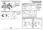
J Adjusting the Viewing Position of your Display
Step 1
Loosen the two M8x45mm screws, and adjust the
tilt angle of the display to the required position.
Tighten the two locking screws with the Long
6mm Allen Key provided.
-5° to 25°
Tilt
Collar Front
6mm Allen
Key
M8 Small
Washer
Swivel Insert
M8x30mm
Screws
TM
M8x45mm
Screw Tighten
WARNING: Do not attempt to adjust tilt
angle without firstly loosening locking
screws.
Doing so may damage the product.
TH-3070- CTW
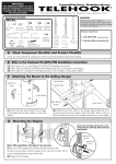
Component Checklist
IMPORTANT:
Ensure you have received all parts against the component checklist prior to installing.
Clinch Nuts
Collar Rear
Step 1
Step 2
Attach the three Swivel Inserts to the hanger in the height that
you have chosen for the mounting of the display.
Attach the front and rear Hanger Pole Collar so that it sits on
the swivel collars as shown above. Tighten the M8x30mm
screws so that the hanger pole collars is secure, however do
not over tighten.
Flat Panel Ceiling Mount
Wall Mount Bracket (Left)
Loosen
Long 6mm
Allen Key
Ceiling Mount
NOTE:
Wall Mount Bracket (Right)
Slider (x2)
Collar Joiner
Wall Mount Horizontal Bar
H Attaching the Mount to the Ceiling Hanger
3. Horizontal Adjust
2. Pan Adjust
Ceiling
Mount
Ceiling Mount
Cover
Cables
Ceiling
Mount
Ceiling Mount
Cover
Ceiling Mount Cover
2
Extension Hanger
Inner Hanger
Hanger Joiner
Bits Box
Tighten
Cables
3
6mm Allen Key
Cut Out
1
-5° to 5°
Horizontal Bar
Collar Front Collar Rear Swivel Insert
(x3)
Adhesive Vinyl M6 x12mm M8 x45mm M8 Small
Grub Screw Locking Screws Washer
Strip (x6)
(x2)
(x2)
(x3)
M10 Coach M10 Steel Nylon Plug
Screw (x4) Washer (x4)
(x4)
M8 x55mm M8x30mm
Screw
Screw (x4)
360° Rotation
Step 1
Step 2
To use the in-built cable management, remove the Ceiling
Mount Cover and feed the cables through the cable hole.
Cut out enough space in the Ceiling Mount Cover to allow
the cables to exit from, then push the Ceiling Mount Cover
up, until in sits flush with ceiling.
To adjust the pan position of the display, rotate the Hanger Pole
Collar to the desired position. Once in position, tighten all 4
M8x30mm screws as tight as possible to lock the display in
position.
K Attaching the Adhesive Vinyl
Adjust grub screw 1 until the display sits level. Once the
display is level, tighten grub screw 2 until it firmly tightens onto
the horizontal bar. Tighten grub screw 3 firmly until it firmly
tightens onto the horizontal bar and prevents it from moving.
L Security Option
I Mounting the Display
For added security you may
choose to attach a padlock to
one or both brackets to prevent
the theft of the display. It is
recommended that the padlock
should have a shackle diameter
of 5mm (3/16”).
Hanger
Note: The brackets
should rest on the
horizontal bar with the
slider between the
bracket.
M8 Small
Washer
Tighten
M8x45mm
Screw
Adhesive
Vinyl
The installer should
satisfy himself that the
ceiling is strong
enough to support the
Telehook Flat Panel
Ceiling Mount unit of
14kgs (31lbs) plus the
maximum allowable
monitor weight of
91kgs (200lbs).
Total of 105kgs
(231lbs).
TOOLS REQUIRED:
z Power Drill
z 12mm (1/2”) Drill Bit
z 7mm (9/32”) Drill Bit
z Adjustable wrench
Multi
M8 x10mm
Screw (x24) Washer (x6)
A Mounting the Ceiling Mount
NOTE: Ensure all four M10 Coach Screws are used when mounting the Ceiling Mount.
12mm (1/2”)
Hole
Padlock
(not supplied)
The manufacturer
does not accept
responsibility for
incorrect installation.
M8 x16mm M6 x16mm M5 x16mm M4 x16mm
5mm
3mm
Mounting Mounting Mounting
Allen Key Allen Key Mounting
Screws (x6) Screws (x6) Screws (x6) Screws (x6)
Timber Beam Mounting Option
Masonry Mounting Option
The Telehook Flat Panel Ceiling Mount’s
set up is now complete. The remaining
unused holes can be covered using the
6 white adhesive vinyl strips for improved
aesthetics. Peel the backing from the
strip and apply the adhesive side onto
the hanger(s) so that they cover the
unused holes.
Note: The Vinyl Strips may need to be cut to length
depending on the hanger configuration chosen.
Note: This operation will require two persons.
Lift the display with brackets attached and hook the brackets over the
sliders. Hold the display firmly and insert the two M8x45mm screws
and tighten by using the Long 6mm Allen Key.
Long 6mm
Allen Key
Telehook Flat Panel
Ceiling Mount
supports a maximum
weight of 91kgs
(200lbs)
Nylon Plug
5mm (3/16”)
diameter shackle
OR
M10 Washer
Masonry
Ceiling
Timber
Beam
7mm (9/32”)
Hole
M10 Washer
Long 6mm
Allen Key
No portion of this document or any artwork contained herein should be reproduced in any way without the express written consent of Atdec Pty Ltd.
Due to continuing product development, the manufacturer reserves the right to alter specifications without notice. Published: 11.09.08 C
M10 Coach
Screw
M10 Coach
Screw
B Attaching the Ceiling Mount Cover
Option 3: 1070mm (421/8”) - 1820mm (715/8”)
Option 4: 1650mm (65”) - 2000mm (783/8”)
D Attaching the Brackets to the Display
Step 1
Attach left and right brackets to the rear of your display. Select M4, M5, M6 or M8 fasteners to suit your display. Ensure
a minimum of 2 fasteners are used per bracket. Clinch nuts must be positioned as shown (internally).
Ceiling
Mount Cover
Ceiling Mount
Cover
=
=
M8 Screw Hole
Ceiling Mount
M6 Screw Hole
Ceiling Mount
Cover
Ceiling Mount
Ceiling Mount
TOP
M8x10mm
Screws
False Ceiling
M5 & M4
Screw Hole
Inner Hanger
Inner Hanger
M8x10mm
Screws
Multi Washer
Clinch Nuts
Ceiling Mount
Cover
Extension
Hanger
If the ceiling mount is attached where a false ceiling is used,
the ceiling mount cover should be used to hide the hole in
the false ceiling.
Slide cover plate up.
E
Hanger Joiner
Collar Joiner
Option 1: 220mm (811/16”) - 470mm (181/2”)
Option 2: 650mm (251/2”) - 1000mm (393/8”)
Ceiling Mount
Ceiling Mount
Cover
Option 3:
To mount the display from1070mm (42 /8”) to 1820mm (71 /8”)
please use the above set up as shown. The Inner Hanger
position can be adjusted and the Collar can be mounted along
the holes on the Extension hanger. Settings are at 50mm (2”)
increments.
*See Note.
Ceiling Mount
Cover
5
To mount the display from 1650mm (65”) to 2000mm (78 /8”)
please use the above set up as shown. Note that the Inner
Hanger position can be adjusted, and that the Collar will be
mounted to the Collar Joiner. Settings are at 50mm (2”)
increments.
If you intend to mount the display along the hanger
as per Option 1 or Option 3, you may choose to cut
the excess hanger, for improved aesthetics and cable
management.
Ceiling Mount
Inner
Horizontal Bar
Collar Front
Slider
Horizontal
Rail
3
*NOTE:
M8x10mm
Screws
3mm Allen Key
5mm
Allen Key
Option 4:
1
Attaching Horizontal Rail
M6x12mm
Grub Screw
C Mounting Options
There are four possible mounting options for the Telehook Flat Panel Ceiling Mount. The selected mounting option will be determined by the required distance from the ceiling to the centre of the display.
Use the supplied Multi Washer as shown
above. Ensure that the tightest fitting hole
in the washer is used for the specific size
screw. Note distance X, for use in
the following steps.
X
Extension
Hanger
Step 2:
Slot
M8x55mm
Screw
Grub Screw
Step 1
Step 2
Insert the Horizontal Bar into the Hanger Pole Collar. Ensure
the slots on the Horizontal Bar are facing towards the Collar.
Insert the M8x55mm Screw to hold the bar in position.
Loosely insert the three M6x12mm grub screws.
Attach the two sliders to the Horizontal Bar, one on either
side. Tighten the grub screw into the slot, however do not
tighten firmly as the position will need to be adjusted to suit
your display.
F
Position Sliders
Step 1
Accurately position sliders at Distance X as recorded in Section D. Ensure the
Sliders are equally spaced along the centre Horizontal Bar.
Hanger
=
=
Tighten
Collar Joiner
Slider
Cut
Option 1:
Option 2:
(181/2”)
To mount the display from 220mm (8 /16”) to 470mm
please use the above set up as shown. Settings are at 50mm
(2”) increments.
*See note.
11
To mount the display from 650mm (251/2”) to 1000mm
(393/8”) please use the above set up as shown. The Inner
Hanger position can be adjusted at 50mm (2”) increments.
Grub
Screw
Step 2
Point of Contact
Distance X
Secure slider in position and tighten firmly with
supplied allen key. Ensure that the grub screw
tightens into the slot on the horizontal bar.