1
Register your product and get support at
www.philips.com/welcome
SLV4200
EN
Wireless TV Link
Table of contents
1
1.1
1.2
1.3
1.4
1.5
Important
Power requirements
Conformity
Recycling and disposal
Electric, Magnetic and
Electromagnetic Fields ("EMF")
Installation requirements
4
4
4
5
5
6
2
2.1
2.2
Your Wireless TV link
What’s in the box
Overview of the
Wireless TV link
7
7
3
3.1
3.2
Getting started
Connect transmitter
Install the remote control
blaster cord
Connect receiver
Enjoy
Select Source
Remove interference on TV2
Improve the quality of the
reception with the antenna
9
9
3.3
3.4
3.5
3.6
3.7
7
10
10
11
12
12
12
4
Technical Data
5
Frequently asked questions 14
6
6.1
6.2
Information
Warranty
Glossary
16
16
16
7
INDEX
17
8
Declaration of Conformity 18
Table of contents
13
3
1
Important
Take time to read this user manual before
you use your wireless TV link.
It contains important information and
notes regarding your wireless TV link.
1.1
Power requirements
• Connect the power adapters only to a
100-240V AC 50/60Hz power supply.
• The Electrical network is classified as
hazardous. The only way to power
down the charger is to unplug the
power supply from the electrical
outlet. Ensure that the electrical outlet
is always easily accessible.
! Warning
To avoid damage or malfunction:
• Do not expose the wireless TV link to
excessive heat caused by heating
equipment or direct sunlight.
• Do not drop your wireless TV link or
allow objects to fall on your wireless
TV link.
• Do not use any cleaning agents
containing alcohol, ammonia, benzene,
or abrasives as these may harm the
set.
• Do not use the product in places
where there are explosive hazards.
• Do not let small metal objects come
into contact with the product. This can
deteriorate audio quality and damage
the product.
• Active mobile phones in the vicinity
may cause interference.
• Do not open your product as you
could be exposed to high voltages.
• Do not allow the charger to come into
contact with liquids.
4
• Do not allow the TV link to come into
contact with liquids.
• Use only with provided power supply.
Manufacturer: Concord.
Model Name: CM-3AD09005.
• Power supply information for receiver
and transmitter
Input: AC100-240V/120mA,
50Hz/60Hz
Output: DC9V/500mA
About operating and storage
temperatures:
• Operate in a place where temperature
is always between 0 and 40ºC (32 to
103ºF).
• Store in a place where temperature is
always between -10 and 70ºC (14 to
157ºF).
1.2
Conformity
This product has been designed, tested
and manufactured according the
European R&TTE directive 1999/5/EC
Following this directive, this product can
be brought into service in the following
states:
Class identifier. This is a class 1 product.
We, Philips, declare that the product is in
compliance with the essential
requirements and other relevant
provisions of Directive 1999/5/EC. You
can find the Declaration of Conformity
on www.p4c.philips.com.
Important
1.3
A financial contribution has been
paid to the associated national
recovery & recycling system.
The labeled packaging material is
recyclable.
Recycling and disposal
Disposal instructions for old products.
The WEEE directive (Waste Electrical
and Electronic Equipment; 2002/96/EC)
has been put in place to ensure that
products are recycled using best
?available treatment, recovery and
recycling techniques to ensure human
health and high environmental protection.
1.4
1.
Your product is designed and
manufactured with high quality materials
and components, which can be recycled
and reused.
Do not dispose of your old product in
your general household waste bin.
2.
Inform yourself about the
local separate collection
system for electrical and
electronic products marked
by this symbol:
Use one of the following disposal options:
1. Dispose of the complete product
(including its cables, plugs and
accessories) in the designated WEEE
collection facilities.
2. 2. If you purchase a replacement
product, hand your complete old
product back to the retailer. He
should accept it as required by the
WEEE directive.
Packaging information:
Philips has marked the packaging with
standard symbols designed to promote
the recycling and appropriate disposal of
your eventual waste.
Important
3.
4.
5.
Electric, Magnetic and
Electromagnetic Fields
("EMF")
Philips Royal Electronics
Manufactures and sells many
consumer oriented products which
usually, as with any electronic
apparatus, have the ability to emit
and receive electro magnetic signals.
One of Philips' leading Business
Principles is to take all necessary
health and safety precautions for our
products, to comply ?with all
applicable legal requirements and to
stay well within the EMF standards
applicable at the time of producing
the ?products.
Philips is committed to develop,
produce and market products that
cause no adverse health effects.
Philips confirms that if its products
are handled properly for their
intended use, they are safe to use
according to scientific ?evidence
available today.
Philips plays an active role in the
development of international EMF
and safety standards, enabling Philips
to anticipate further ?developments
in standardisation for early
Integration in its products.
5
1.5
Installation requirements
The product transmits and receives radio
waves when it is switched on. The
product complies with the standards that
are defined for it.
As the product is based on RF
technology, the quality of the image can
be influenced by microwave ovens,
Bluetooth, Wifi etc. Therefore the
product can suffer from the same kinds of
interference as GSMs, portable radios
and other RF-based products.
6
Important
2
Your Wireless TV link
Congratulations on your purchase and welcome to Philips!
To fully benefit from the support that Philips offers, register your product at
www.philips.com/welcome.
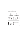
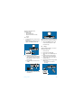
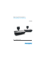
2.1
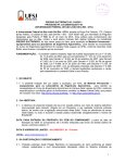
What’s in the box
A. Transmitter
C. SCART
cable
2.2
D. RCA/SCART
cable
B. Receiver
E. Power
F. Remote control G. User manual
adapter (2x)
blaster cord
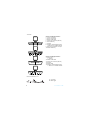
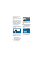
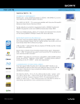
Overview of the Wireless TV link
Transmitter
Control and display elements
1 SOURCE switch
Your Wireless TV link
7
Transmitter
Control and display elements
2 green: on (source 1)
3 green: on (source 2)
4 Power on/off switch
5 Power input connector (DC 9V)
6 RCA cable entry
7 Antenna
8 Wireless channel selection switch
> Select from 4 available channels
9 Remote control blaster cord port
10 SCART cable entry
Control and display elements
11 Power light:
> green: on
12 Power on/off switch
13 Power input connector (DC 9V)
14 Antenna
15 SCART cable
16 Wireless channel selection switch
> Select from 4 available channels
Remote control blaster cord
17 Connector
18 Blaster light
8
Your Wireless TV link
3
Getting started
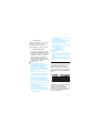
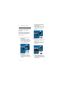
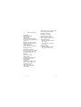
3.1
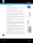
Connect transmitter
c. Plug the RCA connectors into
the corresponding ports of the
transmitter (A).
d. Plug the SCART connector of
the RCA/SCART cable into the
SCART port of the video
source 2.
Two video sources can be connected at
the same time to the SLV4200
transmitter.
The video sources can be following:
DVD players/recorders, VCR, Game
Consoles, Cable & Satellite Set-TopBoxes, and more.
1
2
Connect video source 1 to the
transmitter (A).
a. Unplug the Scart cable that
connects source 1 to the TV1.
b. Connect the transmitter to the
source 1 using the supplied
SCART/SCART cable (C ).
Connect video source 2 to the
transmitter (A).
a. Unplug the Scart cable that
connects source 2 to the TV1.
b. Take the supplied RCA/SCART
cable (D).
Getting started
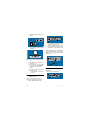
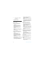
3.
Connect TV1
a. Plug the SCART cable from TV1
into the SCART connector of
source 1.
b. Plug the SCART cable from TV1
into the SCART connector of
source 2.
4.
Connect the power adapter
a. Take the supplied power adapter
(E) to plug the connector into the
DC 9V power connector on the
transmitter (A).
9
b. Plug the adapter into the power
outlet.
2.
3.
c. The green LED on the front panel
should be on.
Connect the remote control blaster
cord (F) to the IR socket.
Position the blaster light in front of
the video source. Just put it in front
of the IR sensor on the front panel.
Note: See the FAQ “How can I find the IR
sensor on the video source?” for locating
the IR sensor on the front panel of the
video source.
Note: if it is not the case, press the ON/
OFF switch on the back of the product.
5.
3.2
Check that TV1 is working well
a. Switch on TV1
b. Check that TV1 is working well.
c. Switch on the connected video
source for the video source
chosen.
d. Check if TV1 shows the image of
the video source.
> The transmitter is connected
correctly.
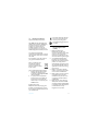
3.3
Connect receiver
Preparation
- Switch on the transmitter (A).
Install the remote control
blaster cord
The remote control blaster cord
transmits IR signal to Source devices.
1. Switch off the transmitter (A).
10
Getting started
- Switch on the Video source.
- Take these items:
• Receiver (B)
• Power adapter (E)
• Remote control of the video
source.
- Go to TV2.
1.
Connect the receiver to the second
TV (TV2)
Plug the SCART cable of the receiver
(B) into the SCART port of TV2.
Note: if it is not the case, press the ON/
OFF switch on the back of the product.
3.
3.4
Set the CHANNEL switch to the
same channel number as on the
transmitter (A).
Enjoy
All the operations listed on 3.1 and 3.3
should have been done.
1.
2.
3.
2.
Connect the power adapter
a. Take the supplied power adapter
(E) to plug the connector into the
DC 9V power connector on the
Receiver (B).
b. Plug the adapter into the power
outlet.
4.
5.
6.
Switch on TV2.
Switch on the receiver (B).
Select the correct SCART input on
TV2.
Point the remote control of the
video source to the receiver (B).
Operate the video source with its
remote control.
Check if TV2 shows the image of the
video source.
> The receiver is connected
correctly.
c. The green LED on the front panel
should be on.
Getting started
11
Note: If the VCR or DVD recorder
records a television program, you watch
the recorded channel.
Note: how to watch a video source on
TV1?
Use your TV1 and your video source as
usual to watch a video source on TV1.
Note: In case the video source does not
react the IR control blaster might not be
installed properly. See the FAQ “How
can I find the IR sensor on the video
source?” for locating the IR sensor on the
front panel of the video source.
3.
4.
3.7
3.5
Select Source
Switch between the two video source
images by pushing the source switch on
the Transmitter.
3.6
Remove interference on TV2
Depending on your specific situation,
after completing 3.1 and 3.3, you may
experience some interference.
1.
2.
12
Find the CHANNEL switch on the
receiver (B).
Set the CHANNEL switch to the
same number as on the transmitter
(A).
Improve the quality of the
reception with the antenna
1.
Adjust the orientation of the
antenna of the receiver for best
picture.
2.
Best transmission performance you
obtain when the front sides of the
transmitter and receiver antennas
are "faced" to each other in an
imaginable straight line.
Find the CHANNEL switch on the
transmitter (A). There are 4
channels. You may have to change
the channels in case of interferences.
Set the CHANNEL switch to a
different number on the transmitter
(A) in case of interferences.
Getting started
4
Technical Data
Transmitter
System: RF (TV-LINK)
Modulation: FM
Weight: 0.27kg
Dimensions: 120X182X40.2mm
Carrier Frequency: 5750~5855MHz
Channels: 4
Radiated Output Power: 25mW
Effective Transmission Range: 35m
Audio Input level: 2V
Video Input level: 1.1V
Power requirements: 9V/500mA
IR Extender Receiver
RF Frequency: 433.92MHz
Receiving Sensitivity: -90 ~ -98 dBm
IR carrier Frequency: 30~57kHz
> 3m
IR LED Operation Range: =
Audio frequency response: 40Hz~15kHz
Power Requirements: 9V/500mA
IR Extender Transmitter
IR Frequency: 433.92MHz
RF Output Power: 7~9dBm
IR carrier Frequency: 30~57kHz
> 7m
IR Sensor Operation Range: =
Temperature range
• Operation: Between 0 and 40ºC
(32 to 103ºF ).
• Storage: Between -10 and 70ºC
(14 to 157ºF).
Relative humidity
• Operation: Up to 90% at 40ºC
• Storage: Up to 90% at 40ºC
Receiver
System: RF (TV-LINK)
Weight: 0.33kg
Dimensions: 120X182X40.2mm
Playback frequency range:
5750~5855MHz
Channels: 4
Audio S/N ratio: 50dB (at 15m)
Video S/N ratio: 43dB (at 15m)
Audio Output level: 2V
Video Output level: 1.1V
Video Frequency Response:
50Hz~5.5MHz
Technical Data
13
5
Frequently asked
questions
www.philips.com/support
In this chapter, you will find the most
frequently asked questions and answers
about your product.
No image or wrong image on TV1
• Make sure the video source is
switched on.
• Make sure the video source is
connected to the transmitter (A).
• Make sure the transmitter (A) is
connected to TVI.
• Make sure the transmitter (A) is
switch on.
• Make sure SCART cables are firmly
inserted.
• Make sure the correct SCART input
on TV1 is selected.
No image or wrong image on TV2
• Make sure SCART cables are firmly
inserted.
• Make sure the receiver (B) is
connected to TV2.
• Make sure both receiver (B) and
transmitter (A) are switched on.
• Make sure the video source is
switched on.
• Make sure the correct SCART input
on TV2 is selected.
• If the video source gives proper image
on TV1, make sure the video source
gives video signal in CVBS mode.
14
• Change the wireless channel that is
used for communication.
See “Remove interference on TV2” on
page 12.
• The receiver (B) is out of range of the
transmitter (A). The number of walls
and ceilings between the receiver (B)
and transmitter (A) restricts the
distance.
Interference in the image on TV2
• Slightly change the position of the
receiver (B) or the transmitter (A).
• Change the wireless channel that is
used for communication.
See “Remove interference on TV2” on
page 12.
• The receiver (B) is out of range of the
transmitter (A). The number of walls
and ceilings between the receiver (B)
and transmitter (A) restricts the
distance.
The video sources do not respond to the
remote control commands from TV2
• Point the remote control directly to
the receiver (B).
• Replace the batteries of the remote
controls with new ones.
• Install the remote control blaster cord
(F).
See “Install the remote control blaster
cord” on page 10.
Note: The maximum operating distance
of the remote control is 7m.
Buzzing sound when you use the remote
control.
• Slightly change the position of the
receiver or the transmitter until the
buzzing sound stops.
Frequently asked questions
Easylink feature does not work.
• Check if the TV and VCR support
Easylink.
• Check if you used full-wired SCART
cables.
Black and white image with S-VHS VCR.
• (Super Video Home System Video/
Cassette/Recorder)
• Check if the SCART connector of the
S-VHS VCR gives signal in CVBS.
(Composite Video Broadcast Signal).
See its user manual.
How can I find the IR sensor on the video
source?
• The blaster light needs to be
positioned precisely on the IR sensor
of the video source. Some equipments
have the letters IR at the front
indicating the location of the IR sensor.
In case there is no indication the
position can be found by moving the
blaster light slowly over the front of
the video source while a 2nd person
operates the remote control at the
location of TV2. At least make sure
that the remote control is out of range
of the video source. When the video
source starts to react the IR sensor
location is found. Mount the blaster
light on this location at the front of the
video source.
• Another possibility is to move the
remote control over the front of the
video source while operating it. Once
the video source starts to react the
location of the IR sensor is found. This
method is less accurate and does not
work for each remote control model.
• Also consult the documentation of
your video source to locate the IR
sensor.
Frequently asked questions
How can I watch a different channel on
TV1 and TV2 simultaneously?
• Watching two different channels is
only possible if you use two tuners.
For example TV1 uses its internal
tuner and TV2 uses the tuner of the
VCR. For switching channels on TV2
you switch then between the channels
stored in the VCR. Note that this is
not possible when you have a digital
cable.
• Connect your antenna cable to both
your TV1 and your VCR.
• Search for the TV channels on your
VCR and store them in your VCR.
• Connect the transmitter (A) to the
output of the VCR.
• Connect the receiver (B) to the input
of TV2.
• To switch TV channels on TV2 switch
the channel on your VCR.
15
6
Information
6.1
Warranty
One year limited warranty
For 12 month from the date of purchase
the manufacturer repairs or replaces any
faulty product free of charge, subject to
proof of purchase, provided the fault has
not been caused by improper handling or
use, and provided the product has not
been damaged, whether as a result of an
accident or of repair by others than the
manufacturer.
6.2
Glossary
CVBS:
Video standard for showing colors on a
TV.
Easylink:
Gives a VCR or DVD recorder the
possibility to automatically take over the
preset programming of the TV.
RCA:
Separate connectors to connect audio
video equipment.
RF technology:
Technology based on radio frequency,
used for wireless connections.
SCART:
Single connector to easily connect audio
and video equipment.
16
Glossary
7
INDEX
C
Channel 12
Connect receiver 10
Connect transmitter 9
E
Enjoy 11
F
Frequently asked questions 14
G
Getting started 9
I
Information 16
Interference 12
O
Overview of the Wireless TV link 7
R
Remote control blaster cord 10
T
Technical Data 13
W
What’s in the box 7
Y
Your Wireless TV link 7
INDEX
17
8
Declaration of Conformity
© 2009 Koninklijke Philips Electronics N.V.
All rights reserved.
Reproduction in whole or in part is prohibited without
the written consent of the copyright owner.
Document number: SLV4200_12_EN_UM_V1.1
145- 142000002 (master EN)
Printed in China