1
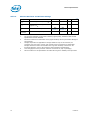
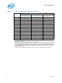
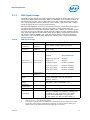
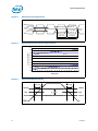
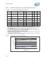
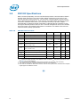
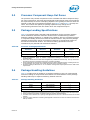
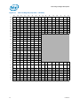
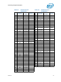
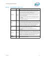
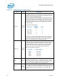
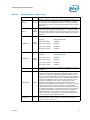
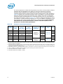
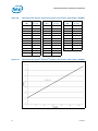
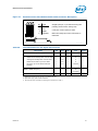
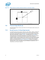
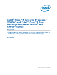
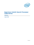
Electrical Specifications
2.8.5
BCLK[1:0] Specifications (CK410 based Platforms)
Table 18.
Front Side Bus Differential BCLK Specifications
Symbol
Parameter
Min
Typ
Max
Unit
Figure
Notes1
VL
Input Low Voltage
-0.150
0.00
0
N/A
V
3
-
VH
Input High Voltage
0.660
0.70
0
0.850
V
3
-
VCROSS(abs)
Absolute Crossing
Point
0.250
N/A
0.550
V
3, 4
2, 3
VCROSS(rel)
Relative Crossing
Point
0.250 +
0.5(VHavg – 0.700)
N/A
0.550 +
0.5(VHavg – 0.700)
V
3, 4
4, 3, 5
ΔVCROSS
Range of Crossing
Points
N/A
N/A
0.140
V
3, 4
-
VOS
Overshoot
N/A
N/A
VH + 0.3
V
3
6
VUS
Undershoot
-0.300
N/A
N/A
V
3
7
VRBM
Ringback Margin
0.200
N/A
N/A
V
3
8
VTM
Threshold Region
VCROSS – 0.100
N/A
VCROSS + 0.100
V
3
9
NOTES:
1. Unless otherwise noted, all specifications in this table apply to all processor frequencies.
2. Crossing voltage is defined as the instantaneous voltage value when the rising edge of BCLK0 equals the
falling edge of BCLK1.
The crossing point must meet the absolute and relative crossing point specifications simultaneously.
VHavg is the statistical average of the VH measured by the oscilloscope.
VHavg can be measured directly using “Vtop” on Agilent* oscilloscopes and “High” on Tektronix* oscilloscopes.
vershoot is defined as the absolute value of the maximum voltage.
Undershoot is defined as the absolute value of the minimum voltage.
Ringback Margin is defined as the absolute voltage difference between the maximum Rising Edge Ringback
and the maximum Falling Edge Ringback.
9. Threshold Region is defined as a region entered around the crossing point voltage in which the differential
receiver switches. It includes input threshold hysteresis.
3.
4.
5.
6.
7.
8.
Figure 6.
Differential Clock Crosspoint Specification
650
Crossing Point (mV)
600
550
550 mV
500
450
550 + 0.5 (VHavg - 700)
400
250 + 0.5 (VHavg - 700)
350
300
250
250 mV
200
660 670 680 690 700 710 720 730 740 750 760 770 780 790 800 810 820 830 840 850
VHavg (mV)
Datasheet
31