1
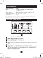
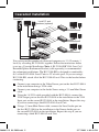
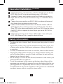
y
nt n: r a ite ty
ra io y fo p L ran
ar trat toda E Trip /war
W is ne E om
g nli FR e.c
Reter o in a ipplit
w .tr
gis o
re ce t ww
w
an —
ch uct
od
pr
Owner’s Manual
VGA with Audio Over
Cat5 Extender/Splitter
Local Unit
Model: B132-004A
Español
7
8
Français
15
Tripp Lite World Headquarters
1111 W. 35th Street, Chicago, IL 60609 USA
(773) 869-1234 • www.tripplite.com
Note: Follow these instructions to ensure proper operation and prevent damage
to this device and its connected equipment.
200901115 93-2869.indd 1
Copyright © 2009 Tripp Lite. All rights reserved.
All trademarks are the property of their respective owners.
1
2/17/2009 4:03:42 PM
Package Contents
• B132-004A VGA with Audio Over Cat5 Extender/Splitter Local Unit
• 1 ft. VGA Cable
• 5V, 2A Power Supply
• Owner’s Manual
Product Features
• Transmits and extends a VGA and Audio signal to up to 4 monitors; up to
500 ft using standard Cat5e/6 cable, or up to 1,000 ft (1024 x 768, 3db)
using Zero-Skew UTP cable
• Expand the number of connected monitors by chaining up to 3 B132-004A
Extender/Splitters together
• Features a HD15 and Audio port for local monitor and speaker connection
• Compatible with VGA, SVGA, XGA, SXGA and UXGA computer resolutions
• Supports video resolution up to 1920 x 1440
• Compatible with all operating systems
Optional Accessories
• B132-100A VGA with Audio over Cat5 Extender/Splitter Remote Unit
• B132-004-RB VGA over Cat5 Extender/Splitter Rackmount Bracket
• P504-Series Monitor Cables with 3.5 mm Audio; HD15 Male/Male and 3.5
mm Male/Male
• P502-Series Monitor Cables with RGB Coax, HD15 Male/Male
• P312-Series 3.5 mm Mini-Stereo Cable
• P524-Series Zero-Skew UTP Bulk Cable
• P525-Series Zero-Skew UTP Patch Cable
• N001- or N002-Series Cat5e Patch Cables
• N201-Series Cat6 Patch Cables
Specifications
Signal Type���������������������VGA, SVGA, XGA, UXGA and WUXGA
(up to 1920 x 1440)
Video Amplifier
Bandwidth�����������������������350 Mbps
Input DDC Signal�����������0.7 Volts p-p (TTL)
2
200901115 93-2869.indd 2
2/17/2009 4:03:42 PM
Specifications (continued)
Signal Noise Ratio����������90dB
Ports��������������������������������(x2) HD15 Female, (x2) 3.5 mm Female,
(x4) RJ45 Female
Power Supply������������������Input: 100-240V, 50/60 Hz; Output: 5V, 2A
Dimensions (Inches)�������1.1 (H) x 5 (W) x 4 (D)
Weight (lbs)���������������������0.9
Note: Specifications are subject to change without notice. Mass and dimensions are
approximate; please take the products as a standard.
Function Description
5
6 3 4
1
2
7
Source Video-In Port: HD15 Female.
Local Video-Out Port: HD15 Female.
Source Audio-In Port: 3.5 mm Female.
Local Audio-Out Port: 3.5 mm Female.
Power LED: LED illuminates when the unit is plugged in and receiving
power.
6 Power Jack: 5V, 2A power supply connects to the unit here.
7 Output Ports: (x4) RJ45 Female; connect Cat5e/6 cable* between each
port and a B132-100A VGA with Audio Over Cat5 Extender/Splitter
Remote Unit (sold separately).
1
2
3
4
5
* Use Zero-Skew UTP cable when extending the signal over 500 ft from the source.
200901115 93-2869.indd 3
3
2/17/2009 4:03:42 PM
Installation
B132-100A
B132-004A
Note: Test to make sure the entire installation works properly before pulling cables
through ceilings/walls.
1 Connect your computer to the Video Source port on the B132-004A
using a VGA cable.
2 Connect your computer to the Audio Source port on the B132-004A
using a 3.5 mm Mini-Stereo cable.
3 (Optional) Connect a local monitor to the Local Video port on the
B132-004A using a VGA cable.
4 (Optional) Connect local speakers to the Local Audio port on the
B132-004A using a 3.5 mm Mini-Stereo cable.
5 Connect the power supply to the B132-004A and plug it into an
appropriate power source.
6 Connect the B132-004A Local Unit to a B132-100A Remote Unit (sold
separately) using Cat5e/6 cable*. One B132-100A is required for each
Output port on the B132-004A Local Unit.
7 Follow the instructions in the Owner’s Manual that comes with your
B132-100A Remote Unit to complete the installation.
* Use Zero-Skew UTP cable when extending the signal over 500 ft from the source.
200901115 93-2869.indd 4
4
2/17/2009 4:03:43 PM
Cascaded Installation
Source PC
Local PC and
Speakers (optional)
You can expand the number of connected computers to 13 (12 remote, 1
local) by cascading B132-004A’s together. Follow the instructions below
to set up a Cascaded Installation. Note: A B132-004-RB VGA Over Cat5
Extender/Splitter Rackmount Bracket (sold separately) is recommended
for rackmount installations. The B132-004-RB is designed to comfortably
fit 3 of the B132-004A Local Units in 1U of rack space. If you are using a
B132-004-RB, attach all of the B132-004A Local Units to the bracket before
continuing.
1 Connect your computer to the Video Source port on the first B132-004A
in the installation using a VGA cable.
2 Connect your computer to the Audio Source using a 3.5 mm Mini-Stereo
cable.
3 Using the 1 ft VGA cable provided with the B132-004A, connect the
VGA Output port on the first B132-004A in the installation to the VGA
Input port on the second B132-004A in the installation. Repeat this step
if you are connecting a third B132-004A Local Unit.
4 Using a 3.5 mm Mini-Stereo cable, connect the Local Audio port on
the first B132-004A in the installation to the Source Audio port on
the second B132-004A in the installation. Repeat this step if you are
connecting a third B132-004A Local Unit.
200901115 93-2869.indd 5
5
2/17/2009 4:03:43 PM
Cascaded Installation (continued)
5 (Optional) Connect a local monitor to the Local Video port on the last
B132-004A Local Unit in the installation using a VGA cable.
6 (Optional) Connect local speakers to the Local Audio port on the last
B132-004A Local Unit in the installation using a 3.5 mm Mini-Stereo
cable.
7 Connect the power supplies to all B132-004As in the installation and
plug them into an appropriate power source.
8 Connect the B132-004A Local Units to the desired number of B132100A Remote Units (sold separately) using Cat5e/6 cable. Use ZeroSkew UTP cable when extending the signal over 500 ft from the source.
One B132-100A is required for each Output port on the B132-004A
Local Units.
9 Follow the instructions in the Owner’s Manual that comes with your
B132-100A Remote Unit to complete the installation.
Safety Information
• To reduce the risk of electric shock, do not expose this product to rain or
moisture.
• Operate this product using only the included external power supply. Use
of other power supplies could impair performance, damage the product,
or cause fire.
• Use only recommended accessories to avoid fire, shock or other hazards.
• Unplug this product before cleaning. Use a damp cloth for cleaning. Do
not use cleaning fluids or aerosols, which could enter the unit and cause
damage, fire or electrical shock.
• Do not attempt to service the unit. Instead, disconnect it and contact your
Authorized Reseller or technician.
• Use of this equipment in life support applications where failure of this
equipment can reasonably be expected to cause the failure of the life support equipment or to significantly affect its safety or effectiveness is not
recommended. Do not use this equipment in the presence of a flammable
anesthetic mixture with air, oxygen or nitrous oxide.
200901115 93-2869.indd 6
6
2/17/2009 4:03:44 PM
WARRANTY REGISTRATION
Visit www.tripplite.com/warranty today to register the warranty for your new Tripp Lite product. You’ll be
automatically entered into a drawing for a chance to win a FREE Tripp Lite product!*
* No purchase necessary. Void where prohibited. Some restrictions apply. See website for details.
1-YEAR LIMITED WARRANTY
Seller warrants this product, if used in accordance with all applicable instructions, to be free from original
defects in material and workmanship for a period of 1 year from the date of initial purchase. If the product
should prove defective in material or workmanship within that period, Seller will repair or replace the
product, in its sole discretion. Service under this Warranty can only be obtained by your delivering or
shipping the product (with all shipping or delivery charges prepaid) to: Tripp Lite; 1111 W. 35th Street;
Chicago IL 60609; USA. Seller will pay return shipping charges. Call Tripp Lite Customer Service at
(773) 869-1234 before sending any equipment back for repair.
THIS WARRANTY DOES NOT APPLY TO NORMAL WEAR OR TO DAMAGE RESULTING FROM
ACCIDENT, MISUSE, ABUSE OR NEGLECT. SELLER MAKES NO EXPRESS WARRANTIES
OTHER THAN THE WARRANTY EXPRESSLY SET FORTH HEREIN. EXCEPT TO THE EXTENT
PROHIBITED BY APPLICABLE LAW, ALL IMPLIED WARRANTIES, INCLUDING ALL
WARRANTIES OF MERCHANTABILITY OR FITNESS, ARE LIMITED IN DURATION TO THE
WARRANTY PERIOD SET FORTH ABOVE; AND THIS WARRANTY EXPRESSLY EXCLUDES
ALL INCIDENTAL AND CONSEQUENTIAL DAMAGES. (Some states do not allow limitations on how
long an implied warranty lasts, and some states do not allow the exclusion or limitation of incidental or
consequential damages, so the above limitations or exclusions may not apply to you. This Warranty gives
you specific legal rights, and you may have other rights which vary from jurisdiction to jurisdiction).
Tripp Lite; 1111 W. 35th Street; Chicago IL 60609; USA
Tripp Lite follows a policy of continuous improvement. Product specifications are subject to change
without notice.
Made in China.
200901115 93-2869.indd 7
Tripp Lite World Headquarters
1111 W. 35th Street, Chicago, IL 60609 USA
(773) 869-1234 • www.tripplite.com
7
200901115 93-2869
2/17/2009 4:03:44 PM