1
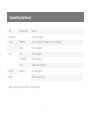
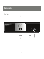
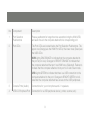
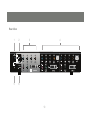
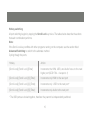
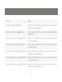
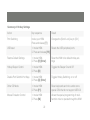
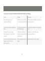
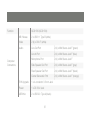
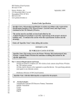
Installation Guide
USB 2.0 DVI KVMP Switch
GCS1782 / GCS1784
1
PART NO. M1024
Table of Contents
Package Contents
5
Advanced Configuration
20
Requirements
6
- Hotkey setting mode
21
Operating systems
7
- Summary of Hotkey Settings
22
Components
8
24
Hardware Setup
12
- Comparison of Default and
Alte Manual Port selection settings
Basic Operation
14
- Firmware up-grade mode
25
- Keyboard Operating platform
26
- Manual port selection
14
- Hotkey Switching
15
- Port ID numbering
- Direct port selection
- Auto Scanning
16
16
18
3
The Firmware Upgrade Utility
30
Troubleshooting
34
Specifications
35
Limited Warranty
40
Conventions
This manual uses the following conventions:
Monospaced Indicates text that you should key in.
[ ] Indicates keys you should press. For example, [Enter] means to press the Enter key. If keys
need to be chorded, they appear together in the same bracket with a plus sign between them:
[Ctrl+Alt].
1. Numbered lists represent procedures with sequential steps.
♦Bullet lists provide information, but do not involve sequential steps.
−>Indicates selecting the option (on a menu or dialog box, for example), that comes next. For
example, Start −> Run means to open the Start menu, and then select Run.
Indicates critical information.
4
Package Contents
1 USB 2.0 DVI KVMP Switch
[GCS1782] 2-Custom KVM Cable Sets (6ft)
[ GCS 1784] 4 custom Cable sets (6ft)
2 7.1 Audio cables (6ft) [GCS1782 only]
1 USB-to-PS/2 Converter
1 Firmware Upgrade Cable
1 Power Adapter
1 User Manual
1 Registration form
Verify All the components are present and that nothing was damaged in shipping. If you encounter a
problem, contact your dealer, or IOGEAR.
Read this manual thoroughly and follow the installation and operation procedures carefully to prevent
any damage to the unit, and/or any of the devices connected to it.
5
Requirements
Computers
A DVI-D port
USB Type A port
Audio ports (optional)
A USB mouse
A USB keyboard
Microphone and speakers (optional)
Monitor with a DVI input
Cables
Two (6 ft) DVI-D KVM custom cable sets
are provided with this package, which
incorporates cables for microphones (pink)
and 2.1 channel surround sound speakers
(green)
Two additional 6 ft audio cables are
included for 7.1 sound and are used in
conjunction with the 2.1 audio cables on
the KVM cable
6
Operating Systems
OS
Distribution
Windows
Linux
Unix
Novell
MAC
Version
2000 and higher
RedHat
9.0 and higher; Fedora Core 4 and higher
SuSe
9.0 and higher
AIX
4.3 and higher
FreeBSD
4.2 and higher
Sun
Solaris 9 and higher
Netware
6.0 and higher
OS 9.0 and higher
Note: Supports Linux Kernel 2.6 and higher.
7
Components
Front View
1
3
2
8
4
No
Component
Description
1
Port Selection
Pushbuttons
Press a pushbutton for longer than two seconds to bring the KVM, USB,
and audio focus to the computer attached to its corresponding port.
2
Port LEDs
The Port LEDs are located below the Port Selection Pushbuttons. The
upper one (Orange) are the KVM Port LEDs; the lower ones (Green) are
the USB LEDs:
KVM Lights DIM ORANGE to indicate that the computer attached to
the port is (On Line). Changes to BRIGHT ORANGE to indicate that
the computer attached that port has KVM focus (Selected). Flashes to
indicate that the computer attached to its port is in Auto Scan mode.
USB Lights GREEN to indicate that there is a USB connection to the
computer attached to the port. Changes to BRIGHT GREEN to indicate that the computer attached has access to the USB peripherals.
3
Console Ports (Audio)
Connections for your microphone and 2.1 speakers
4
USB 2.0 Peripheral Port
Connection for a USB peripheral device ( printer, scanner, etc.)
9
Rear View
1
2
5
6
3
4
10
No.
Component
Description
1
Firmware Upgrade Port
Connection for the firmware up grade cable
2
USB Console Ports
USB1.0 Keyboard and mouse connections*
3
Console Port Section
Connections for your monitor, mike, and speakers
4
CPU Port Section
Connections for the cables that link the switch to your computers. Each
CPU port is comprised of a microphone jack, speaker jack, USB type B
socket and a DVI connector
5
Power Jack
Power adapter connection
6
USB Peripheral Port
Connection for USB 2.0 peripherals ( printers, scanners, etc)
11
Hardware Setup
Make sure that power to all the devices you will be installing has been turned off. You must
unplug the power cords of any computers that have the Keyboard Power On function.
Cable Connection
To set up your GCS1782 installation, refer to the installation diagrams on the following pages (the
numbers in the diagrams correspond to the steps, below), and do the following:
1. Connect your USB keyboard and mouse into the USB Console Ports located on the unit’s back
panel.
2. Connect your microphone, speakers, and monitor into the Console ports located on the unit’s rear
panel
Note: The IOGEAR KVM cable set provided 2.1 channel surround sound only. You must use the
included audio cable for 7.1 audio
3. Using the KVM cable set, connect the DVI connector into any available DVI socket in the CPU Port
setion of the switch, then connect the accompanying USB, microphone and speaker connectors
into their corresponding USB, microphone, and speaker sockets.
12
4. At the other end of the cable, connect the
USB, video, microphone, and speaker cables
into their respective ports.
5. Connect your USB peripherals into the type
A sockets (one is located on the front, the
second is located on the rear).
5
1
2
3
6. Connect the power adapter that came with
your switch into the jack on the switch then
connect the adapter to an AC power source.
7. Verify your connections: ports are correct and
that the Icons match the connection type
6
8. Power on the computers.
2
5
4
13
Basic Operation
Manual Switching
There are two convenient methods to access the computers: Manual – pressing the port selection
pushbuttons located on the unit’s front panel; and Hotkey – entering key combinations from the
keyboard. Hotkey port selection is discussed in the next chapter.
Manual port selection:
Press and release a port selection pushbutton to focus the computer on the corresponding port. The
USB and Audio focus do not change (expect a 2 sec delay).
Press a port selection pushbutton twice to focus the audio on the corresponding port (expect a 2
sec delay).
Press and hold a port selection pushbutton for more than 2 seconds to focus KVM, USB, Audio and
the computer on the corresponding port.
Press and hold port selection pushbuttons 1 and 2 for more than 2 seconds to start Auto Scan
Mode, at 5seconds dwell time (default).
14
Hotkey switching
All port switching begins by tapping the Scroll Lock key twice. The tables below describe the actions
that each combination performs.
Note:
If the Scroll Lock key conflicts with other programs running on the computer, see the section titled
Advanced Switching to switch to the alternate method.
Cycling though the ports
Hotkey
Action
[Scroll Lock] [Scroll Lock] [Enter]
Increments the KVM, USB, and Audio focus to the next
higher port (GCS1784 - 4 wraps to 1)
[Scroll Lock] [Scroll Lock] [K] [Enter]
Increments only KVM to the next port
[Scroll Lock] [Scroll Lock] [U] [Enter]
Increments only USB to the next port*
[Scroll Lock] [Scroll Lock] [S] [Enter]
Increments only Audio to the next port
* The USB ports are locked together, therefore they cannot be independently switched.
15
Port ID Numbering
Each CPU port on the switch is assigned a port number (1 or 2 for the GCS1782 and 1,2,2,4 for the
GCS1784). The port numbers are marked on the rear panel of the switch and each switch LED has
a corresponding number for easy identification.
The Port ID of a computer is derived from the CPU port number it is connected to. For example, a
computer connected to CPU port 2 has a Port ID of 2.
The Port ID is used to specify which computer gets the KVM, USB peripheral, and / or audio focus
with the Hotkey port selection method.
Going Directly to a Port
Note: The n stands for the computer’s Port ID number. Replace the n with the appropriate Port ID
when entering hotkey combinations
16
Hotkey
Result
[Scroll Lock[ScrollLock][n][Enter]
Brings the KVM, USB hub, and audio focus to the computer
attached to the specified port.
[Scroll Lock] [Scroll Lock][n] [K] Enter]
Brings only the KVM focus to the computer attached to the
specified port.
[Scroll Lock] [Scroll Lock] [n] [U] [Enter]
Brings only the USB hub focus to the computer attached
to the specified port.
[Scroll Lock] [Scroll Lock] [n] [S] [Enter]
Brings only the audio focus to the computer attached to
the specified port.
[Scroll Lock] [Scroll Lock] [n] [K] [U] [Enter]
Brings the KVM and USB hub focus to the computer
attached to the specified port
[Scroll Lock] [Scroll Lock] [n] [K] [S] [Enter]
Brings the KVM and audio focus to the computer attached
to the specified port.
[Scroll Lock] [Scroll Lock] [n] [U] [S] [Enter]
Brings the USB hub and audio focus to the computer
attached to the specified port.
17
Auto Scanning
The GCS1782’s Auto Scan feature automatically cycles the KVM focus through the computer ports
at regular intervals. This allows you to monitor computer activity without having to switch from port
to port manually.
Note:
1. The n stands for the number of seconds that the CS1782 should dwell on a port before
moving on to the next. Replace the n with a number between 1 and 99 when entering this hotkey
combination.
2. While Auto Scan Mode is in effect, ordinary keyboard and mouse functions are suspended – only .
Auto Scan Mode compliant keystrokes and mouse clicks can be input. You must exit Auto Scan
Mode in order to regain normal control of the console (hit the space bar or the Esc key).
3. Although the video focus switches from port to port, the keyboard, mouse, and USB focus do not
switch. They remain on the port when Auto Scanning began.
18
Hotkey
Result
[Scroll Lock] [Scroll Lock] [A] Enter]
Invokes Auto Scan. The KVM focus cycles from port to port at
5 second intervals (default interval)
[Scroll Lock] [Scroll Lock] [A] [n] Enter]
The KVM focus cycles from port to port at n second intervals.
19
Advanced Configuration
Advanced Configuration
Hotkey Setting Mode
In some instances the default hotkey settings conflict with programs running on your computer, and in
some instances the default hotkeys either do not exist on your keyboard (MAC keyboards for instance
do not have a Scroll Lock key), or are inconvenient to use, so The Hotkey Setting Mode allows you to
select alternate configurations for the KVM’s hotkeys.
When HSM is active, the Caps Lock, and Scroll Lock LEDs flash in succession to indicate that HSM is
in effect. They stop flashing and revert to normal status when you exit HSM.
Ordinary keyboard and mouse functions are suspended – only Hotkey compliant keystrokes and
mouse clicks (described in the sections that follow), can be input.
At the conclusion of some hotkey operations, you automatically exit hotkey mode. With some
operations, you must exit manually. To exit HSM manually, press the Esc key, or the Spacebar.
20
Invoking Hotkey Setting Mode (Default)
1. Press and hold down [Num Lock] (the Clear key on MACs).
2. Press and release [-].
3. Release [Num Lock] (the Clear key on MACs).
To Toggle to or from the alternate Hotkey Setting Mode (HSM):
1. Press and hold down [Num Lock].
2. Press and release [-].
3. Release [Num Lock].
4. Press and release [H].
Invoking Hotkey Setting Mode (Alternate)
1. Press and hold down [Ctrl].
2. Press and release [F12].
3. Release [Ctrl].
NOTE: The term “invoke HSM” in the following table refers to the method chosen above
21
Summary of Hotkey Settings
Action
Key sequence
Result
Port Switching
Invoke your HSM
Press and release [ T ]
Changes the [Scroll Lock] key to [Ctrl]
USB reset
1. Invoke HSM.
2. Press and release [F5]
Resets the USB peripheral ports
Restore Default Settings
1. Invoke HSM.
2. Press [R] [Enter].
Reset the KVM to its default hotkey settings
Hotkey Beeper Control
1. Invoke HSM.
2. Press [B]
Toggles the Beeper On and Off
Disable Port Switchin Hot Keys
1. Invoke HSM
2. Press [X] [Enter]
Toggles Hotkey Switching on or off
Other OS Mode
1. Invoke HSM
2. Press [F1].
Reset keyboards and mice under some
special OS’s that do not support USB 2.0
Mouse Emulation Control
1. Invoke HSM
2. Press [M].
Allows the special programming of multifunction mice to operate through the KVM
22
List Hotkey Settings
1. Open a word processor
2. Invoke HSM.
3. Press and release [F4].
Prints a list of the current hotkey settings in
your text editor or word processor
Display Emulation Technology
1. Invoke HSM
2. Press and release [D]
Display Emulation Technology remembers
the brand and display information of the
monitor attached to the KVM. It eliminates
the problem of your display reverting to
default resolution when switching between
computers, or displaying a default
resolution if the KVM is not focused on the
computer while it is booting.
Alternative Manual Port
Selection Settings
1. Invoke HSM
2. Press and release [S]
Toggles between the default and the
alternative front panel pushbutton port
selection settings See the table on the
following page for comparisons
23
Comparison of Default and Alternate Manual Port Selection Settings
Action
Default
Alternate
Press and release a port
selection pushbutton
Switches only the KVM
focus to the selected port
KVM, Audio and USB focus switch to
the selected port
Press a port selection pushbutton
twice
Audio focus switches to
the selected port
Audio focus switches to the selected
port
Press and hold a port selection pushbutton for more than 2
seconds
KVM focus, USB, and
Audio focus switch to the
selected port
Switches only the KVM focus
to the selected port
Press and hold port selection pushbuttons 1 and 2 for more
than 2 seconds
Starts AutoScan @ 5 sec
dwell
Starts AutoScan at 5 sec dwell
24
Firmware Upgrade Mode
To set the KVM to Firmware Upgrade Mode:
1. Invoke your HSM.
2. Key in: upgrade
3. Press [Enter].
The front panel LEDs flash to indicate Firmware Upgrade Mode is in effect. To exit Firmware Upgrade
Mode, you must power off the switch. See The Firmware Upgrade Utility for details
25
Keyboard Operating Platform
The KVM’s default port configuration is for a PC compatible keyboard operating platform. If your console uses a PC compatible keyboard and you have a Mac or Sun attached to a port, for example, you
can change the port’s keyboard operating platform configuration so that the PC compatible keyboard
emulates the Mac or Sun keyboard.
1. Bring the KVM focus to the port you want to set.
2. Invoke HSM.
3. Press and release the appropriate Function key (see table below).
Function Key
Operation
[F2]
Enables Mac keyboard emulation, see Mac Keyboard Emulation,
[F3]
Enables Sun keyboard emulation, see Sun Keyboard Emulation
[F10]
Disables keyboard emulation. Key presses are passed straight through.
When your console uses a Mac keyboard to access a Mac attached to a
port, for example
After completing this procedure, you automatically exit HSM.
26
The PC compatible (101/104 key) keyboard can emulate the functions of Mac and Sun keyboards
when the Control key [Ctrl] is used in conjunction with other keys.
The emulation mappings are listed in the table on the next page.
27
PC Keyboard
Mac Keyboard
PC Keyboard
Sun Keyboard
[Shift]
Shift
[Ctrl] [T]
Stop
[Ctrl]
Ctrl
[Ctrl] [F2]
Again
[Ctrl] [F3]
Props
[Ctrl] [1]
[Ctrl] [F4]
Undo
[Ctrl] [2]
[Ctrl] [F5]
Front
[Ctrl] [3]
[Ctrl] [F6]
Copy
[Ctrl] [4]
[Ctrl] [F7]
Open
[Alt]
Alt
[Ctrl] [F8]
Paste
[Print Screen]
F13
[Ctrl] [F9]
Find
[Scroll Lock]
F14
[Ctrl] [F10]
Cut
28
PC Keyboard
Mac Keyboard
PC Keyboard
=
[Ctrl] [1]
[Enter]
Return
[Ctrl] [2]
[Backspace]
Delete
[Ctrl] [3]
[Insert]
Help
[Ctrl] [4]
[Ctrl]
F15
[Ctrl] [H]
Sun Keyboard
Help
Compose
♦
Note: Press and release the first key [Ctrl], then press and release
Press and release
theNote:
activation
key.the first key [Ctrl], then press and release the activation key.
29
The Firmware Upgrade Utility
The Windows-based Firmware Upgrade Utility (FWUpgrade.exe) provides a smooth, automated
process for upgrading the KVM switch’s firmware.
The Utility comes as part of a Firmware Upgrade Package that is specific for each device. New firmware
upgrade packages are posted on our Website as new firmware revisions become available. Check the
web site regularly to find the latest packages and information relating to them.
Before you Begin
To prepare for the firmware upgrade, do the following:
1. From a computer that is not part of your KVM installation ( disconnect the computer from the KVM)
go to our Internet support site and choose the model name that relates to your device (GCS1782)
to get Firmware Upgrade Packages.
2. Choose the Firmware Upgrade Package you want to install (usually the most recent), and download it to your computer.
3. Use the Firmware Upgrade Cable provided with this unit, to connect a COM port on your computer
to the Firmware Upgrade Port of your switch.
4. Shut down the computers on your CS1782 installation.
5. Invoke Firmware Upgrade Mode.
The front panel LEDs flash together to indicate Firmware Upgrade Mode is in effect.
30
Starting the Upgrade
To upgrade your firmware:
1. Run the downloaded Firmware Upgrade Package file – either by double clicking the file icon, or by
opening a command line and entering the full path to it.
The Firmware Upgrade Utility Welcome screen appears.
2. Read the License Agreement (enable the I Agree radio button).
3. Click Next to continue. The Firmware Upgrade Utility main screen appears.
The Utility inspects your installation. All the devices capable of being upgraded by the package are
listed in the Device List panel.
4. As you select a device in the list, its description appears in the Device Description panel.
5. After you have made your device selection(s), Click Next to perform the upgrade.
If you enabled Check Firmware Version, the Utility compares the device’s firmware level with that of
the upgrade files. If it finds that the device’s version is higher than the upgrade version, it brings up a
dialog box informing you of the situation and gives you the option to Continue or Cancel.
31
If you didn’t enable Check Firmware Version, the Utility installs the upgrade files without checking
whether they are a higher level, or not. As the Upgrade proceeds, status messages appear in the
Status Messages panel, and the progress toward completion is shown on the Progress bar.
After the upgrade has completed, a screen appears to inform you that the procedure was successful.
Click Finish to close the Firmware Upgrade Utility.
After a successful completion, the switches exit Firmware Upgrade Mode, and reset themselves.
32
Upgrade Failed
If the Upgrade Succeeded screen doesn’t appear, it means that the upgrade failed to complete
successfully, in which case you should do the following:
1. Power off the CS1782 and remove its housing.
2. Using a jumper cap, short the jumper on the mainboard labeled J17. The diagram below indicates
the jumper location on the CS1782 board:
3. Power on the CS1782. It will now work with the factory default firmware.
4. Do the firmware upgrade procedure again.
5. After the upgrade procedure completes, power off the switch, remove the jumper cap from J17,
close the housing, and power the CS1782 on again.
33
Troubleshooting
Symptom
Possible Cause
Action
Mouse / Keyboard not
responding.
Improper mouse and/
or keyboard reset.
Unplug the cable(s) from the console
port(s),then plug it/them back in.
USB devices not
responding.
KVM switch needs to
be reset.
Power off all devices on the installation. Power
off the KVM switch; wait five seconds; then
power up
There are ghost images
on the external monitor.
USB ports need to
reset.
Unplug the device’s USB cable from the USB
port on the switch’s rear panel, then plug it
back in.
PC or OS does not
support USB 2.0.
The CS1782 has a built-in USB 2.0 hub, so
will not support PCs or OS that do not support
USB 2.0.
The distance between the external console and the CS1782 is too great.
The maximum VGA cable distance should not exceed 20m and, in some
cases, may need to be shorter. Replace the VGA cable with one of an
appropriately short length.
34
Specifications
Function
GCS1782 (GCS1784*)
Computer Connections
2 (4)
CPU Port Selection
Front Panel Pushbuttons; Hotkey
Console Connectors
Keyboard
1 x USB Type A F (black, rear panel)
Mouse
1 x USB Type A F (black, rear panel)
Video
1 x DVI-I F (white)
Audio
Line Out Port
2 x Mini Stereo Jack F (green; 1 x
front panel, 1 x rear panel
Line In Port
1 x Mini Stereo Jack F (blue)
Microphone Port
2 x Mini Stereo Jack F (pink; 1 x
front panel, 1 x rear panel)
Side Speaker Out Port
1 x Mini Stereo Jack F (gray)
Rear Speaker Out Port
1 x Mini Stereo Jack F (black)
Center/Subwoofer Port
1 x Mini Stereo Jack F (orange)
35
Function
GCS1782 (GCS1784)
Power Consumption
DC 5.3V, 4.8W
* The GCS1784 provides 2.1 sound only
36
Function
GCS1782 (GCS1784)
KB / Mouse
2 x USB 1.1 Type B (white)
Video
2 (4) x DVI-I F (white)
Audio
Line Out Port
2 (4) x Mini Stereo Jack F (green)
Line In Port
2 (4) x Mini Stereo Jack F (blue)
Microphone Port
2 (4) x Mini Stereo Jack F
Side Speaker Out Port
2 (4) x Mini Stereo Jack F (gray)
Rear Speaker Out Port
2 (4) x Mini Stereo Jack F (black)
Center/Subwoofer Port
2 (4) x Mini Stereo Jack F (orange)
Computer
Connectors
F/W Upgrade
1 x 4-conductor 3.5 mm Jack
Power
1 x DC 5.3V Jack
USB Hub
2 x USB 2.0 Type A (black)
37
Switches
Selected
2 (4) x Pushbutton
LEDs
On Line
2 (4) (Orange)
USB Link
2 (4) (Green)
38
Video Specifications
DVI-D:
2560 x 1600 @ 60Hz (Dual Link);
supports Apple 20”, 23”, 30” Cinema Display;
supports Viewsonic 22” LCD monitor
DVI-A:
2048 x 1536; DDC2B
Supports Special monitors to 3840 x 2400 @
13Hz (Single Link);
39
Limited Warranty
The manufacturer, IOGEAR, makes NO warranty or representation, whether express or implied,
regarding the contents, use or suitability of this software, disk or documentation. IOGEAR specifically
disclaims any and all warranties regarding the quality and performance of this software, disk or documentation including, but not limited to the implied warranty of merchantability and implied warranty
of fitness for a particular purpose. IOGEAR shall not be responsible or liable for property damage,
loss of use, interruption of business, lost profits, lost data or other consequential, punitive or special
damages, however caused and however alleged.
IOGEAR reserves the right to revise or update the software, disk or documentation without advance
notification of such revision or update. For additional information please contact IOGEAR at: Email –
[email protected], Telephone - 949-453-8782 or toll free 866-9-IOGEAR, or Fax - 949-453-8785.
40
Contact
Toll Free: (866) 9-IOGEAR
Phone: (949) 453-8782
23 Hubble
Irvine, CA 92618 USA
www.iogear.com
[email protected]
41
42
43
About Us
FUN
IOGEAR offers connectivity solutions that are innovative, fun, and stylish,
helping people enjoy daily life using our high technology products.
GREEN
IOGEAR is an environmentally conscious company that emphasizes the
importance of conserving natural resources. The use of our technology solutions
helps reduce electronic waste.
HEALTH
IOGEAR supports healthy and fit lifestyles. By integrating products with
the latest scientific developments, IOGEAR’s solutions enhance the life of
end-users.
© 2008 IOGEAR, INC.