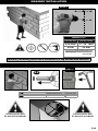
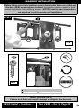
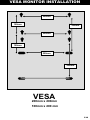
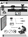
1
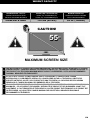
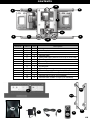
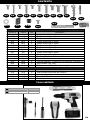
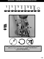
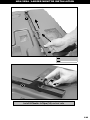
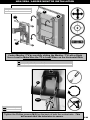
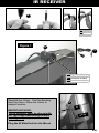
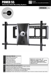
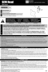
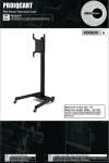
POWER 55 ULN # PN # UL10378 POWER 55 = L3-UL10378-CON-072208vB Motorized Wall Mounting System EN Instruction Manual ES Manual De Instrucciones FR Manuel D’instructions Maximum screen size: 55” Maximum weight 110 lbs - 50 KG CAUTION: DO NOT EXCEED MAXIMUM LISTED WEIGHT CAPACITY. SERIOUS INJURY OR PROPERTY DAMAGE MAY OCCUR! EN Images may differ from actual product ES El producto real puede variar respecto a la imagen mostrada. FR Le produit réel peut différer de l'illustration. WARNING! – ENGLISH WARNING! SEVERE PERSONAL INJURY AND PROPERTY DAMAGE CAN RESULT FROM IMPROPER INSTALLATION OR ASSEMBLY. READ THE FOLLOWING WARNINGS BEFORE BEGINNING. If you do not understand the instructions or have any concerns or questions, please contact a qualified installer. North America residents can contact OmniMount customer service at 800.668.6848 or [email protected]. Do not install or assemble if the product or hardware is damaged or missing. If you require replacement parts, contact OmniMount Customer Service at 800.668.6848 or [email protected]. International customers need to contact a local distributor for assistance. For wall mounted products: This product has been designed for use on a vertical wall constructed of wood studs or masonry (solid concrete). Wood studs being defined as a wall consisting of a minimum of 2 x 4 inch studs with a maximum of 24 inch stud spacing and a minimum of 16 inch stud spacing with a maximum of ¾ inch of wall covering (drywall, lath, plaster). If you don’t know your wall type, or for assistance with other surfaces (metal studs, solid block and brick), contact a qualified installer. For safe installation, the wall you are mounting to must support 4 times the weight of the total load. If not, the surface must be reinforced to meet this standard. The installer is responsible for verifying that the wall structure/surface and the anchors used in the installation will safely support the total load. This product is not designed to support the load of a CRT or flat screen television. Do not use this product for any application other than those specified by OmniMount. This product may contain moving parts. Use with caution. DO NOT EXCEED THE MAXIMUM WEIGHT CAPACITY FOR THIS PRODUCT. ¡ADVERTENCIA! – ESPAÑOL ¡ADVERTENCIA! LA INSTALACIÓN O EL MONTAJE INAPROPIADOS PUEDEN PROVOCAR LESIONES, DAÑOS MATERIALES O INCLUSO LA MUERTE. ANTES DE COMENZAR, LEA LAS SIGUIENTES ADVERTENCIAS. Si las instrucciones no le resultan claras o si tiene alguna duda o pregunta, comuníquese con un instalador calificado. Los residentes de América del Norte pueden comunicarse con el servicio de Atención al cliente de OmniMount al 800.668.6848 o por escrito a [email protected]. Si el producto o el hardware está dañado o no se le envió alguna pieza, no realice la instalación ni el montaje. Si necesita piezas de repuesto, comuníquese con el servicio de Atención al cliente de OmniMount al 800.668.6848 o por escrito a [email protected]. Los clientes internacionales deberán comunicarse con un distribuidor local para recibir asistencia. Produits s’installant au mur : Ce produit a été conçu pour une installation sur un mur vertical de maçonnerie (béton massif) ou construit sur une charpente en bois. Une charpente en bois est une structure murale constituée avec des pièces de colombage d’une épaisseur d’au moins 5 cm x 10 cm ayant un espacement de 41 cm à 61 cm et étant recouverte d’un revêtement d’une épaisseur d’au moins 19 mm (cloison sèche, lattes, plâtre). Si vous avez un doute sur la composition de votre mur ou si vous désirez des conseils concernant une autre surface (poutres métalliques, blocs massif et briques), contactez un installateur qualifié. Pour que l'installation soit sécuritaire, le mur d'installation doit pouvoir supporter 4 fois le poids de la charge appliquée. Si tel n'est pas le cas, la surface doit être renforcée en conséquence. L'installateur doit s'assurer que la structure/surface du mur d'installation et les chevilles d'ancrage utilisées peuvent supporter sans danger le poids de tous les équipements. Ce produit n’est pas conçu pour supporter le poids d’un téléviseur à écran cathodique ou à écran plat.No utilice este producto para ninguna aplicación que OmniMount no haya especificado. Este producto puede contener componentes móviles. Úselo con precaución. NO EXCEDA LA CAPACIDAD DE PESO MÁXIMA PARA ESTE PRODUCTO. AVERTISSEMENT! – FRANÇAIS AVERTISSEMENT! SI CE PRODUIT N’EST PAS CORRECTEMENT INSTALLÉ OU ASSEMBLÉ, IL RISQUE DE CAUSER DES BLESSURES GRAVES, VOIRE MORTELLES, AINSI QUE DES DOMMAGES MATÉRIELS IMPORTANTS. AVANT DE COMMENCER, LISEZ LES AVERTISSEMENTS SUIVANTS. Si vous ne comprenez pas les instructions, de même que si vous avez un doute ou des questions, veuillez contacter un installateur qualifié. Les personnes qui résident en Amérique du Nord peuvent contacter le service à la clientèle OmniMount au 800.668.6848 ou à [email protected]. Si vous découvrez que le produit est endommagé ou que des fixations sont manquantes ou endommagées, n’installez pas le produit. Si vous avez besoin de pièces de rechange, contactez le service à la clientèle OmniMount au 800.668.6848 ou à [email protected]. Les clients habitant hors de l’Amérique du Nord peuvent obtenir de l’aide auprès de leur distributeur local. Información acerca de los productos que se instalan en la pared: Este producto está diseñado para ser instalado en paredes verticales con paneles de madera o mampostería (hormigón). Se define a los paneles verticales como una pared que consiste de un mínimo de paneles de 5 cm x 10 cm con un espacio entre paneles máximo de 61 cm y un espacio mínimo entre paneles de 41 cm, con un máximo de cobertura de pared (hoja de yeso, listón, yeso) de 19 mm. Si no está seguro acerca del material de su pared o si desea obtener información sobre otras superficies (paneles de metal, bloques sólidos o ladrillo), comuníquese con un instalador calificado. Para realizar una instalación segura, la pared elegida debe ser capaz de soportar 4 veces el peso de la carga total. De lo contrario, deberá reforzar la superficie para que cumpla con este requisito. El instalador es el responsable de comprobar que la estructura/superficie de la pared y los tacos que se utilizan en la instalación soporten la carga total de manera segura. Este producto no está diseñado para soportar la carga de un televisor CTR o de pantalla plana. Ce produit ne doit pas être utilisé pour un usage autre que ceux spécifiés par OmniMount. Ce produit peut contenir des pièces mobiles. Veuillez l'utiliser avec prudence. NE DÉPASSEZ JAMAIS LA CAPACITÉ DE CHARGE MAXIMALE DE CE PRODUIT. P2 TABLE OF CONTENTS Maximum Weight P4 Hardware List P5-6 Symbol Key P7 Wood Stud Wall Installation P8-10 Solid Concrete Wall Installation P11-14 Slim TV Installation P15 VESA Monitor Installation P16-22 Non-VESA Monitor Installation P23-26 IR Receiver P27-28 Power P29 Cable Management P30 Remote Control Functions P31-33 Trouble Shooting P34 Warranty P35 P3 WEIGHT CAPACITY MAXIMUM WEIGHT CAPACITY MÁXIMA CAPACIDAD DE PESO CAPACITE DE CHARGE MAXIMALE POUNDS (LBS) / KILOGRAMS (KG) LIBRAS (LB) / KILOGRAMOS (KG) LIVRES (LB) / KILOGRAMMERS (KG) MAXIMUM SCREEN SIZE TAMAÑO DE PANTALLA MÁXIMO TAILLE D’ÉCRAN MAXIMALE COMPLETE UNIT 110 lbs (50 KG) 55 in. (140cm) CAUTION! 55” MAXIMUM SCREEN SIZE USE WITH PRODUCTS LARGER THAN THE MAXIMUM WEIGHT AND SIZE MAY RESULT IN INSTABILITY CAUSING POSSIBLE INJURY. USER MUST REMOVE TELEVISION OR OBJECT OFF THE BRACKET BEFORE ADJUSTING. IF EN THE PRODUCT IS A TELEVISION MAXIMUM WEIGHT CAPACITY SUPERSEDES / OUTPLACES RECOMMENDED DIAGONAL MEASURED TELEVISION SIZE!! EL USO CON EL PRODUCTOS MÁS GRANDE QUE EL PESO MÁXIMO Y TAMAÑO PUEDE CAUSAR INESTABILIDAD Y POSIBLEMENTE HERIDAS. EL USUARIO DEBE QUITAR LA TELEVISIÓN U OBJETO DEL ES SOPORTE ANTES DEL AJUSTE. SI EL PRODUCTO ES UNA TELEVISIÓN, LA CAPACIDAD DE PESO MÁXIMA REEMPLAZA EL TAMAÑO DIAGONAL RECOMENDADO DE LA TELEVISIÓN NE PAS UTILISER DES PRODUITS QUI SONT PLUS GRANDS DE LA CAPACITÉ DE CHARGE OU DES DIMENSIONS MAXIMALES – CELA POURRAIT PROVOQUER L’INSTABILITÉ DE PRODUIT ET DES BLESSURES. AVANT TOUT FR AJUSTEMENT, IL FAUT DÉMONTER LE TÉLÉVISEUR OU L’AUTRE PRODUIT ÉLÉCTRONIQUE. SI LE PRODUIT EST UN TÉLÉVISEUR, LA CAPACITÉ DE CHARGE MAXIMALE SE SUBSTITUE AU GRANDEUR DIAGONALE RECOMMANDÉ DU TÉLÉVISEUR. P4 CONTENTS 12 5 6 6 1 11 6 5 6 12 Contents - POWER 55 Pouch # Part # Qty 1 1 2 1 3 1 4 2 5 2 6 4 7 1 8 1 9 1 10 1 11 2 12 4 13 2 14 8 Description Wall Mount Wall Template Instruction Manual Vertical Rails Horizontal Rails (485mm End Cap to End Cap) End Caps & Screws Power Adapter Remote Control IR Receiver Mylar Sticker Tension Screws (Pre Installed) M6 x 7mm Horizontal Rail Screws (Pre Installed) Vertical Rail Covers (Pre Installed) Vertical Rails Plastic J Clips (Pre Installed) 14 2 13 10 7 9 8 4 P5 CONTENTS M-A M-B M-C M-D M-E M-F M-G M-H M-I M-J W-A W-C M-K M-L M-M Monitor Kit - POWER 55 Pouch # Part # Qty M-A M-A 4 M-B M-B 4 M-C M-C 4 M-D M-D 4 M-E M-E 4 M-F M-F 4 M-G M-G 4 M-H M-H 4 M-I M-I 4 M-J M-J 4 M-K M-K 4 M-L M-L 4 M-M M-M 4 M-N M-N 3 M-O M-O 2 Wall Kit - POWER 55 Pouch # Part # Qty W-A W-A 6 W-B W-B 6 W-C W-C 1 W-D W-D 1 W-B W-D M-O Description Philips screws M4 x 15mm Philips screws M4 x 45mm Philips screws M5 x 15mm Philips screws M5 x 45mm Philips screws M6 x 15mm Philips screws M6 X 20mm Philips screws M6 x 45mm Philips screws M8 x 15mm Philips screws M8 x 29mm Philips screws M8 x 45mm Washer OD 10mm ID 5mm x 1.0mm Square Washers Circular Spacers: 19.5mm OD x 8.25mm ID x 14.5mm H Wire Holders (Zip Ties) Philips screws M5 X 12 mm (Locking Screws) Description Wall Phillips Hex Screw M6 x 50mm Wall Anchors M6 Wood Drill Bit 1/8" Bubble Level TOOLS NEEDED EN ES FR Tools Needed Herramientas necesarias Outils requis Not included No se incluye Non inclus P6 SYMBOL KEY EN ES FR EN ES FR EN ES FR EN ES FR Drill Agujerear Percer Remove Retire Retirez EN ES FR Hammer Martillo Marteau EN ES FR Adjust Ajuste Ajustez Pencil Mark Marque con lápiz Marque de crayon EN ES FR Hand tighten Ajuste manual Serrer avec les doigts Find Center Position Encuentre la posición del centro Repérez la position centrale EN ES FR Phillips Screwdriver Destornillador Phillips Tournevis Phillips EN ES FR Level Nivel Niveau EN ES FR Tighten Fastener Ajuste el sujetador Serrez l'attache EN ES FR EN ES FR Optional Opcional Optionnel Cable Management Sistema de organización de cables Gestion des câbles EN ES FR Allen Wrench Llave Allen Clé hexagonale EN ES FR EN ES FR Caution Precaución Attention Loosen Fastener Afloje el sujetador Desserrez l'attache P7 WOOD STUD INSTALLATION STEP 1 STUD STEP 2 EN Find stud(s) and mark edge and center locations. ES Ubique el panel y marque las ubicaciones de los bordes y el centro. FR Repérez l'emplacement d'une poutre, puis marquez l'emplacement des bords et du centre de cette poutre. STUD CAUTION: Any Wood Stud Installation Greater than 16” Wide Must use a Dry Wall Anchor (Not Included) in the (B-Left) Section of the Wall Template. A B B Left Right 2 Stud # 1 Stud # 2 Adjust wall template (2) to accommodate width of studs. Refer to Wall Template (2) for further instructions. Stud #1 must be positioned in Section (A) P8 Stud #2 must be positioned in Section (B-Right). WOOD STUD INSTALLATION STEP 3 STEP 4 2 2 W-D Follow directions on the mounting template and use Bubble Level (W-D), secure to wall. Locate the middle mark of the Wall Template, use a Pin (not included) to secure the template into place. STEP 5 2 Good EN ES FR No Good Use wall template to mark mounting locations Use la guía de la pared para marcar el lugar donde se realizará la instalación Utilisez le gabarit mural pour marquer les emplacements de montage P9 WOOD STUD INSTALLATION STEP 6 STUD Wood Pilot Pilot Hole Size Pilot Drill Depth 1/8” inch 2 inch 4 mm 55 mm W-C EN ES FR STEP 7 Stud Drill pilot hole Realice el agujero piloto Percez le trou de guidage 5 Stud 2 W-A 1 X4 EN ES FR Tighten Fasteners Ajuste el sujetador Serrez l'attache Hand tools only Herramientas de mano solamente Outils manuels uniquement W-A P10 MASONRY INSTALLATION A B B Left Right 2 Place Wall Template (2) on solid concrete wall. A total of 6 Wall Anchors (W-B) and 6 Wall Screws (W-A) must be installed. Refer to Wall Template (2) for further instructions. Two Wall Anchors (W-B), Screws (W-A) must be installed in Section (A). Two Wall Anchors (W-B), Screws (W-A) must be installed in Section (B Left). Two Wall Anchors (W-B), Screws (W-A) must be installed in Section (B Right). Solid Concrete Only Do Not Drill Into Mortar Solid Concrete Only Do Not Drill Into Mortar P11 MASONRY INSTALLATION STEP 1 STEP 2 2 2 W-D Follow directions on the mounting template and use Bubble Level (W-D), secure to wall. Locate the middle mark of the Wall Template. STEP 3 2 Good EN ES FR No Good Use wall template to mark mounting locations Use la guía de la pared para marcar el lugar donde se realizará la instalación Utilisez le gabarit mural pour marquer les emplacements de montage For solid concrete wall installation 6 screws and anchors are required. P12 MASONRY INSTALLATION STEP 4 Masonry Pilot Pilot Hole Size Pilot Drill Length 5/16 inch 8 mm 2 – 1/8” inch 55 mm Not Included Masonry mounting must use a minimum of 6 lag screws and anchors STEP 5 W-B EN ES FR Concrete Wall Installation Instalación en pared de hormigón Installation sur mur en béton Solid Concrete Only Do Not Drill Into Mortar Drill pilot hole Realice el agujero guía Percez le trou de guidage Solid Concrete Concreto sólido Béton massif Solid Concrete Only Do Not Drill Into Mortar P13 MASONRY INSTALLATION Before lifting mount into position ensure that all pilot holes are drilled and Anchors (W-B) necessary are installed. Assistance may be needed to hold mount in position while installing screws. NOTE: 6 wall screws and anchors are required in solid concrete wall installation. STEP 6 5 1 X6 W-A 5 W-A X6 EN ES FR Tighten Fasteners Ajuste el sujetador Serrez l'attache Hand tools only Herramientas de mano solamente Outils manuels uniquement HAND TIGHTEN ONLY! Failure to do this may result / damage of stripping the Anchors. VESA Install – Continue… Non VESA – Go To Page 22 P14 READ!!! SLIM TV (6 cm thickness or less only) READ!!!!! Mount comes adjusted factory default suitable to fit most TV’s. This step is ONLY Slim Size Televisions with a depth of 0.24 in. (6 cm) or less. Check you TV installation Manual if your TV fits this criteria. You must adjust TV’s in this size range in order for the mount to function properly. If your TV does not fit this criteria, Skip to Page 16. 10 11 11 Remove perforated tabs to Access Tension Springs (11) on Front Monitor Plate. Remove the first screw to the right side of the Monitor Plate. Insert screwdriver or solid rod into slot holes on Right, applying pressure (IMPORTANT!). Assistance Highly Recommended: While applying pressure carefully unscrew second screw. SPRING TENSION IS HIGH. DO NOT LOOSE GRIP ON SCREWDRIVER / ROD! Once second screw is removed, slowly allow the tension spring to unwind upwards. Allow it uncoil until it rests. If in future a larger Monitor / TV are to be installed on Auto Wall Mount, Please Reverse Steps Above to adjust Tension to Springs. P15 VESA MONITOR INSTALLATION 200mm 100mm 200mm 200mm 100mm 200mm 200mm VESA 200mm x 200mm 100mm x 200 mm P16 VESA MONITOR INSTALLATION Punch out perforated lines to access horizontal rail screws (12). 12 X2 12 10 EN ES FR Loosen Half Way Afloje un poco Dévisser à moitié 10 1 X2 10 12 EN ES FR Loosen Half Way Afloje un poco Dévisser à moitié Loosen Horizontal Rail Screws (12). P17 VESA MONITOR INSTALLATION 5 1 6 5 6 6 5 EN ES FR Loosen Fastener Afloje el sujetador Desserrez l'attache 5 EN ES FR Remove Retire Retirez Remove the End Caps (6) from Horizontal Rails (5). The End Cap Sticker must be peeled back to access the screws. Discard End Cap Stickers. P18 VESA MONITOR INSTALLATION 5 1 5 EN ES FR Remove Retire Retirez 1 5 EN ES FR Remove Retire Retirez P19 VESA MONITOR INSTALLATION EN ES FR Attention: If screw "bottoms out" use washers (not included) to take up slack Atención: Si el tornillo hace tope, utilice arandelas (no se incluyen) para ajustarlo al máximo. Attention : Si les vis dépassent en dessous, utilisez des rondelles (non incluses) pour compenser **NOTE** ! WHEN INSTALLING FLAT PANEL TV DO NOT OVER TIGHTEN SCREWS AND MAKE SURE THAT SCREWS DO NOT BOTTOM OUT IN MOUNTING HOLES! CAUTION M-M M-A ~ M-K Hand Tighten Only! EN ES FR Use spacers for recessed mounting holes or to access A/V inputs Use los espaciadores para agujeros de montaje empotrados o para acceder a las entradas de A/V Utilisez les entretoises sur les trous de montage encastrés ou pour accéder aux entrées A/V P20 VESA MONITOR INSTALLATION M-A ~ M-K EN ES FR M-A M-B M-C M-D M-E Partially install Instalación parcial Installez partiellement M-F M-G M-H M-I M-J M-K Partially install top two Philips screws (M-A ~ M-J). Please use Washers (M-K) for screw sizes M4 and M5 (M-A ~ MD). Do Not Tighten EN ES FR Attach monitor using monitor hardware, M-A, M-B, etc… Coloque la pantalla utilizando los materiales de instalación de la pantalla, M-A, M-B, etc… Installer le moniteur avec les fixations de moniteur, M-A, M-B, etc… P21 VESA MONITOR INSTALLATION 1 1 EN ES FR Connect monitor and adapter to mount Conecte el monitor y el adaptador al soporte Connectez le moniteur et l'adaptateur sur le support 1 Step 1 1 1 Step 2 Step 3 Attach the TV to the Monitor Plate (1) with ONLY the top 2 screws partially installed through the Top 2 Keyhole Openings. Let Monitor Hang from the Top 2 Screws (Support Monitor Weight for safety while installing bottom 2 Screws), Secure the bottom 2 screws. M4 and M5 (M-A ~ MD) Screws Must use a Washer (M-K). Skip Pages 22-25 P22 NON-VESA / LARGER MONITOR INSTALLATION EN ES FR Attention: If screw "bottoms out" use washers (not included) to take up slack Atención: Si el tornillo hace tope, utilice arandelas (no se incluyen) para ajustarlo al máximo. Attention : Si les vis dépassent en dessous, utilisez des rondelles (non incluses) pour compenser **NOTE** ! WHEN INSTALLING FLAT PANEL TV DO NOT OVER TIGHTEN SCREWS AND MAKE SURE THAT SCREWS DO NOT BOTTOM OUT IN MOUNTING HOLES! CAUTION 4 4 M-L M-M M-A ~ M-K 1 M-L Hand Tighten Only! EN ES FR Use spacers for recessed mounting holes or to access A/V inputs Use los espaciadores para agujeros de montaje empotrados o para acceder a las entradas de A/V Utilisez les entretoises sur les trous de montage encastrés ou pour accéder aux entrées A/V P23 NON-VESA / LARGER MONITOR INSTALLATION M-A M-B M-C M-D M-E M-F M-G M-H M-I M-J M-K 4 M-A ~ M-K M-L M-L Insert Correct Size Screws (M-A ~ M-K) through the Square Washer (M-L) and Tighten into Television. HAND TIGHTEN ONLY. Do not Over tighten. Tighten all 4 Monitor Screws P24 NON-VESA / LARGER MONITOR INSTALLATION 4 13 EN ES FR Attach covers Coloque las cubiertas Fixez les caches 14 4 Install 8 Plastic J-Clips (14) vertical rails P25 NON-VESA / LARGER MONITOR INSTALLATION Hang with monitor attached Cuelgue con el monitor adherido. Accrochez avec le moniteur installé. 4 4 5 5 Center Monitor / TV by carefully sliding the Monitor / TV Left or Right Use a Level to Make Sure the TV is Level When on the Horizontal Rails EN ES FR This step may require two people Este paso podría requerir de dos personas. Il est possible que deux personnes soient nécessaires pour cette étape 4 5 M-O EN ES FR Tighten Fastener Ajuste el sujetador Serrez l'attache Tighten the Phillips screws (M-O) on the back of both the vertical rails. This will ensure that the television is secure. P26 IR RECEIVER 9 EN ES FR Figure 1 Remove Retire Retirez 9 9 EN Signal Receive ES Recepción de señal FR Réception du signal Separate the Velcro. Peel the Backing from the Velcro. Place the Velcro to desired location. 9 IR IMPORTANT NOTE: The IR Receiver Must be placed with the Top of the Head facing forward (see Figure 1) V DC12 Plug the IR Male End into the Mount P27 IR RECEIVER 7 22 M( ft) 8 9 20° 12 M (49 ft) 20° 7M (22 f t) IR (Infrared Receiver) Attach the IR receiver making sure nothing will obstruct the transmission from where the TV will be viewed. Instale el receptor IR asegurándose de que nada obstruirá la transmisión desde donde se verá el ES televisor Fixez le récepteur IR en vous assurant qu’aucun objet n’interfère avec la transmission infrarouge à FR partir de l’endroit d’où vous regarderez la télévision EN 9 The recommended mounting position is on top of TV. P28 POWER CORD WARNING!! DO NOT PLUG IN DC12V (POWER CORD) UNTIL ALL COMMUNICATION CABLES (IR RECIEVER, RS 232 [Not Included] ) ARE PLUGGED IN. 7 1 9 IR RS232 (Not Included) Consult a professional Installer DC12V 7 EN ES FR Insert Inserte Insérez Plug / Attach all communication Cables. Plug the DC12V (Power) into Mount. P29 CABLE MANAGEMENT 1 EN ES FR Route Cables Tienda los cables Installez les câbles M-N Secure Loose Cables with Zip Ties (M-N) EN ES FR Tighten Ajustar Serrer P30 REMOTE CONTROL PROGRAMMING (English) ATTENTION! Must set WALL DETECT RIGHT first. Failure to do this may result in poor performance of Wall Mount. If set LEFT WALL DETECT, please use the SETUP / RESET to clear memory SETUP: Push / Collapse the Wall Mount Flat against the Wall, Press and Hold for 5 seconds to set the home position (note: this also clears all memorized commands) RESET: Hold for 5 seconds to clear all commands and memorize HOME position. STEP 2 WALL DETECT LEFT Swivel to the closest to the Wall without the TV touching the Wall, leave about 1” (25mm) of space recommended, Hold down Wall Detect for 5 seconds till LED LIGHT color turns solid LED LIGHT Flashing LED: Transmitting Signal Solid Color LED: Memory Set or Cancelled TILT UP LEFT SWIVEL MEMORY 1: Hold for 5 Seconds until LED LIGHT color turns sold, memory is set Move to another desired location and repeat above step to memorize again. STEP 1 WALL DETECT RIGHT Swivel to the closest to the Wall without the TV touching the Wall, leave about 1” (25mm) of space recommended, Hold down Wall Detect for 5 seconds till LED LIGHT color turns solid RIGHT SWIVEL TILT DOWN 8 MEMORY 2: Hold for 5 Seconds until LED LIGHT color turns sold, memory is set Move to another desired location and repeat above step to memorize again. HOME This will bring the wall mount back to the wall of HOME position that user setup, if user needs to set a different Home position, please refer to SETUP button above for details. ATTENTION! Power Loss or interruption DOES NOT delete or clear the memory. User must use the SETUP / RESET button to clear memory. If Swivel too far RIGHT or LEFT and hits / makes contact with the wall, the unit will Stop after 2 seconds. P31 REMOTE CONTROL PROGRAMMING (Español ) ATENCION! Primero, se debe establecer la DETECCIÓN DE PARED a la DERECHA. Cualquier falla que pusiera ocurrir al realizar esto, podría resultar en un escaso rendimiento del Soporte de pared. Si establece la DETECCIÓN DE PARED a la IZQUIERDA, utilice SETUP / RESET (INSTALAR / REINICIAR) para vaciar la memoria. PASO 1 = INSTALACIÓN Vacíe la memoria y establezca la posición cero. Empuje y apoye la parte plana del soporte contra la pared a 0 grados. Presione y mantenga presionado por 5 segundos para establecer a la posición cero (nota: Esto también vacía todos los comandos memorizados). PASO 3 = INSTALACIÓN A LA IZQUIERDA DEL LÍMITE DE LA PARED Gire a la izquierda hacia la parte más cercana a la pared sin que el televisor toque la pared, deje un espacio de 1” (25 mm.) aproximadamente. Presione el Detector de pared por 5 segundos hasta que el color de la LUZ DEL LED permanezca ininterrumpido. LUZ DEL LED LED intermitente: Transmitiendo señal LED de color ininterrumpido: Memoria establecida o cancelada INCLINAR HACIA ARRIBA GIRAR BASE HACIA LA DERECHA GIRAR BASE HACIA LA IZQUIERDA PASO 4 = MEMORIA 1 (opcional): Gire / Incline hasta alcanzar la posición deseada y presione durante 5 segundos hasta que el color de la LUZ DEL LED permanezca ininterrumpido y la memoria esté establecida. PASO 2 = INSTALACIÓN A LA DERECHA DEL LÍMITE DE LA PARED Gire a la derecha hacia la parte más cercana a la pared sin que el televisor toque la pared, deje un espacio de 1” (25 mm.) aproximadamente. Presione el Detector de pared por 5 segundos hasta que el color de la LUZ DEL LED permanezca ininterrumpido. INCLINAR HACIA ABAJO 8 PASO 5 = MEMORIA 2 (opcional): Gire / Incline hasta alcanzar la posición deseada y presione durante 5 segundos hasta que el color de la LUZ DEL LED permanezca ininterrumpido y la memoria esté establecida CERO Esto llevará el soporte de pared hacia la pared, hacia atrás de la posición CERO que el usuario instaló. Si el usuario necesita establecer una posición cero diferente, remítase al botón de INSTALACIÓN que figura más arriba para obtener más información. ATENCION: La pérdida o interrupción de encendido NO elimina o vacía la memoria. El usuario debe utilizar el botón de SETUP / RESET (INSTALACIÓN / REINICIO) para vaciar la memoria. Si gira demasiado hacia la DERECHA o IZQUIERDA y golpea / toca la pared, la unidad se detendrá después de 2 segundos. P32 REMOTE CONTROL PROGRAMMING (Français) ATTENTION! Vous devez d’abord régler la DÉTECTION DU MUR DROIT. Si vous n’y parvenez pas le support pourrait ne pas fonctionner normalement. Pour régler ensuite la DÉTECTION DU MUR GAUCHE, vous devez d’abord utiliser la fonction SETUP / RESET (RÉGLAGE / RÉINITIALISATION) pour remettre la mémoire à zéro. ÉTAPE 1 = RÉGLAGE Remet la mémoire et l’unité TV maison à zéro. Poussez et dépliez le support parallèlement au mur, appuyez sue le bouton et maintenez-le enfoncé pendant 5 secondes pour déterminer la position de départ. (remarque : cette action efface également tous les réglages mémorisés auparavant). ÉTAPE 3 = RÉGLAGE DE DÉTECTION DU MUR GAUCHE Faites pivotez l’écran vers la gauche jusqu’à 25 mm du mur. Maintenez le bouton de détection de mur pendant 5 secondes jusqu’à ce que le voyant lumineux reste allumé de manière continue FAIRE PIVOTEZ VERS LA GAUCHE ÉTAPE 4 = MÉMOIRE 1 (facultatif): Pivotez / inclinez jusqu’à la position désirée puis maintenir pendant 5 secondes jusqu’à ce que le VOYANT LUMINEUX soit allumé de manière continue, la mémoire est maintenant réglée INCLINEZ VERS LE BAS VOYANT LUMINEUX Voyant clignotant: le signal se transmet Voyant allumé en permanence: Vous êtes en mode de réglage de la mémoire ou d’annulation INCLINEZ VERS LE HAUT ÉTAPE 2 = RÉGLAGE DE DÉTECTION DU MUR DROIT Faites pivotez l’écran vers la droite jusqu’à 25 mm du mur. Maintenez le bouton de détection de mur pendant 5 secondes jusqu’à ce que le voyant lumineux reste allumé de manière continue FAIRE PIVOTEZ VERS LA DROITE ÉTAPE 5 = MÉMOIRE 2 (facultatif): Pivotez / inclinez jusqu’à la position désirée puis maintenir pendant 5 secondes jusqu’à ce que le VOYANT LUMINEUX soit allumé de manière continue, la mémoire est maintenant réglée POSITION DE DÉPART Cette fonction ramène le support mural à la position de départ que vous avez déjà choisie, si vous désirez la changer, veuillez consulter les instructions détaillées de la fonction de RÉGLAGE décrites plus haut. ATTENTION: La mémoire n’est pas affectée par les pannes ou les interruptions de courant électrique. Vous devez utiliser le bouton SETUP / RESET (RÉGLAGE / RÉINITIALISATION) pour remettre la mémoire à zéro. Si l’écran pivote trop vers la GAUCHE ou la DROITE et se cogne ou entre en contact avec le mur, il s’arrêtera de lui-même au bout de 2 secondes. P33 TROUBLE SHOOTING Good No Good • Trouble Shooting • Unit Must be Level. If not level, TV will lean on one side and Operation Speed will be irregular. Longevity of mount use will be greatly reduced from not properly leveling the wall plate. • Wall Screws and Mounting Location • Wood Stud: Wall Mount Must have at least 4 Wall Point Location Mounted. Any Wood Stud Installation Greater than 16” Wide Must use a Dry Wall Anchor (Not Included) in the (B-Left) mounting Section - Refer to the Wall Template for additional Information. • Spring Tension • If the Tilt function is non-operational on your mount, check the depth of your TV. If the depth is less then 6 cm it is considered a Slim TV, and the Spring Tension screws must be removed (See page 15). • Communication / IR / Power Cord • The Power Cord must be installed last after you have already installed the Communication IR cable or RS 232 (Not Included). Installation order should be: IR Receiver or RS232 (Not Included) then Power Cord. • Initial Setup • User must set up the Right and Left Swivels Limits. User must setup the Right side FIRST before setting up the Left Side. P34 OMNIMOUNT PRODUCT WARRANTY ENGLISH This warranty applies to US Residents who purchase from an authorized OmniMount Dealer. OmniMount products are covered against defects in materials and workmanship for 1 years. OmniMount will repair or replace the defective component or product, at its sole discretion. To obtain warranty service, contact OmniMount customer service at 800.MOUNT.IT (800.668.6848) or [email protected]. You must supply a copy of your original receipt. If your product must be shipped to OmniMount for inspection, you will be responsible for the shipping charges. Replacement product shipped to you will be returned freight pre-paid. OmniMount disclaims any liability for modifications, improper installations, or installations over the specified weight range. To the maximum extent permitted by law, OmniMount disclaims any other warranties, expressed or implied, including warranties of fitness for a particular purpose and warranties of merchantability. OmniMount will not be liable for any damages arising out of the use of, or inability to use, OmniMount products. OmniMount bears no responsibility for incidental or consequential damages. This includes, but is not limited to, any labor charges for the repair of OmniMount products performed by anyone other than OmniMount. This warranty gives you specific legal rights, and you may also have other rights which vary from state to state. Specifications are subject to change without prior notice. ESPAÑOL Esta garantía tiene validez para los residentes estadounidenses que hayan realizado la compra en un distribuidor autorizado de OmniMount. Esta garantía cubre los productos OmniMount de los defectos de materiales y de mano de obra por un periodo de 1 años. OmniMount, a su exclusivo criterio, reparará o reemplazará el producto o componente defectuoso. Para obtener el servicio de garantía, comuníquese con el servicio de Atención al cliente de OmniMount. Llame al 800. MOUNT.IT (800.668.6848) o escríbanos a [email protected]. Deberá proporcionar el recibo original. Si fuera necesario enviar el producto a OmniMount para revisarlo, los gastos de envío correrán por su cuenta. El producto de reemplazo que se le envíe se le devolverá con los gastos de envío pagos. OmniMount no se hace responsable de modificaciones, instalaciones inadecuadas o instalaciones que superen el rango de peso especificado. En la medida en que la ley lo permita, OmniMount no se hace responsable de ninguna otra garantía, expresa o implícita, incluso las garantías de aptitud para un fin determinado o de comercialización. OmniMount no se hace responsable de ningún tipo de daños causados por el uso de los productos OmniMount o por el uso inapropiado de dichos productos. OmniMount no es responsable de los daños incidentales o emergentes. Dentro de éstos se incluyen todo tipo de gastos que pudieran surgir de las reparaciones de productos OmniMount que no se hayan realizado en OmniMount. Esta garantía le otorga derechos legales específicos. Es posible que además tenga otros derechos que varían según el estado. Las especificaciones están sujetas a cambios sin previo aviso. FRANÇAIS Cette garantie s’applique aux résidents des États-Unis qui achètent un produit OmniMount auprès d’un détaillant OmniMount autorisé. Les produits OmniMount sont garantis 1 ans contre les défauts de matériaux et de fabrication. OmniMount se chargera de réparer ou remplacer, à son entière discrétion, tout produit qui s’avérera défectueux. Pour obtenir une réparation sous garantie, contactez le service à la clientèle OmniMount au 800.MOUNT.IT (800.668.6848) ou à [email protected]. Vous devrez fournir une copie de votre reçu d’achat original. Si votre produit doit être expédié à un centre de réparation OmniMount pour y être inspecté, vous devrez payer les frais de port. Le produit de remplacement vous sera envoyé en port payé. OmniMount rejette toute responsabilité relativement à quelque problème pouvant être associé à une modification d’un produit, à une mauvaise installation ou à une installation ne respectant pas les limites de charge. Sous réserve des lois en vigueur, OmniMount réfute toute autre garantie expresse ou implicite, notamment toute garantie de commercialisation ou de convenance à un usage quelconque. OmniMount réfute toute responsabilité pour des dommages résultant de l’utilisation ou de l’impossibilité d’utiliser des produits OmniMount. OmniMount réfute également toute responsabilité pour quelque dommage accessoire ou indirect. Ceci s’applique notamment aux frais de main d’œuvre pour la réparation de produits OmniMount par une personne ne travaillant pas pour OmniMount. Cette garantie vous accorde des droits juridiques spécifiques, mais il est possible que vous ayez également d’autres droits selon votre lieu de résidence. Les spécifications sont susceptibles d’être modifiées sans préavis. P35 (EN) English (ES) Spanish (FR) French THANK YOU FOR PURCHASING AN OMNIMOUNT PRODUCT GRACIAS POR ADQUIRIR UN PRODUCTO DE OMNIMOUNT MERCI D’AVOIR ACHETÉ UN PRODUIT OMNIMOUNT OmniMount Systems, Inc. 8201 South 48th Street Phoenix, AZ 85044-5355 1-800-MOUNT-IT (1-800-668-6848) www.omnimount.com All trademarks are the property of their respective companies. OmniMount is a registered trademark of OmniMount Systems, Inc. © 2006 P36