1
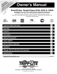
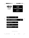
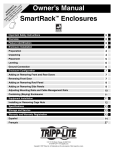
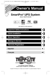
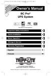
y
nt on for a Lite nty
a
i
p
r
ar at day rip rra
W istr ine to EE T m/wa
g nl FR .co
Reister owin aipplite
g o .tr
Re ce t ww
n !w
a
ch uct
od
r
p
Owner’s Manual
SmartPro®
Intelligent, Line-Interactive UPS Systems
Not suitable for mobile applications.
Important Safety Instructions
2
Quick Installation
3
Optional Installation
4
Basic Operation
5
Battery Replacement
8
Warranty Registration, Storage & Service
8
Español
10
Français
20
1111 W. 35th Street, Chicago, IL 60609 USA
Customer Support: (773) 869-1234 • www.tripplite.com
Copyright © 2008 Tripp Lite. All rights reserved. SmartPro® is a registered trademark of Tripp Lite.
Important Safety Instructions
SAVE THESE INSTRUCTIONS
This manual contains instructions and warnings that should be followed during the installation,
operation and storage of this product. Failure to heed these warnings will void your warranty.
UPS Location Warnings
• Install your UPS indoors, away from excess moisture or heat, conductive contaminants, dust or
direct sunlight.
• For best performance, keep the indoor temperature between between 32º F and 104º F (0º C
and 40º C).
• Leave adequate space around all sides of the UPS for proper ventilation.
• Do not mount unit with its front or rear panel facing down (at any angle). Mounting in this
manner will seriously inhibit the unit's internal cooling, eventually causing product damage not
covered under warranty.
UPS Connection Warnings
• Connect your UPS directly to a properly grounded AC power outlet. Do not plug the UPS into
itself; this will damage the UPS.
• Do not modify the plug, and do not use an adapter that would eliminate the ground connection.
• Do not use extension cords to connect the UPS to an AC outlet.
• If the UPS receives power from a motor-powered AC generator, the generator must provide
clean, filtered, computer-grade output.
Equipment Connection Warnings
• Use of this equipment in life support applications where failure of this equipment can
reasonably be expected to cause the failure of the life support equipment or to significantly
affect its safety or effectiveness is not recommended. Do not use this equipment in the
presence of a flammable anesthetic mixture with air, oxygen or nitrous oxide.
• Do not connect surge suppressors or extension cords to the output of your UPS. This might
damage the UPS and will void the surge suppressor and UPS warranties.
Battery Warnings
• Batteries can present a risk of electrical shock and burn from high short-circuit current. Observe
proper precautions. There are no user-serviceable parts inside the UPS. Do not open the UPS
except to perform battery replacement. Do not open batteries. Do not short or bridge the battery
terminals with any object. Unplug and turn off the UPS before performing battery replacement.
Use tools with insulated handles. Battery replacement should be performed only by authorized
service personnel using the same number and type of batteries (Sealed Lead-Acid). Do not
dispose of the batteries in a fire. The batteries are recyclable. Refer to your local codes for
disposal requirements or in the USA only call 1-800-SAV-LEAD or 1-800-8-BATTERY
(1-800-822-8837) or visit www.rbrc.com for recycling information. Tripp Lite offers a complete
line of UPS System Replacement Battery Cartridges (R.B.C.).Visit Tripp Lite on the Web at
www.tripplite.com/support/ battery/index.cfm to locate the specific replacement battery for your
UPS.
2
Quick Installation
Note: The illustrations may differ somewhat from
your model.
1 (Select Models) With the UPS
disconnected from utility power, use
a small tool to set the Voltage Dip
Switch to match your input voltage.
(All models are preset to the 120V
setting.)
1
2 Plug the UPS into an outlet on a
dedicated circuit.
NOTE! after you plug the UPS into a live AC
outlet, the UPS will automatically charge its
batteries,* but will not supply power to its outlets
until it is turned ON.
2
* The BATTERY CHARGE LED will be the only LED illuminated
3 Plug your equipment into the UPS.
Note: Your UPS is designed to support electronic
equipment only. You will overload the UPS if the
total VA rating for all equipment connected
exceeds the UPS Output Capacity. To find your
equipment's VA ratings, look on the nameplates. If
the equipment is listed in amps, multiply the
number of amps by 120 to determine VA.
(Example: 1 amp × 120 = 120 VA). If you are
unsure if you have overloaded the UPS, see
“OUTPUT LOAD LEVEL” LED description.
3
A
4
4 Turn the UPS ON.
Press and hold the “STANDBY” button A for
one second. The alarm will beep once briefly after
one second has passed. Release the button.
3
Optional Installation
Basic Operation
These connections are optional. Your UPS will function properly without these connections.
“STANDBY” Button
• To turn the UPS ON: with the UPS plugged into a live AC wall outlet,*
press and hold the STANDBY button for about one second.** Release
the button. If utility power is absent, you can "cold-start" the UPS (i.e.:
turn it ON and supply power for a limited time from its batteries***) by
pressing and holding the STANDBY button for about two seconds.**
• To turn the UPS OFF: with the UPS ON and receiving utility power,
press and hold the STANDBY button for one second.** Then unplug the
UPS from the wall outlet. The UPS will be completely OFF.
1 USB and RS-232 Serial
Communications
Use the included USB cable 1a and/or DB9 serial
cable 1b to connect the communication port on
your computer to the communication port of your
UPS. Install on your computer the Tripp Lite
PowerAlert Software appropriate for your
computer’s operating system. Consult the
PowerAlert manual for more information.
1a
* After you plug the UPS into a live AC outlet, the UPS will automatically charge its batteries,
but will not supply power to its outlets until it is turned ON. ** The alarm will beep once
briefly after the indicated interval has passed. *** If fully charged.
2 Telephone/Network Protection Jacks
Your UPS has jacks that protect against surges over
a telephone line or a network data line. Using
telephone or network data cables, connect your wall
jack to the UPS jack marked “IN.” Connect your
equipment to the UPS jack marked “OUT.” Make
sure the equipment you connect to the UPS jacks is
also protected against surges on the AC line.
“MUTE/TEST” Button
• To Silence (or “Mute”) UPS Alarms: briefly press and release the
MUTE/TEST button. Note: Continuous alarms (warning you to
immediately shut down connected equipment) cannot be silenced.
• To Run a Self-Test: with your UPS plugged in and turned ON, press and
hold the MUTE/TEST button for two seconds. Continue holding the
button until the alarm beeps several times and the UPS performs a self
test. See “Results of a Self-Test” below. Note: you can leave connected
equipment on during a self-test. Your UPS, however, will not perform a
self-test if it is not turned ON (see “STANDBY” Button description).
1b
3 External Battery Connection
Your UPS comes with a robust internal battery
system; external batteries are needed only to
extend runtime. Adding external batteries will
increase recharge time as well as runtime.
Warning: Do not connect or disconnect
battery packs when the UPS is running on
battery power.
4
CAUTION! Do not unplug your UPS to test its batteries. this will
remove safe electrical grounding and may introduce a damaging surge
into your network connections.
2
The illustration shows the location of the
External Battery Connector A , where you will
insert the battery pack cable. Complete
installation instructions for your battery pack
appear in the battery pack owner's manual. Make
sure that cables are fully inserted into their
connectors. Small sparks may result during
battery connection; this is normal.
Buttons
A
3
Results of a Self-Test: The test will last approximately 10 seconds as the
UPS switches to battery to test its load capacity and battery charge. The
“POWER” LED will be flashing and the “OUTPUT LOAD LEVEL” and
“BATTERY CHARGE” LEDs will be lit and the UPS alarm will sound.
• If the “OUTPUT LOAD LEVEL” LED remains lit red and the alarm
continues to sound after the test, the UPS outlets are overloaded. To clear
the overload, unplug some of your equipment and run the self test
repeatedly until the “OUTPUT LOAD LEVEL” LED is no longer lit red
and the alarm is no longer sounding.
CAUTION! Any overload that is not corrected by the user immediately
following a self-test may cause the UPS to shut down and cease
supplying output power in the event of a blackout or severe brownout.
• If the “BATTERY WARNING” LED remains lit and the alarm continues
to sound after the test, the UPS batteries need to be recharged or replaced.
Allow the UPS to recharge continuously for 12 hours, and repeat the selftest. If the LED remains lit, contact Tripp Lite for service. If your UPS
requires battery replacement, visit www.tripplite.com/support/battery/
index.cfm to locate the specific Tripp Lite replacement battery for your UPS.
5
Basic Operation
Basic Operation
(continued)
Indicator Lights
(continued)
Other UPS Features
All Indicator Light descriptions apply when the UPS is plugged into a wall outlet and
turned ON.
“POWER” LED: This green LED lights continuously when the UPS is
ON and supplying connected equipment with AC power from a utility
source. The LED flashes and an alarm sounds (4 short beeps followed by
a pause) to indicate the UPS is operating from its internal batteries during
a blackout or severe brownout. If the blackout or severe brownout is
prolonged, you should save files and shut down your equipment since
internal battery power will eventually be depleted. See “BATTERY
CHARGE” LED description below.
“VOLTAGE CORRECTION” LED: This green LED lights
continuously whenever the UPS is automatically correcting high or low
AC voltage on the utility line without the assistance of battery power. The
UPS will also emit a slight clicking noise. These are normal, automatic
operations of the UPS; no action is required on your part.
“OUTPUT LOAD LEVEL” LEDs: These multicolored LEDs indicate
the approximate electrical load of equipment connected to the UPS outlets:
green (light load), yellow (medium load) and red (overload). If the red LED
is either illuminated continuously or flashing, clear the overload
immediately by unplugging some of your equipment from the outlets until
the yellow or green LED illuminates. CAUTION! Any overload that is not
corrected by the user immediately may cause the UPS to shut down and
cease supplying output power in the event of a blackout or severe brownout.
“BATTERY CHARGE” LEDs: When the UPS is operating from utility
power, these LEDs indicates the approximate charge state of the UPS
internal batteries: red indicates the batteries are beginning to charge;
yellow indicates the batteries are roughly midway through charging; and
green indicates the batteries are fully charged. When the UPS is operating
from battery power during a blackout or severe brownout, these multicolor
LEDs indicate the approximate amount of energy (ultimately affecting
runtime) that the UPS batteries will provide: red indicates a low level of
energy; yellow indicates a medium level of energy; and green indicates a
high level of energy. Since the runtime performance of all UPS batteries
will gradually deplete over time, it is recommended that you periodically
perform a self-test (see “MUTE/TEST” Button description) to determine
the energy level of your UPS batteries BEFORE a blackout or severe
brownout occurs. During a prolonged blackout or severe brownout, you
should save files and shut down your equipment since battery power will
eventually be depleted. When the red LED illuminates and an alarm
sounds continuously, this indicates that the UPS batteries are nearly out of
power and UPS shutdown is imminent.
“BATTERY WARNING” LED: this LED lights yellow and an alarm
sounds intermittently after you initiate a self test (See “MUTE/TEST”
Button description) to indicate the UPS batteries need to be recharged or
replaced. Allow the UPS to recharge continuously for 12 hours, and repeat
the self-test. If the LED continues to light, contact Tripp Lite for service.
If your UPS requires battery replacement, visit www.tripplite.com.
“SITE WIRING FAULT” LED: This yellow LED will be lit if the UPS
detects a problem with the wiring of the AC outlet you connect it to. If this
occurs, have the outlet inspected by a qualified electrician. Note that while
the UPS will detect many common wiring faults, including a missing
ground, reversed polarity and overloaded neutral circuits, it cannot detect
every conceivable wiring problem.
6
Voltage DIP Switch (Select Models): This switch enables you to set the
UPS to match actual input voltage. If the Voltage DIP Switch is set above
or below the actual input voltage, the UPS will treat the input as a
continuous overvoltage or undervoltage condition, and will automatically
adjust input voltage to match the Voltage Dip Switch setting. This will
cause constant, unnecessary wear on the UPS system. Note: The Voltage
DIP Switch must be set with the UPS turned OFF and disconnected
from utility power. If the switch is set while the UPS is connected to
utility power, the setting will not take effect.
NEMA 5-15R
USB
RS-232 (DB9)
AC Outlets: These outlets provide your connected equipment with AC
line power during normal operation and battery power during power
outages. The UPS protects equipment connected to these outlets against
damaging surges and line noise.
Communication Ports (USB and RS-232): These ports connect your
UPS to a workstation or server. Use with Tripp Lite's PowerAlert Software
and included cables to enable your computer to automatically save open
files and shut down equipment during a blackout. Also use PowerAlert
Software to monitor a wide variety of AC line power and UPS operating
conditions. Consult your PowerAlert Software manual or contact Tripp
Lite Customer Support for more information. See “USB Communications”
and “RS-232 Serial Communications” in the “Optional Installation”
section for installation instructions.
Telephone/Network Protection Jacks: These RJ45 jacks protect your
equipment against surges over a telephone/network data line. Connecting
your equipment to these jacks is optional. Your UPS will work properly
without this connection.
Accessory Slot: Remove the small cover panel from this slot to install
optional accessories to remotely monitor and control your UPS. Refer to
your accessory’s manual for installation instructions. Contact Tripp Lite
Customer Support at (773) 869-1234 for more information, including a list
of available SNMP, networking management and connectivity products.
Fan: The fan cools the internal components.
Input Breaker (Select Models): Protect your electrical equipment from
overcurrent draw from the UPS load. If this breaker trips, remove some of
the load, then reset it by pressing the breaker in.
7
Battery Replacement
1
Battery Replacement Door: Under normal conditions, the original
battery in your UPS will last several years. Battery replacement should be
performed only by qualified service personnel. Refer to “Battery
Warnings” in the Safety section. Should your UPS require battery
replacement, visit Tripp Lite on the Web at www.tripplite.com/support/
battery/index.cfm to locate the specific replacement battery for your UPS.
1
2
Storage & Service
Carefully pull the front panel away from the UPS.
Place front panel on top of the unit. Remove the battery support bar.
2
Remove old batteries.
Carefully pull the batteries from the UPS and disconnect them.
3
Connect new batteries.
Connect the new batteries in exactly the same manner as the old
ones: positive (red) connectors together and negative (black)
connectors together. Carefully push batteries back into the UPS.
3
4
Reassemble UPS.
Reinstall the battery support bar and replace the front panel.
Warranty Registration
Visit www.tripplite.com/warranty today to register the warranty for your new Tripp Lite product.
You'll be automatically entered into a drawing for a chance to win a FREE Tripp Lite product!*
* No purchase necessary. Void where prohibited. Some restrictions apply. See website for details.
(continued)
Service
Before returning your UPS for service, follow these steps:
1. Review the installation and operation instructions in this manual to ensure that the service
problem does not originate from a misreading of the instructions.
2. If the problem continues, do not contact or return the UPS to the dealer. Instead, call Tripp
Lite at (773) 869-1233. A service technician will ask for the UPS model number, serial number
and purchase date and will attempt to correct the problem over the phone.
3. If the problem requires service, the technician will issue you a Returned Material
Authorization (RMA) number, which is required for service. If you require packaging, the
technician can arrange to send you proper packaging. Securely pack the UPS to avoid damage
during shipping. Do not use Styrofoam beads for packaging. Any damages (direct, indirect,
special, incidental or consequential) to the UPS incurred during shipment to Tripp Lite or an
authorized Tripp Lite service center is not covered under warranty. UPS Systems shipped to
Tripp Lite or an authorized Tripp Lite service center must have transportation charges prepaid.
Mark the RMA number on the outside of the package. If the UPS System is within the 2-year
warranty period, enclose a copy of your sales receipt. Return the UPS for service using an
insured carrier to the address given to you by the Tripp Lite service technician.
FCC Notice, Class B (For devices with FCC logo.)
This device complies with part 15 of the FCC Rules. Operation is subject to the following two conditions: (1) This device may not cause
harmful interference, and (2) this device must accept any interference received, including interference that may cause undesired operation.
Note: This equipment has been tested and found to comply with the limits for a Class B digital device, pursuant to part 15 of the FCC Rules.
These limits are designed to provide reasonable protection against harmful interference in a residential installation. This equipment
generates, uses and can radiate radio frequency energy and, if not installed and used in accordance with the instructions, may cause harmful
interference to radio communications. However, there is no guarantee that interference will not occur in a particular installation. If this
equipment does cause harmful interference to radio or television reception, which can be determined by turning the equipment off and on,
the user is encouraged to try to correct the interference by one or more of the following measures:
• Reorient or relocate the receiving antenna.
• Increase the separation between the equipment and receiver.
• Connect the equipment into an outlet on a circuit different from that to which the receiver is connected.
• Consult the dealer or an experienced radio/TV technician for help.
Storage & Service
Any changes or modifications to this equipment not expressly approved by Tripp Lite could void the user's authority to operate this equipment.
FCC Notice, Class A (For devices without FCC logo.)
This device complies with part 15 of the FCC Rules. Operation is subject to the following two conditions: (1) This device may not cause
harmful interference, and (2) this device must accept any interference received, including interference that may cause undesired operation.
Storage
CAUTION! Your UPS has an internal power source. Its outlets may still deliver current, even
after the UPS is unplugged, until the UPS is completely turned OFF (deactivated). Before
storing your UPS, turn it completely OFF: with the UPS ON and receiving utility power, press
and hold the STANDBY button for one second (an alarm will beep once briefly after the interval
has passed); then, unplug the UPS from the wall outlet. If you store your UPS for an extended
period of time, recharge the UPS batteries once every three months: plug the UPS into a wall
outlet; allow it to charge for 4 to 6 hours; and then unplug it and place it back in storage. Note:
after you plug the UPS in, it will automatically begin charging its batteries; however, it will not
supply power to its outlets (see Quick Installation section). If you leave your UPS batteries
discharged for an extended period of time, they will suffer a permanent loss of capacity.
Note: This equipment has been tested and found to comply with the limits for a Class A digital device, pursuant to part 15 of the FCC Rules.
These limits are designed to provide reasonable protection against harmful interference when the equipment is operated in a commercial
environment. This equipment generates, uses, and can radiate radio frequency energy and, if not installed and used in accordance with the
instruction manual, may cause harmful interference to radio communications. Operation of this equipment in a residential area is likely to
cause harmful interference in which case the user will be required to correct the interference at his own expense. The user must use shielded
cables and connectors with this equipment. Any changes or modifications to this equipment not expressly approved by Tripp Lite could void
the user's authority to operate this equipment.
FCC Part 68 Notice (United States Only)
If your Modem/Fax Protection causes harm to the telephone network, the telephone company may temporarily discontinue your service. If
possible, they will notify you in advance. If advance notice isn't practical, you will be notified as soon as possible. You will be advised of your
right to file a complaint with the FCC. Your telephone company may make changes in its facilities, equipment, operations or procedures that
could affect the proper operation of your equipment. If it does, you will be given advance notice to give you an opportunity to maintain
uninterrupted service. If you experience trouble with this equipment's Modem/Fax Protection, please call Tripp Lite Technical Support at (773)
869-1234 for repair/warranty information. The telephone company may ask you to disconnect this equipment from the network until the
problem has been corrected or you are sure the equipment is not malfunctioning. There are no repairs that can be made by the customer to
the Modem/Fax Protection. This equipment may not be used on coin service provided by the telephone company. Connection to party lines
is subject to state tariffs. (Contact your state public utility commission or corporation commission for information.)
Regulatory Compliance Identification Numbers
For the purpose of regulatory compliance certifications and identification, your Tripp Lite product
has been assigned a unique series number. The series number can be found on the product
nameplate label, along with all required approval markings and information. When requesting
compliance information for this product, always refer to the series number. The series number
should not be confused with the marking name or model number of the product.
Tripp Lite follows a policy of continuous improvement. Product specifications are subject to change
without notice.
Made in China.
8
9
Note on Labeling
Two symbols are used on
the label.
V~ : AC Voltage
V : DC Voltage
1111 W. 35th Street, Chicago, IL 60609 USA
773.869.1234 (USA) • 773.869.1212 (International)
www.tripplite.com
2009XXXXX 93-2773_EN