1
Operation
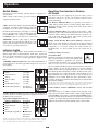
Switch Modes
Switch between the following operating modes as appropriate to
your situation:
“ON”: Switch to this setting to provide connected
equipment with AC power.
REMOTE
“OFF”: Switch to this setting to shut down the Inverter
completely, preventing it from drawing power from
the batteries. Use this switch to automatically reset
the unit if it shuts down due to low battery or overload. REMOTE
Use an optional remote control module (Tripp Lite
model APSRM4, sold separately or included with
PV3000HF models) to reset unit due to overload only.
“REMOTE”: Switch to this setting to remotely
monitor and control the Inverter with the use of an
optional remote module. See remote module’s owner’s manual for operating instructions.
REMOTE
OFF
ON
OFF
ON
OFF
Overload Shutdown Reset: Set operating mode switch to “OFF”
and remove some of the connected electrical load (ie: turn off some
of the AC devices drawing power which may have caused the overload of the unit). Wait one minute, then switch operating mode
switch back to either “REMOTE” or “ON.”
Output Circuit Breaker Reset (Select Models): Alternatively,
check output circuit breaker(s) on the unit's front panel. If tripped,
remove some of the electrical load, then wait one minute to allow
components to cool before resetting the circuit breaker. See
Troubleshooting for other possible reasons AC output may be
absent.
ON
Your Inverter is equipped with a simple, intuitive, user-friendly set of
indicator lights. These easily-remembered “traffic light” signals will
allow you, shortly after first use, to tell at a glance the charge condition
of your batteries, as well as ascertain approximate equipment load
level.
“BATTERY” Indicator Lights: These three lights will illuminate in
several sequences to show the approximate charge level of your connected battery:
1
2
3
4
5
6
Set Battery Charge Conserver
LOAD
SENSE
(Load Sense) Dial
In order to save battery power, the Inverter automatically
LESSER
shuts off in the absence of any power demand from GREATER
LOAD
LOAD
ON
ON
connected equipment or appliances (the electrical
load). When the unit detects a load, it automatically
turns on. Users may choose the minimum load the Inverter will
detect by adjusting the Battery Charge Conserver Dial (see diagram).
Using a small tool, turn the dial clockwise to lower the minimum
load that will be detected, causing the Inverter to turn on for smaller
loads. When the dial is turned fully clockwise, the Inverter will operate
even when there is no load. Turn the dial counterclockwise to set a
higher minimum load, causing the Inverter to stay off until the new
minimum load is reached. When the dial is turned fully counterclockwise, the Inverter will turn on when it detects any load greater than
approximately 150 Watts.
Note: The factory setting for the dial is fully clockwise. However, based on the threshold load to which
you’d like the Inverter to respond, you should adjust the dial counterclockwise to reduce its sensitivity
until the Inverter is active only when connected equipment or appliances are actually in use.
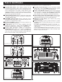
Connect Remote Control—OPTIONAL
7
1
4
(included with PV3000HF/
PV3000GFCI)
“LOAD” Indicator Lights: These three lights will illuminate in
several sequences to show the approximate equipment load level on
the Inverter’s AC receptacles.
Approximate Equipment Load Level
Indicator Illuminated Load Level
1 Green
0%-50%
2 Green & Yellow
51%-75%
3 Yellow
76%-90%
4 Red
> 90%
5 Flashing Red (quickly)** OVERLOAD
(Inverter has
shutdown)
Your Inverter may cease supplying AC power in order to protect
itself from overload or to protect your electrical system. To restore
normal functioning:
Low Battery Shutdown Reset: Set operating mode switch to
“OFF” and run vehicle engine to recharge battery. When battery is
adequately charged, switch operating mode switch back to either
“REMOTE” or “ON.”
Indicator Lights
Approximate Battery Charge Level†
Indicator Illuminated Battery Capacity
1 Green
91%–Full
2 Green & Yellow
81%–90%
3 Yellow
61%–80%
4 Yellow & Red
41%–60%
5 Red
21%–40%
6 Flashing Red (slowly)*
1%–20%
7 Flashing Red (quickly)** 0% (Inverter
has shutdown)
Resetting Your Inverter to Restore
AC Power
2
All models feature an 8-conductor telephone style receptacle on the
front panel for use with an optional remote control module (Tripp Lite
model APSRM4, sold separately or included with PV3000HF models).
The remote module allows the Inverter to be mounted in a compartment
or cabinet out of sight, while operated conveniently from your vehicle’s
dashboard. See instructions packed with the remote control module.
3
5
† Charge levels listed are approximate. Actual conditions vary depending on battery condition
and load. * Approximately ½ second on, ½ second off. ** Approximately ¼ second on, ¼ second
off. See “Resetting Your Inverter to Restore AC Power” to reset after Inverter shut down.
4PV