1
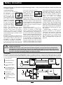
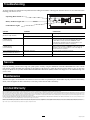
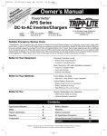
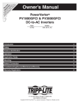
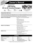
Owner’s Manual
PowerVerter
PV1000HF, PV1800HF & PV3000HF
DC-to-AC Inverters
®
Input
12 VDC
Output
120V, 60 Hz. AC
1111 W. 35th Street, Chicago, IL 60609 USA
Customer Support: (773) 869-1234
www.tripplite.com
GROUND
PV1000HF
PV1800HF
PV3000HF
Reliable AC Power Wherever You Need It!
• Automatic Overload Protection
Congratulations! You’ve purchased the most advanced, feature-rich
Inverter designed as a mobile energy source for your vehicle.
PowerVerter Inverters efficiently convert DC (battery) power into
120V AC (household) power, allowing you to use equipment you
commonly use at home—appliances, entertainment systems, computers,
power tools and more—while cruising the open road or out on the
open water. PowerVerter Inverters, through a high-efficiency conversion
process and a charge conservation setting, draw the highest level of
performance from your batteries without overtaxing them, lengthening
their service life. An automatic low battery shutdown feature ensures
you'll always have plenty of power for starting purposes.
• Automatic “Battery-Saver” Low Voltage Shutdown
• High Efficiency DC-to-AC Inversion
• Multi-Function Lights & Switches
• Optional Remote Control Capability
(Module included with PV3000HF)
Register on-line today for a chance to win a FREE Tripp Lite product!
www.tripplite.com/warranty
Contents
Specifications
2
Application Guide
5
Safety
2
Mounting
6
Feature Identification
3
Battery Connection
7
Operation
4
Troubleshooting/Service/
Maintenance/Warranty
8
Copyright © 2004. PowerVerter® is a registered trademark of Tripp Lite. All rights reserved.
(back page)
Specifications
MODEL NUMBER:
PV1000HF
PV1800HF
Minimum Recommended Cable Sizing Chart†
PV3000HF
Continuous Power (@ 20° C):*
1000 Watts
1800 Watts
3000 Watts
Double Boost™ Peak Surge Power:* 2000 Watts
3600 Watts
6000 Watts
DC Input Volts (Nominal):
12 VDC
12 VDC
12 VDC
DC Input Voltage Range:
10 - 15 VDC
10 - 15 VDC
10.5 - 15 VDC
DC Input Connection:
User Supplied Cables User Supplied Cables User Supplied Cables
Output Volts (Nominal):
120 VAC
120 VAC
120 VAC
Output Frequency (Nominal):
60 Hz, ± 0.5%
60 Hz, ± 0.5%
60 Hz, ± 0.5%
Efficiency:
Up to 94%
Up to 94%
Up to 94%
Output Waveform:
Modified Sine Wave Modified Sine Wave Modified Sine Wave
* DoubleBoost duration (instantaneous). Actual output depends on battery age, battery charge
level and ambient temperature. The policy of Tripp Lite is one of continuous improvement.
Specifications are subject to change without notice.
Always loosely twist each pair of cables (one positive and one negative) together.
Use in conjunction with DC wiring connection instructions in the Battery Connection section.
Using 4 conductors is recommended (but not required) to obtain
maximum output power from PV3000HF models.
Wire Gauge
2 Conductors
4 Conductors
(all models)
Watts
(PV3000HF only)
6
4
2
0
00
Twin 00
500
15 ft
25 ft
39 ft
62 ft
79 ft
158 ft
700
11 ft
18 ft
28 ft
44 ft
56 ft
112 ft
1000
N/R
12 ft
20 ft
31 ft
39 ft
78 ft
2000
N/R
N/R
N/R
16 ft
20 ft
40 ft
2400
N/R
N/R
N/R
13 ft
16 ft
32 ft
3000
N/R
N/R
N/R
10 ft
13 ft
26 ft
† N/R = Not Recommended. NOTE: Acceptable power is directly related to cable length (i.e. - the shorter the cable, the better the performance)
Tripp Lite Inverters include a Battery Charge Conserver (Load Sense) Control which saves battery power by allowing users to
set the minimum load level at which the unit’s inverter turns on. Users can significantly reduce the No Load DC Input Current to
a very low amperage power level with the use of this control.
Important Safety Instructions
SAVE THESE INSTRUCTIONS!
This manual contains important instructions and warnings that should be followed during the installation, operation and storage of all Tripp Lite Inverters.
Location Warnings
• Install your Inverter in a location or compartment in your vehicle that minimizes exposure to heat, dust, direct sunlight and moisture.
Flooding the unit with water will cause it to short circuit and could cause personal injury due to electric shock.
• Leave a minimum of 2" clearance at front and back of the Inverter for proper ventilation. To avoid overheating the Inverter, any
compartment that contains the Inverter must be properly ventilated with adequate outside air flow. The heavier the load of connected
equipment, the more heat will be generated by the unit.
• Do not install the Inverter directly near magnetic storage media, as this may result in data corruption.
• Do not install near flammable materials, fuel or chemicals.
Battery Connection Warnings
• Multiple battery systems must be comprised of batteries of identical voltage, age, amp-hour capacity and type.
• Because explosive hydrogen gas can accumulate near batteries if they are not kept well ventilated, your batteries should not be
installed in a “dead air” compartment. Ideally, any compartment would have some ventilation to outside air.
• Sparks may result during final battery connection. Always observe proper polarity as batteries are connected.
• Do not allow objects to contact the DC input terminals. Do not short or bridge these terminals together. Serious personal injury
or property damage could result.
Equipment Connection Warnings
• Do not use a Tripp Lite Inverter in life support or healthcare applications where a malfunction or failure of a Tripp Lite
Inverter could cause failure of, or significantly alter the performance of, a life support device or medical equipment.
• You may experience uneven performance results if you connect a surge suppressor, line conditioner or UPS system to the output of
the Inverter.
Operation Warnings
• Your Inverter does not require routine maintenance.
• Potentially lethal voltages exist within the Inverter as long as the battery supply is connected. During any service work, the battery
supply should therefore be disconnected.
• Do not connect or disconnect batteries while the Inverter is operating from the battery supply. Dangerous arcing may result.
2PV
Feature Identification
Identify the premium features on your specific model and quickly locate instructions on how to maximize their use.
1
2
Operating Mode Switch: controls Inverter operation. Set this
3-position rocker switch to “ON” to have your Inverter provide
connected equipment with AC power by converting DC power
from an attached battery. Set switch to “OFF” when not using
connected equipment to prevent battery drain. Set switch to
“REMOTE” to remotely monitor and control the Inverter with
the use of an optional remote module.
“LOAD” Indicator Lights: intuitive “traffic light” signals show
approximate equipment load level. See page 4 for instructions
on reading indicator lights.
3
“BATTERY” Indicator Lights: intuitive “traffic light” signals
show approximate charge level of your battery. See page 4 for
instructions on reading indicator lights.
4
DC Power Terminals: connect to your battery terminals. See
page 7 for connection instructions.
5
AC Receptacles: allow you to connect equipment that would
normally be plugged into a utility outlet. PV3000HF models
include two receptacles that accept either 15- or 20-amp plugs.
6
7
Remote Control Module Connector: allows remote monitoring
and control with an optional module (Tripp Lite model
APSRM2 or APSRM3, sold separately or included with
PV3000HF models). See remote module owner’s manual for
connection instructions.
8
Battery Charge Conserver (Load Sense) Dial: conserves battery
power by setting the low-load level at which the Inverter automatically shuts off. See page 4 for setting instructions.
9
Multi-Speed Cooling Fan(s): quiet, efficient fans prolong
equipment service life.
10
Main Ground Lug: properly grounds the Inverter to vehicle
grounding system or earth ground. See page 7 for connection
instructions.
Low Battery Alarm/Shutdown (internal, not shown): automatically detects low voltage and shuts down Inverter to preserve
vehicle battery.
Overload Alarm/Shutdown (internal, not shown): automatically
detects wattage overload on Inverter outlets and shuts down
Inverter as a protective measure.
Resettable Circuit Breaker(s): protect your Inverter against
damage due to overload. PV3000HF models include two separate
20-amp circuits. See page 4 for resetting instructions.
8
3 7 2
GREATER
LOAD
ON
12V DC
CAUTION!
LESSER
LOAD
ON
1
LOAD
BATTERY
LOAD
SENSE
HI
MED
LOW
REMOTE
LOW
MED
HI
REMOTE
OFF
ON
Observe proper polarity. Reversed polarity
will blow internal fuses. See manual.
GROUND
PV1000HF Rear Panel
4
4
9
PV1000HF Front Panel
8
3 7 2
GREATER
LOAD
ON
4
CAUTION!
LESSER
LOAD
ON
REMOTE
LOW
MED
HI
REMOTE
OFF
ON
Observe proper polarity. Reversed polarity
will blow internal fuses. See manual.
9
4
GROUND
PV1800HF Rear Panel
5
20A
10
5
PV1800HF Front Panel
CAUTION!
HI
MED
LOW
1
LOAD
BATTERY
LOAD
SENSE
12V DC
10
5
8
3 7 2
LOAD
SENSE
BATTERY
1
5
15A
15A
Observe proper polarity. Reversed polarity
will blow internal fuses. See manual.
12V DC
GREATER
LOAD
ON
LESSER
LOAD
ON
HI
MED
LOW
20A
LOAD
REMOTE
LOW
MED
HI
OUTPUT
CIRCUIT
BREAKER
20A
REMOTE
OFF
ON
OUTPUT
CIRCUIT
BREAKER
20A
GROUND
9
4
9
6
PV3000HF Rear Panel
PV3000HF Front Panel
3PV
10
Operation
Switch Modes
Switch between the following operating modes as appropriate to
your situation:
“ON”: Switch to this setting to provide connected
equipment with AC power.
REMOTE
OFF
ON
“OFF”: Switch to this setting to shut down the Inverter
completely, preventing it from drawing power from
the batteries. Use this switch to automatically reset
the unit if it shuts down due to low battery or overload.
Use an optional remote control module (Tripp Lite model APSRM2
or APSRM3, sold separately or included with PV3000HF models) to
reset unit due to overload only.
REMOTE
“REMOTE”: Switch to this setting to remotely
monitor and control the Inverter with the use of an
optional remote module. See remote module’s
owner’s manual for operating instructions.
OFF
REMOTE
ON
OFF
ON
Your Inverter is equipped with a simple, intuitive, user-friendly set of
indicator lights. These easily-remembered “traffic light” signals will
allow you, shortly after first use, to tell at a glance the charge condition
of your batteries, as well as ascertain approximate equipment load level.
“BATTERY” Indicator Lights: These three lights will illuminate in
several sequences to show the approximate charge level of your connected battery:
1
2
3
4
5
6
7
1
4
2
Low Battery Shutdown Reset: Set operating mode switch to
“OFF” and run vehicle engine to recharge battery. When battery is
adequately charged, switch operating mode switch back to either
“REMOTE” or “ON.”
Overload Shutdown Reset: Set operating mode switch to “OFF”
and remove some of the connected electrical load (ie: turn off some
of the AC devices drawing power which may have caused the overload of the unit). Wait one minute, then switch operating mode
switch back to either “REMOTE” or “ON.”
Set Battery Charge Conserver
LOAD
SENSE
(Load Sense) Dial
In order to save battery power, the Inverter automaticalLESSER
GREATER
ly shuts off in the absence of any power demand from
LOAD
LOAD
ON
ON
connected equipment or appliances (the electrical
load). When the unit detects a load, it automatically turns on. Users
may choose the minimum load the Inverter will detect by adjusting
the Battery Charge Conserver Dial (see diagram). Using a small tool,
turn the dial clockwise to lower the minimum load that will be
detected, causing the Inverter to turn on for smaller loads. When the
dial is turned fully clockwise, the Inverter will operate even when
there is no load. Turn the dial counterclockwise to set a higher minimum
load, causing the Inverter to stay off until the new minimum load is
reached. When the dial is turned fully counterclockwise, the Inverter
will turn on when it detects any load greater than approximately 150 Watts.
Note: The factory setting for the dial is fully clockwise. However, based on the threshold load to
which you’d like the Inverter to respond, you should adjust the dial counterclockwise to reduce
its sensitivity until the Inverter is active only when connected equipment or appliances are actually in
use.
“LOAD” Indicator Lights: These three lights will illuminate in
several sequences to show the approximate equipment load level on
the Inverter’s AC receptacles.
Approximate Equipment Load Level
Indicator Illuminated
Load Level
1 Green
0%-50%
51%-75%
2 Green & Yellow
3 Yellow
76%-90%
4 Red
> 90%
5 Flashing Red (quickly)** OVERLOAD
(Inverter has
shutdown)
Your Inverter may cease supplying AC power in order to protect
itself from overload or to protect your electrical system. To restore
normal functioning:
Output Circuit Breaker Reset (Select Models): Alternatively,
check output circuit breaker(s) on the unit's front panel. If tripped,
remove some of the electrical load, then wait one minute to allow
components to cool before resetting the circuit breaker. See
Troubleshooting for other possible reasons AC output may be
absent.
Indicator Lights
Approximate Battery Charge Level†
Indicator Illuminated
Battery Capacity
91%–Full
1 Green
2 Green & Yellow
81%–90%
3 Yellow
61%–80%
4 Yellow & Red
41%–60%
5 Red
21%–40%
6 Flashing Red (slowly)*
1%–20%
7 Flashing Red (quickly)**
0% (Inverter
has shutdown)
Resetting Your Inverter to Restore
AC Power
Connect Remote Control—OPTIONAL (included with PV3000HF)
All models feature an 8-conductor telephone style receptacle on the
front panel for use with an optional remote control module (Tripp Lite
model APSRM2 or APSRM3, sold separately or included with
PV3000HF models). The remote module allows the Inverter to be
mounted in a compartment or cabinet out of sight, while operated conveniently from your vehicle’s dashboard. See instructions packed
with the remote control module.
3
5
† Charge levels listed are approximate. Actual conditions vary depending on battery condition
and load. * Approximately ½ second on, ½ second off. ** Approximately ¼ second on, ¼ second
off. See “Resetting Your Inverter to Restore AC Power” to reset after Inverter shut down.
4PV
Application Guide
Match Battery Amp-Hour Capacity to Your Application
Select a battery or system of batteries that will provide your Inverter with proper DC voltage and an adequate amp-hour capacity to power
your application. Even though Tripp Lite Inverters are highly efficient at DC-to-AC inversion, their rated output capacities are limited by
the total amp-hour capacity of connected batteries and the support of your vehicle’s alternator if the engine is kept running.
Example
• STEP 1: Determine Total Wattage Required
Add the wattage ratings of all equipment you will connect to your Inverter.
Wattage ratings are usually listed in equipment manuals or on nameplates. If
your equipment is rated in amps, multiply that number times AC utility voltage
to determine watts. (Example: a ¼ in. drill requires 2½ amps. 2½ amps × 120
volts = 300 watts.)
Tools
¼" Drill
300W
Orbital Sander
+
Blender
300W
• STEP 3: Estimate Battery Amp-Hours Required (for operation
unsupported by the alternator)
Multiply the DC amps required (from step 2, above) by the number of hours
you estimate you will operate your equipment exclusively from battery power
before you have to recharge your batteries. Compensate for inefficiency and
wiring losses by multiplying this number by 1.2. This will give you a rough
estimate of how many amp-hours of battery power (from one or several batteries)
you should connect to your Inverter.
+
20W
=
540W
=
540W
Appliances
Note: Your Inverter will operate at higher efficiencies at about 75% - 80% of nameplate rating.
• STEP 2: Determine DC Battery Amps Required
Divide the total wattage required (from step 1, above) by the battery voltage (12)
to determine the DC amps required.
220W
Cordless Tool Charger
Color TV
+
140W
Laptop Computer
+
100W
540 watts ÷ 12V = 45 DC Amps
45 DC Amps × 5 Hrs. Runtime
× 1.2 = 270 Amp-Hours
NOTE: Battery amp-hour ratings are usually given for a 20-hour discharge rate. Actual amp-hour capacities are less when
batteries are discharged at faster rates. For example, batteries discharged in 55 minutes provide only 50% of their
listed amp-hour ratings, while batteries discharged in 9 minutes provide as little as 30% of their amp-hour ratings.
You must allow your batteries to recharge long enough to replace the charge lost during Inverter operation or else you will eventually run down your batteries.
NOTE: For Tripp Lite Inverters over 1000 watts used in mobile applications, Tripp Lite recommends you use at least two batteries, if possible, fed by a heavy-duty alternator anytime the vehicle is
running. Tripp Lite Inverters will provide adequate power for ordinary usage within limited times without the assistance of your vehicle’s alternator. However, when operating extremely heavy electrical
loads at their peak, you may wish to “assist your batteries” by running your vehicle engine faster than normal idling.
5PV
Mounting
optional
WARNING! If you choose to mount your Inverter, mount it and wire its DC input
BEFORE DC battery connection. Failure to follow these instructions may lead to
personal injury and/or damage to the Inverter and connected systems.
Tripp Lite Inverters are designed for horizontal mounting in a variety of vehicular or non-vehicular applications. User must supply mounting
hardware and is responsible for determining if the hardware and mounting surface are suitable to support the weight of the Inverter. Contact
Tripp Lite if you require further assistance in mounting your Inverter.
Vehicular and Non-Vehicular Horizontal Mount
Install and tighten four user-supplied fasteners through Inverter
mounting slots and into a rigid horizontal surface. Install fasteners
as far back in the mounting slots as possible, otherwise the Inverter
may slide back and forth if fasteners loosen.
GROUND
6PV
Battery Connection
Connect your Inverter to your batteries using the following procedures—always loosely twist each pair of cables (one positive and
one negative) together:
• Connect DC Wiring:
Connection to Two DC Terminals
PV1000HF
and
PV1800HF models
include two DC terminals; PV3000HF models
include four DC terminals
PV1000HF
(two positive and two
PV1800HF
negative). For PV3000HF
models, it is acceptable to
use only one set of cables
to connect your battery to
only one positive and one
PV3000HF
negative DC terminal,
however, your PV3000HF may provide
reduced output power. It doesn’t make a
difference which positive and negative
terminal you choose for the connection
because both positive terminals are internally
bonded and both negative terminals are also
internally bonded.
Regardless of the model, you must run positive cable(s) through user-supplied UL-listed
fuse(s) and fuse block(s) of the proper size:
PV1000HF—175 amp fuse, PV1800HF—
250 amp fuse, PV3000HF—500 amp fuse.
Connection to Four DC Terminals
To obtain maximum
output power from
PV3000HF models, it is
recommended (but not
required) that you use
PV3000HF
four 00 gauge cables to
connect your battery to all four DC
terminals. In this connection you must run
two positive cables of equal length through
two user-supplied UL-listed 250-amp fuses
and fuse blocks. Use the equivalent of two
00 cables in all other connections within the
battery system.
Length & Gauge of Cables
Although your Inverter is a high-efficiency
converter of electricity, its rated output
capacity is limited by the length and gauge
of the cabling running from the battery to
the unit. Use the shortest length and largest
diameter cabling (maximum 00 gauge) to fit
your Inverter’s DC Input terminals. Shorter
and heavier gauge cabling reduces DC voltage drop and allows for maximum transfer
of current. Your Inverter is capable of delivering peak wattage at up to 200% of its rated
continuous wattage output for brief periods
of time. See Specifications page for details.
See Specifications page for Minimum Recommended Cable Sizing
Chart. An excellent source of cables are battery jumper cables.
Output performance will decrease if you use only one jumper cable.
Heavier gauge cabling should be used when
continuously operating heavy draw equipment under these conditions. Tighten your
Inverter and battery terminals to approximately 3.5 Newton-meters (2.58 foot lbs.) of
torque
to
create
an
efficient
connection and to prevent excessive heating
at this connection. Insufficient tightening of
the terminals could void your warranty.
• Connect Ground: Using a #8 AWG wire
or larger, directly connect the Main Ground
Lug to the vehicle's chassis ground or earth
ground. See Feature Identification section to
locate Main Ground Lug. All installations
must comply with national and local codes
and ordinances.
• Connect Fuse: In addition to the
protection provided by the Inverter’s
internal fuses, NEC article 551 requires that
you connect your Inverter’s positive DC
Terminal(s) directly to a UL-listed fuse(s)
and fuse block(s) within 18 inches of the
battery. See diagrams below for proper fuse
placement.
WARNING! Never attempt to operate your Inverter by connecting it directly to output from an alternator rather than
a battery or battery bank.
CAUTION! Observe proper polarity with all DC connections. If polarity is reversed, the Inverter’s 40-amp internal
fuses will blow. To access internal fuses, disconnect all equipment and batteries from the Inverter. Then, unscrew
and remove front panel; slide out bottom panel to access fuses. Replace blown fuses with an equal number of new
fuses of the same type and amperage. Replace front panel and screws.
Vehicular
Your Inverter’s Nominal DC Input Voltage must match the voltage of your battery or batteries—12 Volts in most vehicular applications. It is possible
to connect your Inverter to the main battery within your vehicle’s electrical system. In many vehicular contexts, the Inverter will be connected
to one or more dedicated auxiliary (house) batteries which are isolated from the drive system to prevent possible draining of the main battery.
1
12 Volt Alternator
2
Vehicle Battery Ground
3
12 Volt Main Battery
4
12 Volt Auxiliary (House)
Battery
5
UL-Listed Fuses & Fuse
Blocks (mounted within 18
inches of the battery)
6
Battery Isolator
7
Large Diameter Cabling,
Maximum 00 Gauge to Fit
Terminals
8
8 AWG (minimum) Ground
Wire
7
3
1
2
12 Volt Inverter
12 Volts
12 Volts
5
12 Volt Main Battery Connection—two DC terminals
1
6
4
2
8
Note: Connection to all four DC terminals
is recommended to provide the maximum
output power from PV3000HF models.
7
12 Volts
12 Volt Inverter
5
12 Volts
12 Volts
2
3
8
Note: Connection to all four DC terminals
is recommended to provide the maximum
output power from PV3000HF models.
12 Volt Main and Auxiliary (House) Battery Connection (Isolated Parallel)—two DC terminals
7PV
Troubleshooting
Try these remedies for common Inverter problems before calling for assistance. Call Tripp Lite Customer Service at (773) 869-1234 before
returning your unit for service.
Operating Mode Switch
Battery Indicator Lights
GREATER
LOAD
ON
LOAD
BATTERY
LOAD
SENSE
LESSER
LOAD
ON
HI
MED
LOW
REMOTE
LOW
MED
HI
REMOTE
OFF
ON
Load Indicator Lights
SYMPTOM
PROBLEMS
CORRECTIONS
No AC Output
(All Indicator Lights Are OFF)
Operating Mode Switch is set to “OFF.”
Set Operating Mode Switch to “REMOTE” or “ON.”
User-supplied UL-listed external DC input fuses have blown.
Replace fuses.
Red Battery Indicator Light
Is Rapidly Flashing
(¼ Second Flashes)
Unit has shut down due to excessive battery discharge.
Run your engine to raise battery voltage. Check external battery
connections and fuse. Reset by moving Operating Mode Switch
to “OFF.” Wait one minute and switch to “REMOTE” or “ON.”
If unit remains in shutdown mode after several attempts to reset
contact Tripp Lite Customer Service for assistance.
Red Load Indicator Light
Is Rapidly Flashing
(¼ Second Flashes)
Unit has shut down due to overload.
Reduce load. Reset by moving Operating Mode Switch to “OFF.”
Wait one minute and switch to “REMOTE” or “ON.” If unit remains in
shutdown mode after several attempts to reset contact Tripp Lite
Customer Service for assistance.
Connected Equipment Experiences
Buzzing Sound Or Picture Distortion
Audio/Video interference.
Reposition equipment antennas and Inverter.
Inverter Output Seems Intermittent
Loose cable connections.
Check and secure all connections.
Service
If you are returning your Inverter to Tripp Lite, please pack it carefully, using the ORIGINAL PACKING MATERIAL that came with the
unit. Enclose a letter describing the symptoms of the problem. If the Inverter is within the warranty period, enclose a copy of your sales
receipt. To obtain service you must obtain a Returned Material Authorization (RMA) number from Tripp Lite or an authorized Tripp Lite
service center.
Maintenance
Your Inverter requires no maintenance and contains no user-serviceable or replaceable parts, but should be kept dry at all times. Periodically
check, clean and tighten all cable connections, as necessary, both at the unit and at the battery.
Limited Warranty
Tripp Lite warrants its Inverters to be free from defects in materials and workmanship for a period of one year (domestic) or 120 days (export) from the date of retail purchase by end user.
Tripp Lite’s obligation under this warranty is limited to repairing or replacing (at its sole option) any such defective products. To obtain service under this warranty you must obtain a Returned Material Authorization (RMA) number from Tripp Lite or an authorized
Tripp Lite service center. Products must be returned to Tripp Lite or an authorized Tripp Lite service center with transportation charges prepaid and must be accompanied by a brief description of the problem encountered and proof of date and place of purchase. This warranty does not apply to equipment which has been damaged by accident, negligence or misapplication or has been altered or modified in any way, including opening of the unit’s casing for any reason. This warranty applies only to the original purchaser who must have properly registered the product within 10 days of retail purchase.
EXCEPT AS PROVIDED HEREIN, TRIPP LITE MAKES NO WARRANTIES, EXPRESS OR IMPLIED, INCLUDING WARRANTIES OF MERCHANTABILITY AND FITNESS FOR A PARTICULAR PURPOSE. Some states do not permit limitation or exclusion of implied warranties; therefore, the aforesaid limitation(s) or exclusion(s) may not apply to the purchaser.
EXCEPT AS PROVIDED ABOVE, IN NO EVENT WILL TRIPP LITE BE LIABLE FOR DIRECT, INDIRECT, SPECIAL, INCIDENTAL OR CONSEQUENTIAL DAMAGES ARISING OUT OF THE USE OF THIS PRODUCT, EVEN IF ADVISED OF THE POSSIBILITY OF SUCH DAMAGE. Specifically, Tripp Lite is not liable for any costs, such as lost profits or revenue, loss of equipment, loss of use of equipment, loss of software, loss of data, costs of substitutes, claims by third parties, or otherwise.
Tripp Lite has a policy of continuous improvement. Specifications are subject to change without notice.
8PV
200403074 93-2237