1
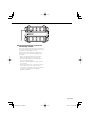
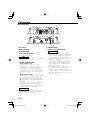
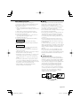
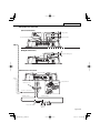
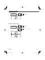
KAC-6203
STEREO/BRIDGEABLE POWER AMPLIFIER 7 page 2-13
INSTRUCTION MANUAL
AMPLIFICATEUR DE PUISSANCE STEREO/COMPATIBLE 7 page 14-25
MODE D’EMPLOI
STEREO-/ÜBERBRÜCKBARER LEISTUNGSVERSTÄRKER 7 Seite 26-37
BEDIENUNGSANLEITUNG
STEREO/OVERBRUGBARE VERMOGENSVERSTERKER 7 blz 38-49
GEBRUIKSAANWIJZING
AMPLIFICATORE DI POTENZA STEREO/COLLEGABILE 7 pagina 50-61
ISTRUZIONI PER L’USO
ESTÉRO/AMPLIFICADOR DE POTENCIA CONECTABLE 7 página 62-73
MANUAL DE INSTRUCCIONES
AMPLIFICADOR DE POTÊNCIA ESTÉREO/EM PONTE 7 página 74-85
MANUAL DE INSTRUÇÕES
© B64-3355-00/00 (EV)
B64-3355-00_00_E.indb 1
05.11.17 10:15:40 AM
Safety precautions
2 WARNING
To prevent injury or fire, take the following
precautions:
• When extending the ignition, battery, or ground
wires, make sure to use automotive-grade wires
or other wires with a 5 mm² (AWG 10) or more to
prevent wire deterioration and damage to the wire
coating.
• To prevent a short circuit, never put or leave any
metallic objects (such as coins or metal tools) inside
the unit.
• If the unit starts to emit smoke or strange smells,
turn off the power immediately and consult your
Kenwood dealer.
• Do not touch the unit during use because the
surface of the unit becomes hot and may cause
burns if touched.
2 CAUTION
To prevent damage to the machine, take the
following precautions:
• Be sure the unit is connected to a 12V DC power
supply with a negative ground connection.
• Do not open the top or bottom covers of the unit.
• Do not install the unit in a spot exposed to direct
sunlight or excessive heat or humidity. Also avoid
places with too much dust or the possibility of water
splashing.
• When replacing a fuse, only use a new one with the
prescribed rating. Using a fuse with the wrong rating
may cause your unit to malfunction.
• To prevent a short circuit when replacing a fuse, first
disconnect the wiring harness.
NOTE
• If you experience problems during installation,
consult your Kenwood dealer.
• If the unit does not seem to be working right,
consult your Kenwood dealer.
This product is not installed by the manufacturer of a
vehicle on the production line, nor by the professional
importer of a vehicle into an EU Member State.
Information on Disposal of Old Electrical
and Electronic Equipment (applicable for
EU countries that have adopted separate
waste collection systems)
Products with the symbol (crossed-out
wheeled bin) cannot be disposed as
household waste.
Old electrical and electronic equipment
should be recycled at a facility capable
of handling these items and their waste
byproducts. Contact your local authority
for details in locating a recycle facility
nearest to you. Proper recycling and waste
disposal will help conserve resources whilst
preventing detrimental effects on our
health and the environment.
Cleaning the unit
If the front panel gets dirty, turn off the power and
wipe the panel with a dry silicon cloth or soft cloth.
2 CAUTION
Do not wipe the panel with a hard cloth or a cloth
dampened by volatile solvents such as paint thinner
and alcohol. They can scratch the surface of the panel
and/or cause the indicator letters to peel off.
To prevent battery rise
When the unit is used in the ACC ON position without
turning the engine ON, it depletes the battery. Use it
after starting the engine.
Protection function
There is a Protection function installed in the unit to
protect the unit and speakers from various problems.
When Protection operates, the indicator informs you
of the condition. (Refer to page 5)
Accessories
Part name
External
View
Number of
Items
Self-tapping screws
(ø4 × 16 mm)
4
Terminal cover (Power
terminal)
1
Speaker level input
cable
1
2 English
B64-3355-00_00_E.indb 2
05.11.17 10:15:42 AM
Installation
Self-tapping screw
(ø4 × 16 mm)
330 mm
204 mm
230 mm
244 mm
254 mm
Ø4.6
Installation board, etc.
(thickness : 15 mm or more)
2 CAUTION
• Do not install in the below locations;
(Unstable location, In a location that interferes with driving, In a location that gets wet, In a dusty location, In a
place that gets hot, In a place that gets direct sunlight, In a location that gets hit by hot air)
• Do not install the unit under the carpet. Otherwise heat build-up occurs and the unit may be damaged.
• Install this unit in a location which allows heat to easily dissipate.
Once installed, do not place any object on top of the unit.
• The surface temperature of the amplifier will become hot during use. Install the amplifier in a place where
people, resins, and other substances that are sensitive to heat will not come into contact with it.
• When making a hole under a seat, inside the trunk, or somewhere else in the vehicle, check that there is nothing
hazardous on the opposite side such as a gasoline tank, brake pipe, or wiring harness, and be careful not to
cause scratches or other damage.
• Do not install near the dashboard, rear tray, or air bag safety parts.
• The installation to the vehicle should securely fasten the unit to a place in which it will not obstruct driving. If
the unit comes off due to a shock and hits a person or safety part, it may cause injury or an accident.
• After installing the unit, check to make sure that electrical equipment such as the brake lamps, turn signal lamps
and windshield wipers operate normally.
English
B64-3355-00_00_E.indb 3
3
05.11.17 10:15:42 AM
Controls / Indicator
2
1
40
30
20
10
(W)
2
1 FILTER switch
This switch allow filtering of the speaker output
signals.
• OFF position:
The original sound without filtering is output.
• LPF (Low-Pass Filter) position:
Only frequencies of 80 Hz or lower are output.
(Frequencies above 80 Hz are cut.)
The speaker output is automatically turned
monaural (L+R) and the bass boost function is
activated.
3 Power indicator
When the power is turned on, the Power indicator
lights.
If the Power indicator does not light when the
power is turned on, the protection function may
be activated. Check whether there is any indication
of trouble.
2 INPUT SENSITIVITY control
Set this control according to the pre-output level
of the center unit connected with this unit, or
to the maximum power output of the genuineaccessory car stereo.
Use the diagram on the right as a guide.
NOTE
For the pre-output level or the maximum power
output, refer to the <Specifications> in the
instruction manual of the center unit.
4 English
B64-3355-00_00_E.indb 4
05.11.17 10:15:43 AM
3
■ The protection function is activated in
the following situations:
This unit is equipped with a protection function for
protecting this unit and your speakers from various
accidents or problems that can occur.
When the protection function is triggered, the
Power indicator goes off and the amplifier stops
operating.
• When a speaker wire may be short-circuited.
• When a speaker output contacts ground.
• When the unit malfunctions and a DC signal is
sent to the speaker output.
• When the internal temperature is high and unit
won’t operate.
• When a ground wire of the center unit (cassette
receiver, CD receiver, etc.) or this unit is not
connected to a metal part serving as an electrical
ground passing electricity to the battery's
negative - terminal.
English
B64-3355-00_00_E.indb 5
5
05.11.17 10:15:44 AM
Connection
■ Terminal names
40
4
567
8
9
0
4 Fuse (40 A)
9 LINE IN terminal
5 Battery terminal
0 Speaker level input terminals
6 Ground terminal
7 Power control terminal
Controls the unit ON/OFF.
NOTE
Controls the unit power. Be sure to connect it with
all the systems.
8 Speaker output terminals
• Stereo Connections:
When you wish to use the unit as a stereo
amplifier, stereo connections are used.
The speakers to be connected should have an
impedance of 2Ω or greater. When multiple
speakers are to be connected, ensure that the
combined impedance is 2Ω or greater for each
channel.
• Bridged Connections:
NOTE
• The genuine-accessory car stereo shall have a
maximum power output of no more than 40 W.
• Do not connect the speaker output leads from
a power amplifier (Optional) to the speaker level
input terminals of this unit, for this may cause
malfunction or damage.
• Do not connect cables and leads to both RCA
cable input jacks and the speaker level input
terminals simultaneously, for this may cause
malfunction or damage.
• Connect the power control lead to a power
supply which can be turned ON/OFF by
the ignition key switch (ACC line). With this
connection, shock noise may be generated when
the power of the genuine-accessory car stereo is
switched ON/OFF.
When you wish to use the unit as a high-output
monaural amplifier, bridged connections are
used. (Make connections to the LEFT channel
9 and the RIGHT channel · SPEAKER OUTPUT
terminals.)
The speakers to be connected should have an
impedance of 4Ω or greater. When multiple
speakers are to be connected, ensure that the
combined impedance is 4Ω or greater.
2 CAUTION
The rated input of the speakers should be no
less than the maximum output of the amplifier.
Otherwise malfunction may result.
6 English
B64-3355-00_00_E.indb 6
05.11.17 10:15:45 AM
■ Installation procedure
■ Wiring
Since there are large variety of settings and
connections possible according to applications, read
the instruction manual well to select the proper
setting and connection.
1. Remove the ignition key and disconnect the
negative - terminal of the battery to prevent short
circuits.
2. Set the unit according to the intended usage.
3. Connect the input and output wires of the units.
4. Connect the speaker wires.
5. Connect the power wire, power control wire and
grounding wire following this order.
6. Install the unit in the car.
7. Connect the negative - terminal of the battery.
• Take the battery wire for this unit directly from the
battery. If it's connected to the vehicle’s wiring
harness, it can cause blown fuses etc.
• If a buzzing noise is heard from the speakers when
the engine is running, connect a line noise filter
(optional) to each of the battery wire.
• Do not allow the wire to directly contact the edge of
the iron plate by using Grommets.
• Connect the ground wire to a metal part of the car
chassis that acts as an electrical ground passing
electricity to the battery‘s negative - terminal.
Do not turn the power on if the ground wire is not
connected.
• Be sure to install a protective fuse in the power
cord near the battery. The protective fuse should
be the same capacity as the unit’s fuse capacity or
somewhat larger.
• For the power cord and ground, use a vehicle type
(fireproof ) power wring cord with a current capacity
greater than the unit’s fuse capacity. (Use a power
wiring cord with a diameter of 5 mm² (AWG 10) or
greater.)
• When more than one power amplifier are going
to be used, use a power supply wiring wire and
protective fuse of greater current-handling capacity
than the total maximum current drawn by each
amplifier.
2 WARNING
To prevent fire caused by a short in the wiring,
connect a fusible link or breaker nearby the battery’s
positive terminal.
2 CAUTION
• If sound is not output normally, immediately turn
power off and check connections.
• Be sure to turn the power off before changing the
setting of any switch.
• If the fuse blows, check wires for shorts, then replace
the fuse with one of the same rating.
• Check that no unconnected wires or connectors are
touching the car body. Do not remove caps from
unconnected wires or connectors to prevent short
circuits.
• Connect the speaker wires to appropriate speaker
connectors separately. Sharing the negative wire of
the speaker or grounding speaker wires to the metal
body of the car can cause this unit to fail.
• After installation, check that the brake lamps,
winkers, and wipers work properly.
■ Speaker selection
• The rated input power of the speakers that are
going to be connected should be greater than the
maximum output power (in Watts) of the amplifier.
Use of speakers having input power ratings that
are less than the output power of the amplifier will
cause smoke to be emitted as well as damage.
• The impedance of the speakers that are going
to be connected should be 2Ω or greater (for
stereo connections), or 4Ω or greater (for bridged
connections). When more than one set of speakers
are going to be used, calculate the combined
impedance of the speakers and then connect
suitable speakers to the amplifier.
4Ω
4Ω
4Ω
4Ω
8Ω
2Ω
Combined impedance
English
B64-3355-00_00_E.indb 7
7
05.11.17 10:15:46 AM
Connection
■ RCA cable or Speaker level input connection
(RCA cable Connections)
9
RCA cable*
CENTER UNIT
(CD receiver, etc.)
Power control wire
(Blue/ White)
Left input
Right input
Speaker level input cable
(Speaker level input Connections)
Cable Color of the connector
White
Left
White/Black
Gray
Right
Gray/Black
Genuine-accessory car
stereo
(No line output center unit
etc.)
0
Car fuse box
Battery
ACC
8 English
B64-3355-00_00_E.indb 8
05.11.17 10:15:47 AM
* Commercially available parts
■ Speaker wire connection
(Stereo Connections)
8
8
Lead terminal*
Left speaker
Right speaker
40
(Bridged Connections)
8
Speaker (Bridged)
40
■ Power wire connection
40
567
Lead terminal*
Terminal cover
Power control wire
Battery wire*
Ground wire*
Protective Fuse*
Battery
English
B64-3355-00_00_E.indb 9
9
05.11.17 10:15:47 AM
System examples
■ 2-channel system
CENTER UNIT
L
L
Left speaker
R
R
Right speaker
L
L
Left speaker
R
R
Right speaker
L
L
Subwoofer (L + R) (Bridged)
R
R
1
■ 2-channel + Subwoofer system
¡
CENTER UNIT
™
1
¡
™
1
10 English
B64-3355-00_00_E.indb 10
05.11.17 10:15:48 AM
■ Tri-mode
L
C
CENTER UNIT
L
L
R
R
(High pass)
Subwoofer
(L + R) (Bridged)
C
1
● Principle of Tri-mode
Method of frequency band division using a coil and capacitor…in case of 6dB/oct. slope
Coil (L): Passes low frequencies and blocks high frequencies.
(Low pass)
Capacitor (C): Passes high frequencies and blocks low
frequencies. (High pass)
Crossover Frequency
0 dB
-3 dB
L
159 x R
(mH)
fc
Frequency
159000
C=
(μF)
fc × R
C
L=
fc=Cut of Frequency (Hz)
R=Speaker Impedance (Ω)
● Example:
When it is required to set a crossover frequency of 120 Hz using speakers with an impedance of 4 ohms.
Prepare commercially-available coil and capacitor with the closest ratings to the results calculated from the
formula above. The capacitor rating should be as close as possible to 331.25 (μF) and the coil rating should be as
close as possible to 5.3 (mH).
2 CAUTION
• If you wish to bridge-connect a speaker, the speaker impedance must be no less than 4 ohms. Connecting a
speaker with an impedance lower than 4 ohms may damage the unit.
• Be sure to connect capacitors to speakers to which high frequencies will be passed. Failure to do so will result in
a drop of the combined impedance with the subwoofer.
• Ensure that the withstand voltage and current ratings of the capacitors (C) and coils (L) are sufficient.
English
B64-3355-00_00_E.indb 11
11
05.11.17 10:15:51 AM
Troubleshooting Guide
What might appear to be a malfunction in your unit may just be the result of slight misoperation or
miswiring. Before calling service, first check the following table for possible problems.
PROBLEM
POSSIBLE CAUSE
No sound.
• Input (or output) cables are
(No sound from one side.) disconnected.
(Blown fuse.)
• Protection circuit may be activated.
•
•
The output level is too
small (or too large).
The sound quality is bad.
(The sound is distorted.)
•
•
•
•
SOLUTION
• Connect the input (or output) cables.
• Check connections by referring to
<Protection function>.
Volume is too high.
• Replace the fuse and use lower
volume.
The speaker cord is shorted.
• After check the speaker cord and
fixing the cause of the short, replace
the fuse.
The input sensitivity adjusting control • Adjust the control correctly referring
is not set to the correct position.
to <Controls>.
The speakers wire are connected with • Connect them properly checking the
wrong 9 / · polarity.
9 / · of the terminals and wires
well.
A speaker wire is pinched by a screw • Connect the speaker wire again so
in the car body.
that it is not pinched by anything.
The switches may be set improperly. • Set switches properly by referring to
<System examples>.
12 English
B64-3355-00_00_E.indb 12
05.11.17 10:15:52 AM
Specifications
Specifications subject to change without notice.
Audio Section
Max Power Output ........................................................................................................................................................................ 600 W
Rated Power Output
Normal (4 Ω) (DIN : 45324 , +B = 14.4V) ......................................................................................................100 W × 2
Normal (2 Ω) (1 kHz, 1 % THD) ..........................................................................................................................150 W × 2
Bridged (4 Ω) (1 kHz, 1 % THD) .........................................................................................................................300 W × 1
Frequency Response (+0, –3 dB) ......................................................................................................................... 10 Hz – 50 kHz
Sensitivity (rated output) (MAX.) ...............................................................................................................................................0.2 V
Sensitivity (rated output) (MIN.) ................................................................................................................................................5.0 V
Signal to Noise Ratio ....................................................................................................................................................................100 dB
Input Impedance ............................................................................................................................................................................. 10 kΩ
Low Pass Filter Frequency (12 dB/oct.) .................................................................................................................................80 Hz
General
Operating Voltage ............................................................................................................................ 14.4 V (11 – 16 V allowable)
Current Consumption ..................................................................................................................................................................... 40 A
Dimensions (W × H × D) ...............................................................................................................................330 × 60 × 230 mm
Weight .................................................................................................................................................................................2.7 kg (6.0 lbs)
English
B64-3355-00_00_E.indb 13
13
05.11.17 10:15:52 AM


![KAC-5205 - [::] Kenwood ASC](http://vs1.manualzilla.com/store/data/006140129_1-15e69098803a5f51517e37a7883336ae-150x150.png)