1
KAC-746
4-CHANNEL POWER AMPLIFIER
INSTRUCTION MANUAL
© B64-1176-00 (EM)
Safety precautions
2WARNING
Take the following precautions to
prevent fire and avoid personal
injury :
• When extending the battery cable, or
ground cable, use 5mm2 (AWG10) or
larger automotive grade cable to avoid
cable deterioration or damage to the
covering.
• Check that no metal objects (coins, tools,
etc.) are left inside the unit to avoid short
circuits.
• If you smell or see smoke, turn the
power off immediately and consult your
Kenwood dealer.
• Do not touch the unit during use because
the surface of the unit becomes hot and
may cause burns if touched.
2CAUTION
Take the following precautions to
keep the unit in proper working
order.
• Do not open the top or bottom cover.
• Do not install the unit in places it is
exposed to direct sunlight, high heat or
humidity, water may splash over it, or
dust exists.
NOTE
• If you have difficulty in installing this unit
in your vehicle, contact your Kenwood
dealer.
Cleaning the unit
• If the surface is dirty, wipe it clean with a
silicon cloth or soft dry cloth with the
power off.
2CAUTION
Do not use hard cloths or paint thinner,
alcohol, or other volatile solvents. These
may damage external surfaces or remove
indicator characters.
• Be sure the unit is connected to a 12V
DC power supply with a negative ground
connection.
Accessories
Number
of Items
Part name
Battery cable
(Yellow) (6 m)
1
Round terminal
(Large)
1
Ground cable (Black)
(1 m)
1
Round terminal
(Medium)
2
Self-tapping screws
(ø4 × 16 mm)
4
Round terminal
(Small)
1
Terminal cover
(Power terminal)
1
Grommets
1
Part name
2
External
View
External
View
Number
of Items
Installation procedure
1. Remove the ignition key and disconnect the negative - terminal of the battery to prevent
short circuits.
2. Set the unit according to the intended usage.
3. Connect the input and output cables of the units.
4. Connect the speaker cables.
5. Connect the power cable, power control cable and grounding cable following this order.
6. Install the unit in the car.
7. Connect the negative - terminal of the battery.
2CAUTION
• Be sure to turn the power off before changing the setting of any switch.
• If the fuse blows, check cables for shorts, then replace the fuse with one of the same rating.
• Check that no unconnected cables or connectors are touching the car body. Do not remove
caps from unconnected cables or connectors to prevent short circuits.
• Connect the speaker cables to appropriate speaker connectors separately. Sharing the
negative cable of the speaker or grounding speaker cables to the metal body of the car can
cause this unit to fail.
• After installation, check that the brake lamps, winkers, and wipers work properly.
Installation
Self-tapping screw
(ø4 × 16 mm)
Installation board, etc.
(thickness : 15 mm or more)
• Since the power amplifier has no parts which require operation, it can be installed at a position
away from the driver’s seat without any hindrances.
As generally accepted positions for its installation, places such as inside the trunk, etc. can be
considered.
• Use the extension cables. (Optional.)
Length
0.5m
1m
2m
4m
5m
6m
Type
RCA cable
CA-2SL
CA-12SL CA-22SL
CA-52SL
RCA cable (ø7mm)
CA-3WL CA-13WL CA-23WL
CA-53WL
RCA cable (ø12mm)
CA-5W
CA-15W
CA-25W
CA-45W
CA-65W
2CAUTION
• Do not install the unit under the carpet. Otherwise heat build-up occurs and the unit may be
damaged.
• Install this unit in a location which allows heat to easily dissipate.
Once installed, do not place any object on top of the unit.
• After installing the unit, check to make sure that electrical equipment such as the brake lamps,
turn signal lamps and windshield wipers operate normally.
• Install the unit securely in a location that does not interfere with driving.
3
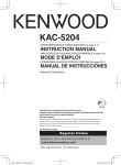
Controls
This is a 4 channel amplifier including 2 stereo amplifiers in a body. One amplifier is
referred to as amplifier A and the other is amplifier B. This unit is compatible with
a large variety of systems by combining the switches and functions described in
the following.
1
5
FUSE(30A)
SPEAKER LEVEL INPUT
LEFT
RIGHT
BRIDGED
POWER IN
SPEAKER OUTPUT
BRIDGED
A
GND
BATT
P.CON(REMOTE)
LEFT
RIGHT
A
SPEAKER LEVEL INPUT
A
A
B
L
R
B
B
234
6
B
L
R
7
8
9
0
!
@
100
80 150
100
80
GND
MONO
INPUT
SENSITIVITY(V)
0.5
FILTER
A + B
LINE OUT
L
0.3
INPUT
SENSITIVITY(V)
0.5
0.3
OPERATION
OPERATION
1.0
150
OFF
HPF
LPF
50 LPF 200
50 HPF 200
FREQUENCY(Hz)
A LINE IN B
L
MIN
STEREO
MONO(Lch)
L+R
CONTROL A
Amplifier A
1.0
R
MAX
A B
A
MIN
R
INPUT SELECTOR
# $ %^
FILTER
100
80
80 150 100
OFF
HPF
LPF
150
4 CHANNEL
POWER AMPLIFIER
50 LPF 200
50 HPF 200
MAX
STEREO
MONO(Lch)
L+R
FREQUENCY(Hz)
CONTROL B
Amplifier B
1 Fuse (30 A)
2 Battery terminal
3 Ground terminal
4 Power control (REMOTE) terminal
5 Amplifier A speaker output terminals
6 Amplifier B speaker output terminals
7 Speaker level input terminals
8 FREQUENCY control
When the FILTER switch is set to the HPF (High-Pass Filter) or LPF (Low-Pass Filter) position,
the threshold frequency can be adjusted with this control.
9 FILTER switch
High-pass or low-pass filtering can be applied to the speaker output according to the setting
of this switch.
0 OPERATION switch
The amplification methods of the signals input to amplifiers A and B can be selected
independently according to the setting of this switch.
4
• STEREO position:
The amplifier can be used as a stereo amplifier.
• L+R position:
The input left and right signals are combined before being amplified. Use this position when the
unit is used for subwoofer speakers or the L+R (monaural) sound is required.
• MONO (Lch) position:
Amplifies the signal input from the left side only. Set to this position and make bridged
connections to use as a high-power monaural amplifier. (The input right signal is not output.)
! INPUT SENSITIVITY control
Set this control according to the pre-output level of the center unit
connected with this unit, or to the maximum power output of the genuineaccessory car stereo.
Use the diagram on the right as a guide.
10
15
0.3
1.0
NOTE
For the pre-output level or the maximum power output, refer to the
“Specifications” in the instruction manual of the center unit.
0.5
25
MIN
MAX
(W)
@ RCA cable ground lead terminal
# INPUT SELECTOR switch
This switch selects the input method of the signals to be amplified by amplifiers A and B.
• A B position:
Amplifies both of the signals input to amplifiers A and B.
• A position:
Amplifies only signal input amplifier A with both amplifiers A and B.
$ Amplifier A LINE IN terminal
% Amplifier B LINE IN terminal
^ LINE OUT terminal
These jacks output respectively the signals input to amplifiers A and B. They always output
the stereo signals regardless of the position of the OPERATION switch.
Protection function
This unit is equipped with a protection function for protecting this unit and your
speakers from various accidents or problems that can occur.
When the protection function is triggered, the Power indicator goes off and the
amplifier stops operating.
■ Power indicator:
When the power is turned on, the Power indicator lights.
If the Power indicator does not light when the power is turned on, the
protection function may be activated. Check whether there is any
indication of trouble.
Power indicator
■ The protection function activates in the following
situations:
• When a speaker output contacts ground.
• When the unit malfunctions and a DC signal is sent to the speaker output.
• When the temperature of internal parts exceeds 120°C (248°F).
• When a ground cable of the center unit (cassette receiver, CD receiver,
etc.) or this unit is not connected to a metal part serving as an electrical
ground passing electricity to the battery's negative - terminal.
5
Connection
■RCA cable connection
BLINE IN (Rear)
2CAUTION
CENTER UNIT
(Cassette receiver,
CD receiver, etc.)
Power control cable
ALINE IN (Front)
RCA cable (Commercially
available part)
POWER IN
GND
BATT
Do not connect cables and
leads to both RCA cable input
jacks and the speaker input
terminals simultaneously, for
this may cause malfunction
or damage.
P.CON(REMOTE)
B Left input (White)
A Left input (White)
100
80
GND
MONO
INPUT
SENSITIVITY(V)
100
80 150
0.5
A
{B
LINE OUT
L
INPUT
SENSITIVITY(V)
0.5
0.3
OPERATION
FILTER
OPERATION
1.0
150
OFF
HPF
LPF
50 LPF 200
50 HPF 200
FREQUENCY(Hz)
A LINE IN B
L
0.3
1.0
MIN
R
MAX
STEREO
MONO(Lch)
L {R
A B
CONTROL A
MIN
R
A
FILTER
100
80
OFF
HPF
LPF
80 150 100
150
4 CHANNEL
POWER AMPLIFIER
50 LPF 200
50 HPF 200
MAX
FREQUENCY(Hz)
STEREO
MONO(Lch)
L {R
CONTROL B
INPUT SELECTOR
A Right input (Red) B Right input (Red)
RCA cable ground terminal
2CAUTION
When using an RCA cable with Do not use this terminal for power source
a ground lead attached, connect grounding. This unit will be damaged if the
the ground lead to this terminal. power source grounding wire is connected
to this terminal.
■Speaker level input connection
Connect the unit by inserting it in the connection between the genuine-accessory car stereo and
speakers.
Power control
(REMOTE) lead
terminal
ACC
+
Front
A Left input
(Front left)
-
A Right input
(Front right)
Battey
FUSE(30A)
POWER IN
GND
BATT
P.CON(REMOTE)
BRIDGED
SPEAKER OUTPUT
BRIDGED
A
RIGHT
SPEAKER LEVEL INPUT
LEFT
RIGHT
A
SPEAKER LEVEL INPUT
A
B
L
2CAUTION
LEFT
A
R
B
B Left input
(Rear left)
B
B
L
R
Genuine-accessory
car stereo
B Right input
(Rear right)
• The genuine-accessory car stereo shall have a
Rear
maximum power output of no more than 25 W.
• Do not connect the speaker output leads from a
power amplifier (Optional) to the speaker input terminals of this unit, for this may cause
malfunction or damage.
• Do not connect cables and leads to both RCA cable input jacks and the speaker input terminals
simultaneously, for this may cause malfunction or damage.
• Connect the power control lead to a power supply which can be turned ON/OFF by the ignition
key switch (ACC line).
With this connection, shock noise may be generated when the power of the genuine-accessory
car stereo is switched ON/OFF.
6
■Power and Speakers cable connection
• If a buzzing noise is heard from the
speakers when the engine is
running, connect a line noise filter
(optional) to each of the battery
cable.
• Do not allow the cord to directly
contact the edge of the iron plate
by using Grommets.
Front left
speaker
Front right
speaker
Power control
(REMOTE) lead
terminal
A Left output
(Front left)
FUSE(30A)
BRIDGED
POWER IN
LEFT
SPEAKER OUTPUT
BRIDGED
A
GND
BATT
A Right output
(Front right)
P.CON(REMOTE)
RIGHT
A
L
Battery
+
-
L
R
B Right output
(Rear right)
Rear right
speaker
Rear left
speaker
Battery cable (Yellow)
Round terminal
(Large)
B
B
B
R
Terminal cover
Fire wall
SPEAKER LEVEL INPUT
A
B
Grommets
SPEAKER LEVEL INPUT
LEFT
RIGHT
A
B Left output
(Rear left)
Power control cable
Ground cable
(Black)
Power terminal
Pass battery and ground cables through supplied
terminal cover and connect to respective
terminals. After completing connections, fasten
terminal cover over terminal bracket.
Round terminal (Medium)
Round terminal (Small)
2WARNING
To prevent fire caused by a short in the
wiring, connect a fusible link or breaker
nearby the battery’s positive terminal.
NOTE
Connect the ground cable to a metal part of
the car chassis that acts as an electrical
ground passing electricity to the battery‘s
negative - terminal. Do not turn the power
on if the ground cable is not connected.
(Bridged)
A Bridged
2CAUTION
If you wish to bridge-connect a
speaker, the speaker impedance must
be no less than 4 ohms.
Connecting a speaker with an
impedance lower than 4 ohms may
damage the unit.
examples:
FUSE(30A)
L
L
R
R
≥4Ω
≥8Ω ≥8Ω
POWER IN
GND
BATT
P.CON(REMOTE)
BRIDGED
SPEAKER OUTPUT
BRIDGED
A
LEFT
RIGHT
SPEAKER LEVEL INPUT
LEFT
RIGHT
A
SPEAKER LEVEL INPUT
A
A
B
L
R
B
B
B
L
R
B Bridged
7
System examples
■ Full-range 4-channel + Subwoofer system
L
CENTER UNIT
R
L
R
L
R
A
B
Switch setting
100
80
L
100
80 150
OPERATION
FILTER
150
OFF
HPF
LPF
R
50 LPF 200
50 HPF 200
FREQUENCY(Hz)
L
STEREO
MONO(Lch)
L+R
CONTROL A
R
A B
A
OPERATION
INPUT SELECTOR
100
80
FILTER
80 150 100
OFF
HPF
LPF
A+B
LINE OUT
150
50 LPF 200
50 HPF 200
FREQUENCY(Hz)
MONO(Lch)
STEREO
L+R
CONTROL B
Amplifier
■ High-power 2-channel system
L
CENTER UNIT
R
L
R
L
R
A
B
L
Switch setting
(Bridged)
100
80
L
100
80 150
OPERATION
FILTER
150
OFF
HPF
LPF
R
50 LPF 200
50 HPF 200
FREQUENCY(Hz)
(Bridged)
R
STEREO
MONO(Lch)
L+R
CONTROL A
A B
A
OPERATION
INPUT SELECTOR
100
80
FILTER
80 150 100
OFF
HPF
LPF
A+B
LINE OUT
150
50 LPF 200
50 HPF 200
FREQUENCY(Hz)
MONO(Lch)
STEREO
L+R
CONTROL B
■ High-pass (80 Hz) + Subwoofer(80 Hz) system
CENTER UNIT
L
R
L
R
L
R
A
B
L
R
L
R
A+B
LINE OUT
Switch setting
100
80
(High pass)
100
80 150
OPERATION
FILTER
150
OFF
HPF
LPF
50 LPF 200
50 HPF 200
FREQUENCY(Hz)
Subwoofer
(L + R)
(Bridged)
STEREO
MONO(Lch)
L+R
CONTROL A
A B
A
OPERATION
INPUT SELECTOR
100
80
FILTER
80 150 100
OFF
HPF
LPF
150
50 LPF 200
50 HPF 200
FREQUENCY(Hz)
MONO(Lch)
STEREO
L+R
CONTROL B
■ Tri-mode
Switch setting
C
L
CENTER UNIT
R
L
R
A
B
L
R
L
R
L
100
80
L
OPERATION
FILTER
150
OFF
HPF
LPF
50 LPF 200
50 HPF 200
C
C
FREQUENCY(Hz)
STEREO
MONO(Lch)
L+R
CONTROL A
L
A B
A
INPUT SELECTOR
R
100
80 150
OPERATION
FILTER
OFF
HPF
LPF
A+B
LINE OUT
C
100
80
80 150 100
150
50 LPF 200
50 HPF 200
MONO(Lch)
STEREO
L+R
FREQUENCY(Hz)
CONTROL B
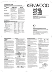
●Principle of Tri-mode
Method of frequency band division using a coil and capacitor•••in case of 6dB/oct. slope
Coil (L): Passes low frequencies and blocks high
Crossover Frequency
frequencies. (Low pass)
0 dB
Capacitor (C): Passes high frequencies and blocks low
-3 dB
frequencies. (High pass)
159000
L
C
C=
(µF)
fc=Cut of Frequency (Hz)
fc x R
R=Speaker Impedance (Ω)
159
x
R
Frequency L=
(mH)
fc
●Example:
When it is required to set a crossover frequency of 120 Hz using speakers with an
impedance of 4 ohms.
Prepare commercially-available coil and capacitor with the closest ratings to the results
calculated from the formula above. The capacitor rating should be as close as possible to
331.25 (µF) and the coil rating should be as close as possible to 5.3 (mH).
2CAUTION
If you wish to bridge-connect a speaker, the speaker impedance must be no less than 4 ohms.
Connecting a speaker with an impedance lower than 4 ohms may damage the unit.
8
Troubleshooting guide
Often, what appears to be a malfunction is due to user error. Before
calling for service, please consult the following table.
Symptom
Cause
Remedy
No sound.
(No sound from one side.)
• Input (or output) cables are
disconnected.
• Protection circuit may be
activated.
• The fuse may be blown
because the volume was too
high.
• Connect the input (or output)
cables.
• Check connections by referring
to "Protection function".
• Replace the fuse with a new
fuse and use a lower volume.
The output level is too
small (or too large).
The input sensitivity adjusting
control is not set to the correct
position.
Adjust the control correctly
referring to “Controls”.
The sound quality is bad.
(The sound is distorted.)
• The speakers cable are
connected with wrong + / polarity.
• A speaker cable is pinched by a
screw in the car body.
• Connect them properly checking
the + / - of the terminals and
cables well.
• Connect the speaker cable again
so that it is not pinched by
anything.
• Set switches properly by
referring to "Controls" and
"System examples".
• The switches may be set
improperly.
Specifications
Specifications subject to change without notice.
Audio Section
Max Power Output (4 Ω)
4 Channel Mode ..........................................................................................................70 W × 4
3 Channel Mode ....................................................................................70 W × 2 + 200 W × 1
2 Channel Mode ........................................................................................................200 W × 2
Rated Power Output (4 Ω)
4 Channel Mode ..................................................................35 W × 4 (DIN45324, +B=14.4 V)
3 Channel Mode) ..................35 W × 2 (1 kHz, 0.08 % THD) + 100 W × 1 (1 kHz, 0.8 % THD
2 Channel Mode........................................................................100 W × 2 (1 kHz, 0.8 % THD)
Rated Power Output (2 Ω)
4 Channel Mode..........................................................................50 W × 4 (1 kHz, 0.8 % THD)
Frequency Response (+0, –1 dB) ............................................................................5 Hz ~ 50 kHz
Signal to Noise Ratio............................................................................................................100 dB
Sensitivity (MAX) (rated output) ............................................................................................0.15 V
Sensitivity (MIN) (rated output) ..............................................................................................4.0 V
Input Impedance....................................................................................................................10 kΩ
Low Pass Filter (12 dB/oct.) (Variable) ........................................................................50 ~ 200 Hz
High Pass Filter (12 dB/oct.) (Variable) ........................................................................50 ~ 200 Hz
General
Operating Voltage ..............................................................................14.4 V (11 ~ 16 V allowable)
Current Consumption (1 kHz, 10% THD) ................................................................................28 A
Dimensions (W × H × D) ................................................................................290 × 52 × 230 mm
Weight ..................................................................................................................................3.1 kg
9