1
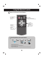
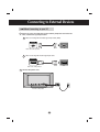
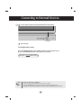
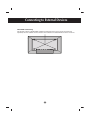
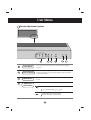
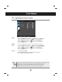
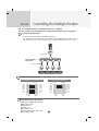
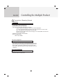
User’s Guide
M2900S
M3800S
Make sure to read the Safety Precautions before using the product.
Keep the User's Guide(CD) in an accessible place for future reference.
See the label attached on the product and give the information to your dealer when you ask
for service.
Using the Remote Control
Name of the Remote Control Buttons
• Power On/Off Button
• Source Button
Select input source
(RGB, DVI)
SOURCE
• Auto Button
Automatic adjustment function
(Operational for the analog signal only)
MENU
•
buttons
OSD Menu Navigation
buttons
•
Select OSD Menu Item.
: Decrement Value
: Increment Value
• Menu Button
OSD On/ Off
Sub OSD Menu out
ZOOM
•
button
Zoom Hot key
(Normal Zoom Full)
* Only OSD menu off
Inserting batteries into remote control.
CR2025
1. Slide off the battery cover.
2. Insert the batteries with correct polarity (+/-).
3. Close the battery cover.
• Dispose of used batteries in the recycle bin to prevent environmental pollution.
1
Name and Function of the Parts
* The product image in the user’s guide could be different from the actual image.
Rear View
DVI IN
RGB IN
RS-32C IN
DVI, RGB Ports
RS-232C Serial Port
Wired Remote Control Port
Power Connector : Connect the power cord
2
REMOTE
CONTROL IN
AC-IN
Connecting to External Devices
When Connecting to your PC
First of all, see if the computer, product and the peripherals are turned off.
Then, connect the signal input cable.
A When connecting with the D-Sub signal input cable. (RGB)
RGB IN
PC
Rear side of the product.
B When connecting with the DVI signal input cable.
DVI IN
PC
Rear side of the product.
Connect the power cord.
Rear side of the product.
3
Connecting to External Devices
1 Turn on power by pressing the power button on the product.
SOURCE
ON/OFF
Zoom
Power button
2 Turn on the PC.
To change input source
Press the SOURCE button on the remote control to select the input signal.
Or, press the SOURCE button on the bottom of the product.
DVI signal
Note
D-Sub signal
• How to connect to two computers.
Connect the signal cables (DVI and D-Sub) to each computer.
Press the SOURCE button on the remote control to select the computer to use.
• Directly connect to a grounded power outlet or power strip (three prong connector.)
4
Connecting to External Devices
VESA FDMI wall Mounting
This product supports a VESA FDMI compliant mounting interface. These mounts are purchaed
separately and not available from LG. Refer to the instructions included with hte mount for more info.
5
User Menus
Screen Adjustment options
SOURCE
ON/OFF
Zoom
Power Button
• Press this button to turn on the power. Press this button again to
turn it off.
Power Indicator
• This Indicator lights up green when the display operates normally(on
mode). If the display is in sleep (Energy Saving) mode, this indicator
color changes to amber.
MENU Button
• Use this button to show/hide the OSD (On Screen Display) menu
screen.
OSD Select /
Adjust Button
• Use this button to select an icon or adjust the setting in the OSD screen.
OSD Menu Navigation up and down
: Zoom Hot key (Normal
Zoom
Full)
Zoom
: Select Menu Item, Decrement Value
: Select Menu Item, Increment Value
6
User Menus
Screen Adjustment options
SOURCE Button
To change input source depending on connected signal.
Press the SOURCE button on the remote control to select the
input signal.
Or, press the SOURCE button on the bottom of the product.
IR Receiver
DVI signal
D-Sub signal
Digital signal
15-pin D-Sub analog signal
• This is where the unit receives signals from the remote control.
7
User Menus
OSD Menu
Icon
Function Description
Adjusts screen brightness, contrast and color that you prefer.
PICTURE
Adjusts the screen size.
ZOOM
Adjusts the timer options.
TIMER
Adjusts the OSD image.
OSD
Note
OSD(On Screen Display)
The OSD function enables you to adjust the screen status conveniently since it provides
graphical presentation.
8
User Menus
How to adjust the OSD (On Screen Display) screen
MENU
Pops up
the menu
screen
MENU
Move where
you want to
adjust
Select a
menu icon
Move where
you want to
adjust
Select a
menu icon
Adjust the status
Save
adjustment
MENU
Exit from the
menu screen.
• Use the remote control to adjust the OSD screen.
1
Press the MENU Button, then the main menu of the OSD appears.
2
To access a control, use the
3
When the icon you want becomes highlighted, press the
4
Use the
5
Accept the changes by pressing the MENU Button.
6
Exit the OSD by pressing the MENU Button.
Buttons.
Button.
Buttons to adjust the item to the desired level.
How to adjust the screen automatically
Press the AUTO button on a remote Control in the PC analog signal.
Then optimal screen settings will be selected that fit into the current
mode. If adjustment is not satisfactory, you can adjust the screen
manually.
9
Auto-Adjust
User Menus
Adjusting Screen Color
PICTURE
Contrast
Brightness
Color Temp.
Cool
H- Position
V-Position
Clock
Phase
Auto Adjust
Move
Select
MENU
Exit
Contrast
Brightness
Adjust the difference between the light and dark levels in the picture.
To adjust the brightness of the screen.
Color Temp
Color Settings
PICTURE
Contrast
Brightness
Color Temp.
Cool
H- Position
V-Position
Clock
Phase
Auto Adjust
Move
Select
MENU
Exit
• Cool : Slightly purplish white.
• Normal : Slightly bluish white.
• Warm : Slightly reddish white.
• User : Select this option to use the user-defined settings.
10
User Menus
Adjusting Screen Color
PICTURE
Color Temp.
Cool
User - R
User - G
User - B
Move
Select
MENU
Exit
Red / Green / Blue
Set your own color levels.
H-Position : Moving the screen position horizontally.
V-Position : Moving the screen position vertically.
Clock : To minimize any vertical bars or stripes visible on the screen background. The
horizontal screen size will also change. This function is available for analog signals only.
Phase : To adjust the focus of the display. This item allows you to remove any horizontal
noise and clear or sharpen the image of characters. This function is available for analog
signals only.
Auto Adjust (RGB PC input only) : This button is for the automatic adjustment of the
screen position, clock and phase. This function is available for analog signals only.
11
User Menus
Adjusting Screen size
Resolution
ZOOM
Resolution
1366X768
Mode
Zoom
0
Zoom Fine
Move
1.
For more improved or better
picture quality, select the same
mode corresponding to computer
resolution.
Select
MENU
Exit
ZOOM
Press the
Resolution
button.
1366X768
Setup Mode
Move
2.
Select
MENU
Exit
ZOOM
Press the
Resolution
1366X768
Setup Mode
Move
3.
Select
MENU
Exit
Accept the changes by pressing the
12
Button.
button.
User Menus
Adjusting Screen size
Mode
Zoom Fine
To select the image size of the screen.
Normal
The aspect ratio is not adjusted from the original. It is set by the
program being watched.
Full
When your AV receives the wide screen signal, it will lead you to
adjust the picture horizontally or vertically, in a linear proportion,
to fill the entire screen fully.
Zoom
When an image created based on M2900S model resolution (1366 X 480)
and an image based on M3800S model resolution (1366 X 398) are used in
different models, this function adjusts an image to fit to the screen size
without cutting it or leaving any empty space on screen.
To adjust the enlarged or reduced areas on the screen when the product is in Zoom mode.
13
User Menus
Adjusting the timer function
TIMER
Clock
02:02
On Time
06:30
Off Time
22:00
Function
OFF
Move
Select
MENU
Exit
Clock
If the current time is incorrect, reset the clock manually.
1) Press the MENU button and then use
button to select the TIMER menu.
2) Press the
button and then use
button to select the Clock menu.
3) Press the
button and then use
button to set the hour(00~23).
4) Press the
button and then use
button to set the minutes(00~59).
5) Press the MENU button.
On/ Off
Time
The off time automatically switches the set to standby at the pre-set time.
button to select the TIMER menu.
1) Press the MENU button and then use
2) Press the
button and then use
button to select Off Time or On Time.
3) Press the
button and then use
button to set the hour(00~23).
4) Press the
button and then use
button to set the minutes(00~59).
5) Press the MENU button.
Function
To set automatic On/Off.
On : Automatically turn the product On/Off at preset times.
Off : Disable the On/Off Time function.
Note
In the event of power interruption (disconnection or power failure), the clock must be reset.
Once the on or off time is set, these functions operate daily at the preset time.
Off time function overrides On time function if they are set to the same time.
When On time is operated, input screen is turned on as it was turned off.
14
User Menus
Adjusting OSD image
OSD
OSD
Set ID
1
H-Position
3
V-Position
10
On-Screen Time
10
Halftone
63
Factory Reset
Move
Select
MENU
Exit
Set ID
You can assign a unique Set ID NO (name assignment) to each
product when several products are connected for display. Specify the
button and exit. Use the assigned Set
number (1~99) using the
ID to individually control each product using the Product Control
Program.
H-Position
Moving the OSD screen position horizontally.
V-Position
Moving the OSD screen position vertically.
On-Screen Time
To set the period of time that the OSD is displayed on the screen.
(Available times : 3 to 24 second.)
Halftone
To adjust the transparency of the OSD menu screen.
Factory Reset
Select this option to return to the default factory settings.
15
Troubleshooting
No image is displayed
● Is the product power cord connected?
• See if the power cord is properly connected to the
outlet.
● Is the power indicator light on?
• See if the power switch is turned on.
• May need service.
● Power is on, power indicator is green
but the screen appears extremely dark.
• Adjust brightness and contrast again.
• Backlight may need repair.
● the power indicator amber?
● Does the 'Out of range' message
appear?
● Does the 'no signal' message appear?
• If the product is in power saving mode, move the
mouse or press any key.
• Turn both devices off and then back on.
• The signal from the PC (video card) is out of the
vertical or horizontal frequency range of the
product. Adjust the frequency range by referring
to the Specifications in this manual.
* Maximum resolution
RGB : 1280 x 1024 @60Hz
DVI : 1280 x 1024 @60Hz
• The signal cable between PC and product is not
connected. Check the signal cable.
• Press the 'SOURCE' menu in the remote Control
to check the input signal.
'Unknown Product' message appears when the product is connected.
● Did you install the driver?
• Install the product driver, which is provided with
the product, or download it from the web site.
(http://www.lge.com)
• See if the plug&play function is supported by
referring to the video card user manual.
Note
* Vertical frequency: To enable the user to watch the product display, screen image should be changed tens of times
every second like a fluorescent lamp. The vertical frequency or refresh rate is the times of image display per second.
The unit is Hz.
* Horizontal frequency: The horizontal interval is the time to display one vertical line. When 1 is divided by the
horizontal interval, the number of horizontal lines displayed every second can be tabulated as the horizontal
frequency. The unit is kHz.
16
Troubleshooting
The screen image looks abnormal.
● Is the screen position wrong?
• D-Sub analog signal – Press the “AUTO” button in
the remote control to automatically select the
optimal screen status that fits into the current
mode. If adjustment is not satisfactory, use the
Position OSD menu.
• See if the video card resolution and frequency are
supported by the product. If the frequency is out of
range, set to the recommended resolution in the
Control Panel – Display – Setting menu.
● Do thin lines appear on the
background screen?
• D-Sub analog signal – Press the “AUTO” button
in the remote control to automatically select an
optimal screen status that fits into the current
mode. If adjustment is not satisfactory, use the
Clock OSD menu.
● Horizontal noise appears or the
characters look blurred.
• D-Sub analog signal – Press the “AUTO” button
in the remote control to automatically select an
optimal screen status that fits into the current
mode. If adjustment is not satisfactory, use the
Phase OSD menu.
● The screen is displayed abnormally.
• The proper input signal is not connected to the
signal port. Connect the signal cable that matches
with the source input signal.
After-image appears on the product.
● After-image appears when the
product is turned off.
• If you use a fixed image for a long time, the pixels
may be damaged quickly. Use the screen-saver
function.
17
Troubleshooting
Screen color is abnormal.
● Screen has poor color resolution
(16 colors).
• Set the number of colors to more than 24 bits (true
color)
Select Control Panel – Display – Settings – Color
Table menu in Windows.
● Screen color is unstable or monocolored.
• Check the connection status of the signal cable.
Or, re-insert the PC video card.
● Do black spots appear on the screen?
• Several pixels (red, green, white or black color)
may appear on the screen, which can be
attributable to the unique characteristics of the
LCD panel. It is not a malfunction of the LCD.
18
Specifications
The product specifications can change without prior notice for product improvement.
M2900S
LCD Panel
Power
29.1 inches (73.95 cm) TFT (Thin Film Transistor)
LCD (Liquid Crystal Display) Panel
Visible diagonal size: 73.95 cm
0.17025 mm X RGB X 0.51075 mm (Pixel Pitch)
Rated Voltage
Power Consumption
AC 100-240V~ 50/60Hz 1.1A
On Mode
: 65W Typ.
Sleep Mode
: ≤ 2W
Off Mode
: ≤ 1W
Dimensions
&Weight
H
W
D
Width x Height x Depth
76.58 cm (30.15 inches) x 30.82 cm (12.13 inches) x 9.8 cm (3.86 inches)
Net
13 kg (28.66 lbs)
NOTE
Information in this document is subject to change without notice.
19
Specifications
The product specifications can change without prior notice for product improvement.
M3800S
LCD Panel
Power
38.1 inches (96.89 cm) TFT (Thin Film Transistor)
LCD (Liquid Crystal Display) Panel
Visible diagonal size: 96.89 cm
0.227 mm X RGB X 0.681 mm (Pixel Pitch)
Rated Voltage
Power Consumption
AC 100-240V~ 50/60Hz 1.3A
On Mode
: 88W Typ.
Sleep Mode
: ≤ 2W
Off Mode
: ≤ 1W
Dimensions
&Weight
H
W
D
Width x Height x Depth
98.88 cm (38.93 inches) x 32.92 cm (12.96 inches) x 9.2 cm (3.62 inches)
Net
16 kg (35.27 lbs)
NOTE
Information in this document is subject to change without notice.
20
Specifications
The product specifications can change without prior notice for product improvement.
Video Signal
Max. Resolution
RGB : 1366 X 768 @60Hz (1280 X 1024@60Hz)
DVI : 1366 X 768 @60Hz (1280 X 1024@60Hz) – It may not
be supported depending on the OS or video card type.
Recommended Resolution RGB : 1360 X 768 @60Hz
DVI : 1360 X 768 @60Hz – It may not be
supported depending on the OS or video card type.
Horizontal Frequency
RGB : 28 - 70 kHz
DVI : 28 - 70 kHz
Vertical Frequency
57 - 63 Hz
Synchronization Type Separate/Digital
Input Connector
Environmental
Conditions
15-pin D-Sub type, DVI (digital), RS-232C
Operational Condition Temperature: 5˚C ~ 35˚C , Humidity: 10% ~ 80%
Storage Condition
Temperature: -20˚C ~ 60˚C , Humidity: 5% ~ 90%
NOTE
Information in this document is subject to change without notice.
21
Specifications
PC Mode – Preset Mode
1
2
3
4
5
6
7
8
Preset mode
Horizontal
Frequency
(kHz)
Vertical
Frequency
(Hz)
640 x 480
720 x 400
720 x 400
800 x 600
800 x 600
1024 x 768
1024 x 768
1360 x 768
31.469
31.468
31.5
37.354
37.879
47.816
48.363
47.72
59.94
70.08
70.156
59.861
60.317
59.92
60.004
59.799
Preset mode
9
10
11
12
13
14
1360 x 768
1360 x 768
1366 x 768
1366 x 768
1280 x 1024
1280 x 1024
Horizontal Vertical
Frequency Frequency
(Hz)
(kHz)
47.72
47.712
47.713
49.02
63.668
63.981
59.799
60.015
59.65
60.0
59.895
60.02
* 8~14 Select Resolution In OSD Zoom Menu
Power Indicator
Mode
On Mode
Sleep Mode
Off Mode
Product
Green
Amber
Red
22
RS-232C
Controlling the Multiple Product
Use this method to connect several products to a single PC.
You can control several products at a time by connecting them to a single PC.
Connecting the cable
Connect the RS-232C cable as shown in the picture.
* The RS-232C protocol is used for communication between the PC and product. You can
turn the product on/off, select an input source or adjust the OSD menu from your PC.
PC
RS-232C Cable
< RS-232C Distributor(Not included) >
RS-232C Cable
RS-232C IN
monitor 1
RS-232C IN
RS-232C IN
RS-232C IN
monitor 2
monitor 3
monitor 4
RS-232C Configurations
3-Wire Configurations (Not Standard)
7-Wire Configurations (Standard RS-232C cable)
PC
RXD
TXD
GND
DTR
DSR
RTS
CTS
2
3
5
4
6
7
8
D-Sub 9
(Female)
PC
Monitor
2
3
5
4
6
7
8
RXD
TXD
GND
DTR
DSR
RTS
CTS
TXD
RXD
GND
DSR
DTR
CTS
RTS
D-Sub 9
(Female)
D-Sub 9
(Male)
Communication Parameter
▲▲ ▲ ▲ ▲▲▲
Baud Rate : 9600buadRate (UART)
Data Length : 8bits
Parity Bit : None
Stop Bit : 1bit
Flow Control : None
Communication Code : ASCII code
Use a straight cable
2
3
5
4
6
7
8
A1
Monitor
2
3
5
4
6
7
8
D-Sub 9
(Male)
TXD
RXD
GND
DSR
DTR
CTS
RTS
RS-232C
Controlling the Multiple Product
Command Reference List
01. Power
02. Source
03. Brightness
04. Contrast
05. Color Temperature
06. Resolution
07. Zoom
08. Auto Adjust
COMMAND1
j
j
j
j
j
j
j
j
A2
COMMAND2
k
l
m
n
p
q
r
s
DATA(ASCII)
000 - 001
000 - 001
000 - 100
000 - 100
000 - 003
000 - 002
000 - 002
000
RS-232C
Controlling the Multiple Product
Transmission / Receiving Protocol
Transmission
[Command1][Set ID][Command2][Data][Cr]
* [Command 1]: First command. (j)
* [Command 2]: Second command.
* [Set ID]: Set up the Set ID number of product.
range : 00~99. by setting '0', server can control all products.
* In case of operating with more than 2 sets using set ID as '0' at the same
time, it should not be checked the ack message.
Because all sets will send the ack message, so it's impossible the check the
whole ack messages.
* [DATA]: To transmit command data.
* [Cr]: Carriage Return
ASCII code ‘0x0D’
OK Acknowledgement
[OK]
* The Product transmits ACK (acknowledgement) based on
this format when receiving normal data. At this time, if the
data is data read mode, it indicates present status data.
If the data is data write mode, it returns the data of the PC
computer.
Error Acknowledgement
[NG]
* If there is error, it returns NG.
A3
RS-232C
Controlling the Multiple Product
Transmission / Receiving Protocol
▲
01. Power(Command : k)
To control Power On/Off of the Set.
Transmission
[j][Set ID][k][Data][Cr]
Data(ASCII) 000 : Power Off
001 : Power On
Acknowledgement
[OK]
▲
02. Source (Command : l)
To select input source for the Set.
You can also select an input source using the SOURCE
button on the remote control.
Transmission
[j][Set ID][l][Data][Cr]
Data(ASCII) 000 : RGB
001 : DVI
Acknowledgement
[OK]
A4
Controlling the Multiple Product
RS-232C
Transmission / Receiving Protocol
▲
03. Brightness(Command : m)
To adjust screen brightness.
You can also adjust the brightness in the Picture menu.
Transmission
[j][Set ID][m][Data][Cr]
Data(ASCII)
Min : 000 ~ Max : 100
Acknowledgement
[OK]
▲
04. Contrast(Command : n)
To adjust screen contrast.
You can also adjust the contrast in the Picture menu.
Transmission
[j][Set ID][n][Data][Cr]
Data(ASCII)
Min : 000 ~ Max : 100
Acknowledgement
[OK]
A5
RS-232C
Controlling the Multiple Product
Transmission / Receiving Protocol
▲
05. Color Temperature (Command : p)
To adjust the screen color temperature.
Transmission
[j][Set ID][p][Data][Cr]
Data (ASCII)
000 : Normal
001 : Cool
002 : Warm
003 : User
Acknowledgement
[OK]
▲
06. Resolution (Command : q)
To adjust the screen format.
Transmission
[j][Set ID][q][Data][Cr]
Data (ASCII)
000 : 1366 X 768
001 : 1360 X 768
002 : 1024 X 768
Acknowledgement
[OK]
A6
Controlling the Multiple Product
RS-232C
Transmission / Receiving Protocol
▲
07. Zoom (Command : r)
To adjust the enlarged or reduced areas on the screen when the product is in Zoom mode.
Transmission
[j][Set ID][r][Data][Cr]
Data (ASCII)
000 : Normal
001 : Zoom
002 : Full
Acknowledgement
[OK]
▲
08. Auto adjust (Command: s)
To adjust picture position and minimize image shaking
automatically. it works only in RGB mode.
Transmission
[j][Set ID][s][Data][Cr]
Data (ASCII)
000 : To set
Acknowledgement
[OK]
A11
IR Codes
Remote Control
▲
How to connect
Connect your wired remote control to Remote Control port on the Product.
▲
Output waveform
Remote Control IR Code
single pulse, modulated with 37.917KHz signal at 455KHz
Tc
Carrier frequency
FCAR = 1/Tc = fosc/12
Duty ratio = T1/Tc = 1/3
T1
▲
Configuration of frame
• 1st frame
Lead
code
Low
custom code
High
custom code
Data code
Data code
C0 C1 C2 C3 C4 C5 C6 C7 C0 C1 C2 C3 C4 C5 C6 C7 D0 D1 D2 D3 D4 D5 D6 D7 D0 D1 D2 D3 D4 D5 D6 D7
▲
Lead code
9ms
4.5ms
▲
Bit description
• Bit "0"
• Bit "1"
0.56ms
0.56ms
1.12ms
2.24ms
▲
Frame interval : Tf
• The waveform is transmitted as long as a key is depressed.
Tf
Tf
Tf=108ms@455KHz
A8
IR Codes
Remote Control
Function
Note
▲
R/C Button (Menu Navigation, Zoom Hot key)
▼
R/C Button (Menu Navigation)
R/C Button (Increment Value, Select menu item)
▲
0FH
16H
17H
12H
03H
07H
11H
0CH
▲
Code(Hexa)
R/C Button (Decrement Value, Select menu item)
POWER ON/OFF
PR/C Button (Power On/Off)
SOURCE
MENU
AUTO ADJUST
R/C Button (D-Sub, DVI)
R/C Button (Menu On/Off)
Discrete IR Code (D-Sub Only)
A9