1
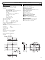
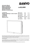
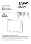
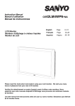
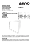
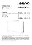
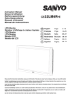
Instruction Manual
Manuel d'utilisation
Bedienungsanleitung
Gebruiksaanwijzing
Manuale d'Istruzioni
CE42SR1
Manual de instrucciones
LCD Monitor
Moniteur d'affichage à cristaux liquides
LCD-Monitor
LCD-Monitor
Monitor LCD
Monitor de LCD
GB English
Page
2~12
F
Français
Page
13~22
D
Deutsch
Seite
23~32
NL Nederlands Bladzijde 33~42
I
Italiano
Pagine
43~52
E
Español
Página
53~68
Please read this Instruction book before using your LCD monitor. We wish you many hours of pleasure from your new LCD monitor
Veuillez lire attentivement ce mode d’emploi avant d’utiliser votre moniteur d’affichage à cristaux liquides. Nous espérons que votre
nouveau dispositif d'affichage vous procurera de nombreux instants de bonheur.
Lesen Sie diese Anleitung bitte aufmerksam durch, bevor Sie Ihren LCD- Monitor in Betrieb nehmen. Wir wünschen Ihnen viel Freude
mit Ihrem neuen Gerät.
Lees deze handleiding voordat u uw LCD- monitor gaat gebruiken. We wensen u vele uren van plezier met uw nieuwe beeldscherm.
Leggere attentamente questo manuale d’istruzioni prima di utilizzare il monitor LCD. Vi ringraziamo per aver scelto un monitor LCD
Sanyo che vi consentirà di trascorrere momenti piacevoli e divertenti.
Lea este manual de instrucciones antes de usar su nuevo monitor. Deseamos que disfrute de él muchas horas.
SAFETY PRECAUTIONS
GB
GB
CAUTION: Please read and retain for your safety. This unit has been engineered and manufactured to assure your personal safety, but
improper use can result in potential electric shock or fire hazards. In order not to defeat the safeguards incorporated in this monitor observe the
following basic rules for its installation, use and servicing.
The operating temperature range of this monitor is guaranteed
0°c ~ 40°c/ 32°F ~104°F. It is not recommended to install the screen
Installation and Use
Do not allow anything to rest on the power
cord. Do not locate this LCD monitor where
the cord will be damaged by people walking
on it.
Do not overload wall outlets and extension
cords as this can result in fire or electric
shock.
A suitable socket outlet must be provided
near to the monitor and shall be easily accessible.
Do not place this LCD monitor near any heat sources such as
radiators, heaters, stoves and other heat-generating products
(including amplifiers).
Do not place your LCD monitor on an unstable stand, shelf or
table. Serious injury to an individual, and damage to the LCD
monitor may result if it should fall. Your sales person can
recommend approved wall mounting kit. A special wall mounting
kit is available for this model.
This LCD monitor should be operated only from the type of power
source indicated on the monitor or as indicated in the Operating
Instructions. If you are not sure of the type of power supply,
consult your sales person or your local power company.
For added protection it is strongly recommended that this LCD
monitor is supplied via an approved earth fault protection device.
WARNING: To prevent injury the LCD monitor must be securely
attached to the wall in accordance with the manufacturers
installation instructions.
in direct sunlight without adequate shading, as this will cause the
temperature of the panel to rise above the maximum specified.
Doing so may cause a black shadow to appear on the screen, which
will disappear when the screen temperature returns to within the
specification. This “of course” does not produce any harmful effect on
the lifetime of the monitor.
Do not apply liquid cleaners or aerosol cleaners directly onto the
LCD monitor. Use a damp cloth for cleaning.
ADDITIONAL FOR NORTH AMERICA AND CANADA:
This monitor must NOT be permanently mounted to the building
structure. It must be mounted in such a way that it can be
removed using basic tools.
The power supply cord must NOT be attached to the building
surface. The power supply cord must NOT be routed through
walls, ceiling, floors, or other similar openings in the building
structure.
The power supply cord MUST be positioned so as to prevent
physical damage.
Important: (UK only)
THIS PRODUCT MUST BE EARTHED
This equipment is fitted with an approved inline waterproof mains
coupler and an approved non rewireable UK mains plug. To
change a fuse in this type of plug proceed as follows:
1. Remove the fuse cover and fuse.
IMPORTANT:
2. Fit a new fuse which should be a BS1362 13 Amp A.S.T.A. or
BSI approved type.
This product must be earthed
3. Ensure that the fuse cover is correctly refitted.
This unit is not disconnected from the mains unless the mains lead is
unplugged. The installer must make sure that the waterproof inline
coupler is easily accessible.
This monitor is tested to IP66 standard rating.
This monitor is not protected against temporary or continuous
immersion in liquid.
Do not use immediately after moving the LCD monitor from a low
temperature to a high temperature environment, as this causes
condensation, which may result in fire, electric shock, or other
hazards. Before cleaning, unplug the monitor from the wall
socket.
Do not mount near an open flame source. Open flames must
never be used near this LCD monitor.
This LCD monitor should not be built in or enclosed in any way,
heat build up will reduce the life of the monitor.
This LCD monitor should have a minimum distance of 5cm away
from the wall and the monitor should have 10cm distance around
the top and sides.
Always mount using recommended and substantial fixtures and
fittings.
If the fuse cover is lost or damaged the plug must NOT be used
but replaced with a serviceable plug.
If the fitted plug is not suitable for your socket outlets, it should be
cut off and an appropriate plug fitted in its place. If the mains plug
contains a fuse, this should have a rating of 13 Amp, ensure the
fuse cover is correctly fitted. If a plug without a fuse is used, the
fuse at the distribution board should not be greater than 13 Amp.
Note: The severed plug must be destroyed to avoid a possible
shock hazard should it be inserted into a 13 Amp socket elsewhere.
The wires in this mains lead are coloured in accordance with the
following code:
Blue ------->
Neutral
Brown ---->
Live
Green and Yellow ----> Earth
1. The Blue wire must be connected to the terminal which is
marked with the letter “N” or coloured BLACK.
2. The Brown wire must be connected to the terminal with the
letter “L” or coloured RED.
3. The Green and Yellow wire must be connected to the terminal
which is marked with the letter “E” or coloured GREEN or
GREEN and YELLOW.
10cm
5cm
10cm
10cm
The rear finned section around the cabinet functions as a heat
sink, removing heat away from the monitor. The external surface
of the cabinet (finned area) must not be covered or the airflow
restricted in anyway by enclosing the LCD monitor.
2
Before replacing the plug cover, make certain that the cord grip is
clamped over the sheath of the lead - not simply over the wires.
Do not attempt to bypass the safety purpose of the grounding
type plug.
THIS UNIT IS NOT DISCONNECTED FROM THE MAINS UNLESS
THE MAINS LEAD IS UNPLUGGED.
THE INSTALLER MUST MAKE SURE THE WATERPROOF
INLINE COUPLER IS EASILY ACCESSIBLE.
SERVICING
GB
GB
Servicing
Your monitor is fully transistorised and does not contain any user serviceable components.
You must not remove the rear cover of the monitor by yourself. The apparatus is working with high voltages and could damage
objects or even endanger people. Leave all required repair and service jobs to an authorised service technician. He will exclusively
use such spare parts that are complying with the same safety standards as applicable to the original parts. The use of original spare
parts can prevent fire, shock and other hazards.
Unplug the LCD monitor from the wall outlet and refer servicing to qualified service personnel under the following conditions:
If the power cord or plug is damaged.
If liquid has been spilt in to the LCD monitor.
If the LCD monitor has been dropped or the cabinet has been damaged.
If the LCD monitor exhibits a distinct change in performance.
If the LCD monitor does not operate normally by following the operating instructions.
Adjust only those controls that are covered in the operating instructions as improper adjustment of other controls may result in damage. This will
often require extensive work by a qualified technician to restore the monitor to normal operation.
Important recycling information.
Your SANYO product is designed and
manufactured with high quality materials and
components which can be recycled and reused.
This symbol means that electrical and electronic
equipment, at their end-of-life, should be
disposed of separately.
In the European Union there are separate
collection systems for used electrical and
electronic products.
Please help us to conserve the environment we live in!
Note: This symbol mark and recycle system are applied only to
EU countries are not applied to other countries of the
world.
3
GB
GB
Decloration of Conformity: North America and Canada
Model Number
Trade name
Responsible party
Address
Telephone
:
:
:
:
:
CE42SR1
Sanyo
SANYO FISHER COMPANY
21605 Plummer Street, Chatsworth, California 91311
(818) 998-7322
This device complies with Part 15 of the FCC Rules. Operation is subject to the following two conditions:
(1) this device may not cause harmful interference, and
(2) this device must accept any interference received, including interence that may cause undesired operation.
AC Power Cord Requirement
The AC Power Cord supplied with this LCD monitor meets the requirement for use in the country in which you
purchase it.
AC Power Cord for the United States and Canada:
AC Power Cord used in the United States and Canada is listed by the Underwriters Laboratories (UL) and certified by the Canadian Standard
Association (CSA).
AC Power Cord has a grounding-type AC line plug. This is a safety feature to make sure that the plug will fit into the power outlet. Do not try to
defeat this safety feature. Should you be unable to insert the plug into the outlet, contact your electrician.
THE SOCKET-OUTLET SHOULD BE INSTALLED NEAR THE EQUIPMENT AND EASILY ACCESSIBLE
End-User License
The product (meaning the equipment or appliance to which this
documentation relates) incorporates Software (the software
applications, utilities and modules embedded within the Product)
which is owned by Sanyo or its licensors. Before using the product,
please read the End-User License Conditions detailed below. If you
do not agree to the terms and conditions of the End-User License,
Please do not proceed to use the Product- repack the Product
unused and return it to your supplier together with proof of purchase
for a full refund. By using the product, you agree to be bound by the
terms and conditions of the End-User License.
reverse-engineer,
decompile or disassemble the Software;
make the Software (or any part of it) available, or permit its
redistribution, for use with any computer hardware other than
the Product; or rent, lease, gift, loan, sell, distribute or transfer
possession of the whole or any part of the Software.
Termination
This license is effective until terminated. This license will terminate
automatically without notice if you fail to comply with any of its
provisions.
License Grant, Conditions and restrictions
Disclaimer
1. Sanyo grants you a non-exclusive, world-wide (subject to export
1. The Software is(to the extent permitted by law) supplied ‘as is’ and
controls), non-transferable (except as permitted by 2 below),
royalty-free license to use the Software upon and with the Product.
2. You may not transfer any of your license rights in the Software
without the prior written consent of SANYO and if consent is
provided then the Software shall only be transferred in conjunction
with the transfer of the Product AND provided that the transferee
has read and agreed to accept the terms and conditions of this
license.
3. You must ensure that the copyright, trademark and other protective
notices contained in the Software are maintained and not altered
or removed.
SANYO and its suppliers expressly exclude all warranties, express
or implied, including (but not limited to) warranties of satisfactory
quality, fitness for purpose and non-infringement (save to the
extent that the same are not capable of exclusion at law).
2. In no circumstances will SANYO be liable for any direct, indirect,
consequential, or incidental damage (including loss of profits,
business interruption, loss of data or the cost of procurement of
substitute goods, technology or services) arising out of the use or
the inability to use the Software (save to the extent that such
liability is not capable of exclusion at law).
General
1. This End-User License will be governed by laws of England and
4. The Software provided hereunder is copyrighted and licensed (not
sold). SANYO especially does not transfer title or and ownership
rights in the Software to you. The Software provided hereunder
may contain or be derived from portions of materials provided to
SANYO under license by a third party supplier.
5. Except as expressly permitted by statute you may not;
use
the Software in conjunction with any other computer
hardware other than the product;
copy
4
all or part of the Software;
incorporate all (or any of) the Software into other programs
developed by (or on behalf of) you and/or used by you;
the User may only bring claims in the English Courts and SANYO
shall be entitled to bring a claim in the courts of any jurisdiction.
2.This End-User License is governed by the laws of the State of
California. The End-User and Sanyo agree that any action to
enforce or interpret the terms of this End-User License shall be
brought only in the appropriate state or federal court located in Los
Angeles County, California.The End-User and Sanyo hereby
submit to the exclusive jurisdiction and venue of such court.
3. The above terms and conditions supersede any prior agreement,
oral or written, between you and SANYO relating to the Software.
INSTALLATION
GB
GB
Step : 1 Mains Connection
Connect the display unit to VGA, BNC and Scart
connector as required.
/DVI-D
PJ-NET
DVI-D
1. Connect the in-line power connector to the connector attached to
the LCD monitor as shown above.
2. Connect the power cord of the LCD monitor to a wall outlet.
4.AV3
Composite (CVBS) signal input
AV3 OUT is to output the composite video signal from the VIDEO IN
so that you can connect monitors with the use of a loop through
function.
As this product does not have a mains On/Off switch, please
ensure your mains plug is easily accessible.
5. RS232C IN/OUT: Is a input for external commands to control the
monitor (see page 9).
The LCD monitor is prepared for a mains voltage AC100~240V,
50Hz/ 60Hz. To completely switch off the mains, or when the
display unit is not to be used for an extended period of time, it is
advisable to disconnect the power cord from the power outlet.
6. DVI-D (Digital Video Interface)
This monitor has a DVI connector. This is located at the back of the
monitor next to the phono sockets. This input will support a large
range of resolutions as shown on page 12. See page 7 for details of
menu operation.
/DVI-D
AC Main
s Outle
t
DVI-D
7 PC connection
This LCD monitor has a PC connector (PC-IN D-SUB).You can
connect a PC to the LCD monitor and use it as a monitor display (see
page 8). This input will support a large range of resolutions (see
pg12). Audio can be connected via the 3.5mm PC audio in socket.
/DVI-D
8. External Audio Output
To output the audio signal from AV 1,2,3, PC and DVI. The speaker
impedance should be 8 ohms.
Please use the correct mains lead supplied with the set for your
area.
3. Warning: To prevent injury, the unit must be securely attached to
the wall in accordance with the installation instructions.
DVI-D
WARNING! High voltages are used in the operation of
this set. Refer service to qualified service personnel.
Step : 2 Connections
INPUT selection
To switch between AV1, RGB, AV2 (RGB H/V or Y, Pb, Pr) AV3, DVI
or PC mode press the TV/ AV button on your remote control
repeatedly or press and hold the TV/AV button for a few seconds and
a selection menu will appear on screen.Use the 5 or 6 buttons to
select the correct input.
1. AV1
SCART connection
2. RGB
TTL input (5V RGB signals) into SCART terminal
3. Y,Pb,Pr/ RGBHV connection (AV2)
This LCD monitor has a choice of Y, Pb, Pr or RGB H/V connections.
You can connect your DVD player to the Y, Pb, Pr terminals instead
of using a scart lead. This can support high definition in analogue
component form. RGB H/V can be used as a PC input via the BNC
terminals.Both options support a large range of resolutions (page 12).
9.PJ Net IN/OUT: Has the ability for PJ-NET to be connected to
control the monitor using a network.
10.Use of Monitor Audio Output Connections
The audio monitor out sockets on the rear of the set provide a fixed
level audio output for reproducing sound via your audio equipment.
/DVI-D
DVI-D
5
REMOTE CONTROL
GB
GB
TV/AV button
To switch from AV1, RGB, AV2, AV3, DVI or PC mode
press repeatedly or Press and hold in a few seconds, an AV selection
Standby
menu appears. Select the mode you require using the 56 buttons
To switch the monitor on and off. Also see page 7
Screen mode selector
To select the screen mode, Natural, Full,
Zoom, Title-in or Normal.
Refer to page 10
Recall
To display Input selection information and the
OFF Timer if set.
You can also select colour systems in AV mode as follows
AUTO -> PAL -> SECAM -> NTSC3.58
MENU
Up and down
To enter and exit the main menu, and sub menus.
To select the next item
Level up/down
To adjust the sound volume level, or
enter sub menus
Sound mute
Picture mode selection
To mute the sound from the speakers.
The sound changes as follows;
Normal volume -> Mute
Press the
button repeatedly to select the following
picture modes.
Personal - Personal preference mode.
Dynamic - Suitable for brightly lit rooms.
Standard - Normal viewing mode.
Eco - Suitable for dimly lit rooms and gives a
cinema - like effect.
Surround mode selector
To select the surround mode, OFF, MID, MAX
Remote control battery installation
Bass expander
To get an emphasised bass sound ON or OFF.
JXPLA
FOR EU USERS
The symbol mark and recycling systems described
below apply to EU countries and do not apply to
countries in other areas of the world.
Your SANYO product is designed and manufactured
with high quality materials and components which
can be recycled and/or reused.
The symbol mark means that electrical and electronic
equipment, batteries and accumulators, at their end-of-life,
shouldbe disposed of separately from your household waste.
In the European Union there are separate collection systems for
used electrical and electronic equipment, batteries and
accumulators.
Please, dispose of them correctly at your local community waste
collection/recycling centre.
Please, help us to conserve the environment we live in!
Install two "AA" 1.5 volt batteries so that the "+" and "-" marks on the
batteries match the "+" and "-" marks inside the unit into the remote
control handset.
6
INSTALLATION
GB
GB
Controls and Menus
Menu Operation
Many of your monitors functions are controlled through the menu
function, using the remote control handset.
Sound
1
Brightness
Contrast
Color
Sharpness
Preset
Noise Reduction
Dyn. Skin Tone
Text Brightness
Personal / Dynamic / Standard / Eco
Min/ Mid / Max / Auto / OFF
ON / OFF
Min/ Mid / Max
Volume
Balance
Bass
Treble
Preset
Surround
Personal /Talk/ Music/ Normal
Mid / Max / OFF
2
OSD Language
Timer
Text Language
AV2 Setting
1. The LCD display has a Standby light to show there is power.
Switching into/from standby mode
The Standby mode is used for switching the LCD monitor off for
short periods of time. In standby mode the monitor is switched off
but is still receiving mains power.
To turn the monitor into standby mode, press the 4 button.
The blue power indicator illuminates more brightly.
To turn the monitor ON from standby mode, press any of the
following buttons: 4, 5, 6 or 0-9 buttons.
If you find the power indicator flashing, disconnect
power cord from the power outlet and contact our
Service desk.
This warning is a sign to let you know that the power
protection function of this TV set is now operating.
rotate between volume, brightness, contrast,
colour, sharpness and OSD language.
Input/ OK button: switch between
AV1, RGB, AV2, AV3, DVI
OFF/ 5-120 mins
Greek/ West/ East/ Cyrillic
RGB, H/V / Y Pb Pr
During menu operation the bottom of the on screen display will show
which controls can be used for menu navigation.
Press the MENU button to enter the main menu.
A sub menu is selected using the 5 or 6 button and pressing
the1 button when the required sub menu is highlighted.
When you have finished you can press the MENU button to exit,
then the MENU button again to exit the main menu.
Main Menu
Picture
Sound
Setting
: Select
: Adjust
MENU
: Exit
Picture menu
2. Control buttons (bottom corner of back cover)
Menu/F button:
Off Timer
Picture
Brightness
Contrast
Color
Sharpness
Preset
Noise Reduction
Dyn. skin tone
Text Brightness
DCR
: Select
Personal / Dynamic / Standard / ECO
Mid / Max / Auto / Min / OFF
ON / OFF
Min / Mid / Max
ON / OFF
: Adjust
MENU
: Back
and PC mode.
e d buttons: provide up and down adjustments.
4 button:
To switch to standby mode (to switch off completely
disconnect the monitor from the power supply).
1. Press the MENU button. Select Picture using the 5 or 6
button. Press the1button to enter.
Set the picture settings for your “personal” preference.
2. Use the 5 or 6 button to select eg. Brightness and the 1
or2 button to adjust levels.
3. Preset : You can select either your “Personal” settings, or
Dynamic, Standard or Eco settings.
4. Noise Reduction: May be used to reduce any local picture ‘noise’
(granular appearance) being experienced by using 1or2button
to select between Mid / Max / Auto / OFF /Min.
5. Dynamic skin tone: May be used to enhance skin tone by using
1or 2 button to select between On / Off.
Tint : is only available if NTSC equipment is connected.
6. Text Brightness: May be adjusted by using 1or2 button to
select between Min / Mid / Max.
Press the MENU button to return to Main Menu. These settings
automatically store when you exit the menu.
7. Dynamic contrast (DCR): Improves the contrast level
7
MENU OPERATION
GB
Sound menu
AV2 setting
Press the MENU button and select Sound using the 5 or 6
buttons, press the1 button to enter.
Sound
Volume
Balance
Bass
Treble
Preset
Surround
GB
Press the MENU button. Select Setting using the 5 or 6
button press the 1 button to enter.
Select AV2 setting using the 5 or 6 button.
Press the 1 or 2 button to select either Y,Pb,Pr or RGB H/V.
Press the MENU button to exit, this automatically stores your
changes. Press the MENU button again to exit the main menu.
PC menu settings
Personal / Talk / Music / Normal
OFF / Mid / Max
Main Menu
: Adjust
: Select
MENU
: Back
Select and adjust to obtain the best sound settings for your
environment using the 5 or 6 and 1 or2 buttons.
Press the MENU button to return to Main Menu. These settings
automatically store when you exit the menu.Press the MENU button
to exit menu.
Setting menu
Setting
OSD Language
Timer
Text Language
AV2 setting
English
Greek/ East/West/ Cyrillic
Y,Pb,Pr/RGB, H/V
: Adjust
: Select
MENU
: Exit
OSD Language
Picture
Sound
Setting
: Select
: Adjust
MENU
: Exit
Connect your PC to either PC-IN or RGBHV on the rear of the set.
Once connected select PC mode or AV2 (RGBHV, see page 5 for
AV2 input settings) via the v button on your remote control. The
set will become a monitor for the PC.
By pressing the MENU button on the remote control a menu window
will appear on screen, this allows the settings to be adjusted.
To adjust the Picture settings select picture using the 5 or 6
buttons on the remote control then the1 button to enter the
following picture settings menu.
Press the 1 or 2 buttons to adjust the Picture brightness
and the same to adjust the contrast of the picture.
Picture
Use the 1 or 2 button to select the prefered OSD language
(English, French, German, Italian, Spanish, Dutch). Press the MENU
button to return to main menu.
Off-timer setting
Brightness
Contrast
Position
Video Adjust
Auto Adjust
Resolution
White Tone R
White Tone G
White Tone B
Native Resolution
The Off timer will switch the monitor into the standby mode when the
selected time has elapsed.
: Select
1024 X 768
@60Hz
XGA / WXGA 1366 x 768
: Adjust
MENU
: Back
Text Language
Picture position changes the picture horizontally and vertically.
Press the1 button to enter the sub menus, adjustment is carried
out using the1 or 2 buttons on the remote control.
Video adjust changes the Phase and the clock of the screen. If the
picture is blurred or grainy this function will adjust it to a clearer
picture, adjustment is carried out using the 1 or 2 buttons on
the remote control.
Auto Adjust will automatically centralize the picture by using the
1 button. This will change all the above settings automatically.
Auto adjust can also be achieved by pressing the rD /recall
button on the remote control without having to select the menu.
Resolution displays the current resolution of the picture. This is for
information only and cannot be adjusted.
White tone: Using the 1or2 buttons it is possible to adjust
the colour tone of the picture using the White tone Red(R) / Green
(G)/ Blue(B). This will adjust the picture to show more or less of the
chosen colour. For example if red is selected you can adjust the pro
portion of red in the picture to increase or decrease using the 1
or 2 buttons.
Native Resolution is used when the PC can output WXGA
1366 x 768. The setting on your Monitor set can be changed
to receive XGA/WXGA signal using the1 or 2 buttons . Once
the native resolution has been selected, save the settings by
switching the monitor off then on using the standby button.
Press the MENU button. Select Setting using the 5 or 6 button
press the1 button to enter.Select Text language using the 5 or
6 button.Press the 1 or 2 button to select West, East,
Greek or Cyrillic.Press the MENU button to exit.
For Sound settings refer to sound menu (Page 8)
Setting: Press the menu button on your remote control and use
the 5 or 6 buttons to select Settings. The 1 button will enter
the settings menu.
Press the MENU button. Select Setting using the 5 or 6
button press the 1 button to enter.
Select Timer using the 5 or 6 button, press 1 button to
enter Timer Menu. Press the 1 or 2button to change time.
Timer
OFF TIMER
5 ~ 120
: Adjust
: Select
MENU
: Exit
The time changes in 5 minute steps.The maximum time is 120 minutes.
If you have set the off timer, a count down display appears in the
corner of the screen when the recall button is pressed.
If the monitor is switched off by the standby button 4 on the
remote control or by the standby switch 4 on the back of the
LCD monitor the timer settings will be cancelled.
WEST
EAST
GERMAN
ENGLISH
SWEDISH
ITALIAN
FINNISH HUNGARIAN
S
PANISH
FRENCH
DANISH
TURKISH
PORTUGUESE
POLISH
ESTONIAN
ROMANIAN
CZECH
SLOVAKIAN CROATIAN
GERMAN
SLOVENIAN
GREEK
FINNISH
ENGLISH
DANISH
GERMAN
SWEDISH HUNGARIAN
FRENCH
ITALIAN
TURKISH
SLOVENIAN
CROATIAN
GREEK
CYRILLIC
SLOVENIAN
RUSSIAN
CROATIAN LETTISH
POLISH
GERMAN
Setting
OSD Language
Timer
AV2 setting
Power save
: Select
8
English
Y,Pb,Pr/RGB, H/V
ON/ OFF
: Adjust
MENU
: Exit
PC OPERATION / INSTALLATION MENU/ RS232C
GB
RS232C settings
PC menu settings
OSD Language, Timer and AV2 settings are the same as in all
input modes (pg 8).
Power save if turned ON will switch the monitor into Powersave
mode after 1 minute if no signal is detected, the LED light will turn a
brighter blue to indicate stand by. The monitor will automatically turn
back on when a signal has been detected (PC input / RGBHV).
Use1 or 2 buttons to select power save ON or OFF.
Press the menu button twice to initiate Powersave.
Installation Menu
: Select
OFF / AV1-AV3 /RGB/ DVI/ PC
ON/ OFF
ON/ OFF
ON/ OFF
ON/ OFF
000-999
9600 / 19200
: Adjust
This monitor can be controlled via the RS232C connector using a
suitable computer/ control commands.
Serial Interface Specification
Transfer Specification
1. Transmission Speed: initial setting value is 19200.
2. Transmission speed can be changed via the Installation menu
(see below baud rate)
ITEM
SPECIFICATION
Synchronous system
Transmission Speed
Asynchronous
9600 / 19200
8 bit
None
1
None
Data Length
Parity
Stop Bit
Flow Control
Installation
ON Program
Max Volume
OSD
Winter mode
RC Inhibition
Child Lock
Address
Baud Rate
GB
Connection
The Designated RS-232C serial cable must be used for a
connection to a computer and LCD monitor.
MENU
PC
COM 1
: Exit
This LCD monitor allows you to set up the following:SETTING PROCEDURE
CD
RXD
TXD
DTR
SG
1 . Press and hold the green button on the Remote control
handset for 5 seconds.(Installation menu will appear)
2. Use the 5 or 6 button to highlight each option, use the 1 or
2 button to adjust each option.
On Program
Select ON program using the 5 or 6 button, select the start up
position using the 1 or 2 buttons.
(Off / AV1 / RGB/ AV2/ AV3/ DVI/ PC)
Press the MENU button to exit the menu.
Max Volume
Select Max volume using the 5 or 6 button, use the 1 or
2 buttons to set the maximum volume required.
OSD (On screen display)
Select OSD using the 5 or 6 button, select ON / OFF using the
1 or 2 buttons.Selecting OFF will inhibit the OSD. To
re-instate OSD, press and hold the green button on the remote control to re-enter installation menu and select OSD ON.
Winter mode
This Function can be activated when the LCD monitor is used during
cold temperature conditions, approximately 38˚F/ 4˚C or below to
maintain picture performance.
Using the 5 or 6 button select winter mode, once highlighted
you can select ON or OFF by pressing the 1 or 2 button.
IMPORTANT: The AC cord should not be disconnected during the
operation of Winter mode function.
When in winter mode, power consumption is higher than normal
standby consumption. This is entirely due to the operation of heating
circuitry. We strongly recommend to turn off Winter mode when the
ambient temperature is above 38˚F/ 4˚C.
RC Inhibition
You can prevent unwanted remote control operation by selecting RC
Inhibition. When selected an inhibit symbol will appear on screen
when a button is pressed on the remote control.
Select using the 5 or 6 button. Press the 1 or 2 button
to select On or OFF.
To re-instate RC operation press and hold the green button on the
remote control and select RC inhibition OFF.
Child lock
You can prevent unwanted operation of the LCD monitor via the
buttons on the rear of the monitor.
Select using the 5 or 6 button. Press the 1 button to select
On or OFF.
Disconnecting the mains suppy before exiting installation menu
will cancel the following features On program, RC inhibition, Address
and Baud Rate.
DSR
RTS
CTS
RING
TV CONTROL
PORT
1
2
3
4
5
6
7
8
9
1
2
3
4
5
6
7
8
9
(D-Sub 9 Pin)
N.C.
RXD
TXD
N.C
SG
N.C
RTS
CTS
N.C.
(D-Sub 9 Pin)
The TV command is defined by one command/ one line that starts
with “C” and ends with carriage return. (0x0D)
There are two types of commands:
Functional Execution Command e.g Co5[CR] (table on page 64)
Status Read Commands e.g “CR0 [CR] (see table on page 64)
Setting the monitor address in RS232 mode
To Access Installation mode press the green button on the remote
control and hold for 5 seconds. A new screen will appear.
Installation
ON Program
Max Volume
OSD
Winter mode
RC Inhibition
Child Lock
Address
Baud Rate
: Select
OFF / AV1-AV3 /RGB/ DVI/ PC
ON/ OFF
ON/ OFF
ON/ OFF
ON/ OFF
000-999
9600 / 19200
: Adjust
MENU
: Exit
Each monitor can have a specific Address for example 007, which
enables the monitor to be controlled individually and will not affect
other monitors connected to a controlling PC.
Address format command
The addressing format command is used for operating multiple
monitor sets from a single PC via the RS232C command line. If you
set your monitor address to ‘000’, it will never respond to any
addressing command from the PC.
If the address from the PC is ‘FFF’, all monitor sets will execute the
command.
The Address format command is defined by one command, one line
which starts with ‘A’ and ends with carriage return.(0 x0D)
The Monitor starts to decode when it receives a carriage return.
(0x0D)
An address is added at the top of a control command
Example:
Functional execution command:
“A001C05” [CR] means address is 001 and the control command is
C05
Status read command
“A001CR0”[CR] means address is 001 and command is CR0.
The monitor can set its own address in the Installation option menu
(above) The address range is 000 - 999, the default address will be
000
The baud rate indicates the unit for transfer speed of data
from the PC to the monitor sets
9
OPERATION
GB
Selecting of picture size
Screen options
Today there are various transmission formats with different size
ratios, eg. 4:3 ,16:9 and video formats such as letterbox.
Press the WIDE button repeatedly to select your desired setting.
When in High Resolution (720p / 1080i) YPbPr or DVI, the picture
will remain fixed in 16:9 format ‘Full size’ and may not be changed.
Natural
4:3
Stretches the
picture horizontally
to fill the screen.
The picture is more
stretched at the
edges.
16:9
The picture fills the
screen and is
proportionally
correct.
Letterbox Video
The black bars top
and bottom remain
and the height is
compressed to fit
the picture area.
Zoom
4:3
The correct picture
width is maintained
but the top and
bottom are
cropped.
16:9
Zooms in slightly
cropping the top
and bottom.
Letterbox Video
The black bars top
and bottom are
smaller and the
picture height is
compressed slightly.
Title - In
4:3
16:9
TITLES ON SCREEN
TITLES ON SCREEN
As Zoom (16:9),
but bottom is
compressed even
more to allow
subtitles to be
seen.
As Zoom (16:9),
but bottom is
compressed even
more to allow
subtitles to be
seen.
Letterbox Video
TITLES ON SCREEN
As Zoom (16:9),
but bottom is
compressed even
more to allow
subtitles to be
seen.
Full
4:3
The whole screen
is filled stretching
the width.
16:9
The whole screen
is filled with the
corrrect picture
ratio.
Letterbox Video
The black bars top
and bottom are
present and the
height is
compressed.
Normal
4:3
The correct ratio is
maintained with
black bars on the
left and right.
10
16:9
Letterbox Video
Black bars left and Black bars left,
right, picture height right, top and
is stretched.
bottom.
GB
SPECIFICATIONS / HELPFUL HINTS
GB
Specification
Common specification
Power source
100~240V 50Hz / 60Hz
Colour system
PAL NTSC3.5 ,SECAM
AV terminal
AV1: Scart CENELEC Standard
Input: Composite video, RGB (5V RGB with 5V sync to
pin 14) and audio-L/R
Output: composite video and audio L/R
AV2: BNC
Input: RGB, H and V / Y, Pb, Pr and audio L/R
Output: RGB, H and V / Y, Pb, Pr
AV3: BNC
Input: Composite video
Output : Composite video
Audio Monitor.Out: CINCH L/R
Audio Speaker out: 2 x 6W
DVI
PC
Input :
Input:
DVI-D GROUP Standard
Mini D-SUB 15 PIN and
Audio 3.5mm Jack
Serial port: RS232C: Input / Output
Net Organiser: POA-LN01 (optional)
When ordering these products, give the Name and Type No. to the
sales dealer.
Contrast Ratio
1200:1
Screen(inches/ cm)
(viewing measured
diagonally)
42” / 107 cm
GB
Helpful hints
NO PICTURE, NO SOUND
Check if monitor is plugged in.
Check monitor is not in standby mode
POOR PICTURE, SOUND OK
Adjust BRIGHTNESS/ CONTRAST LEVELS (too low).
NO COLOUR, PICTURE OK
Adjust COLOUR control.
Check lead connections
Does the signal input have colour
REMOTE CONTROL DOES NOT WORK
Check batteries are inserted correctly
Check condition of batteries
Check to see if remote control inhibit is set ON
PICTURE OK, NO SOUND
Check external speakers are connected correctly
Check lead connections to external equipment
Volume turned down or mute selected
Display Native Resolution 1366 x 768 (WXGA)
Viewing angles
H:178°, V:178°
Dimensions (WxHxDmm) 1027x620x167.5
Weight (kg)
40
Model: CE42SR1
11
GB
PC/DVI-D / COMPONENT SIGNAL SUPPORT TIMING LIST
GB
PC signal support timing
Horizontal
Freq uency
Vertica l
Freq uency
(kHz)
(Hz)
720_ 400
31.47
70.09
DOS(VGA )
640_ 480
31.50
60.00
DOS(VGA VESA 60Hz)
640_ 480
37.50
75.00
VGA VESA 75Hz
640_ 480
37.86
72.81
VGA VESA 70Hz
640_ 480
37.86
74.38
VGA
640_ 480
35.00
67.00
Mac.
Res olution
640_ 480
34.97
66.60
Mac LC 13"
800_ 600
35.16
56.25
SVGA VESA 56Hz
800_ 600
37.90
60.32
SVGA VESA 60Hz
800_ 600
46.90
75.00
SVGA VESA 75Hz
800_ 600
32.70
51.09
SVGA
800_ 600
34.50
55.38
SVGA
800_ 600
37.90
61.03
SVGA
800_ 600
38.00
60.51
SVGA
800_ 600
38.60
60.31
SVGA
832_ 624
49.00
74.00
Mac.
1024 _76 8
48.40
60.00
XG A V ES A 60Hz
1024 _76 8
56.50
70.00
XG A V ES A 70Hz
1024 _76 8
60.000
75.00
XG A V ES A 75Hz
1024 _76 8
44.00
54.58
XG A
1024 _76 8
46.90
58.20
XG A
1024 _76 8
47.00
58.30
XG A
1024 _76 8
48.50
60.02
XG A
1024 _76 8
58.03
72.00
XG A
1024 _76 8
60.31
74.92
XG A
1024 _76 8
61.00
75.70
XG A
1024 _76 8
60.24
75.08
MAC_No rma l 19"
1280 _96 0
60.00
60.00
SXGA VESA 60Hz
1280 _10 24
79.976
75.025
SXGA VESA 75Hz
1280 _10 24
62.50
58.60
SXGA
1280 _10 24
63.370
60.01
SXGA
1280 _10 24
63.34
59.98
SXGA
1280 _10 24
63.74
60.01
SXGA
1280 _10 24
63.79
60.18
SXGA
1280 _10 24
63.90
60.00
SXGA
1280 _10 24
71.69
67.19
SXGA
1280 _10 24
76.97
72.00
SXGA
1280 _10 24
81.13
76.107
SXGA
1152 _86 4
64.20
70.40
SXGA
1152 _90 0
61.20
65.20
SXGA
1152 _90 0
61.85
66.00
SXGA
1152 _90 0
71.40
75.60
SXGA
1152 _87 0
68.68
75.06
MAC_No rma l 21"
1280 _96 0
75.00
75.08
Mac.
1280 _10 24
80.00
75.00
Mac_ .
1600 _12 00
75.00
60.00
UXGA VESA 60Hz
Component signal suppo rt timing
Resolution
720x480
720x576
720x480
720x576
1280x720
1280x720
1920x1080
1920x1080
Rema rk
Horizontal
Vertical frequency
frequenc y ( KHz)
(Hz)
15.735
60i
15.625
50i
31.25
60p
31.25
50p
45.00
60p
37.50
50p
33.75
60i
28.13
50i
Remark
SDT V 4 80i
SDT V 5 76i
SDT V 4 80p
sDT V 5 76p
HDT V 7 20p
HDT V 7 20p
HDT V 1 080i
HDT V 1 080i
Horizontal
Vertical
Remark
Frequency
Frequency
(kHz)
(Hz)
640_480
31.43
59.88
VGA VESA 60Hz
640_480
37.86
72.81
VGA VESA 72Hz
640_480
37.5
75
VGA VESA 75Hz
640_480
34.97
66.6
MAC LC 13"
640_480
35
66.67
MAC_ NORMAL 13"
800_600
35.16
56.25
SVGA VESA 56Hz
800_600
37.88
60.32
SVGA VESA 60Hz
800_600
46.875
75
SVGA VESA 75Hz
832_624
49.72
74.55
MAC_ NORMAL 16"
1024_768
48.36
60
XGA VESA 60Hz
1024_768
60.23
75.03
XGA VESA 75Hz
1024_768
56.47
70.07
XGA VESA 70Hz
1024_768
60.24
75.08
MAC_ NORMAL 19"
1152_870
68.68
75.06
MAC_ NORMAL 21"
1280_1024
63.98
60.02
SXGA VESA 60Hz
720_480
31.7
59.94
480p
768_575
31.25
50
575p
1280_720
37.5
50
720p-50Hz
1280_720
45
60
720p-60Hz
1366_768
48.36
60
WXGA
1360_768
47.7
60
WXGA
1920_1080
28.125
50
1080i-50Hz
1920_1080
33.75
60
1080i-60Hz
Depending on the condition of signals and the type and length of cables,
these signals may not be properly viewed.
To save the native resolution 1366_768 setting switch the monitor off then on
Resolution
using the standby button.
12
COMPONENT SIGNAL SUPPORT TIMING LIST
PC signal support timing
Horizontal
Freq uency
(kHz)
Vertica l
Freq uency
(Hz)
720_ 400
31.47
70.09
DOS(VGA )
640_ 480
31.50
60.00
DOS(VGA VESA 60Hz)
640_ 480
37.50
75.00
VGA VESA 75Hz
640_ 480
37.86
72.81
VGA VESA 70Hz
640_ 480
37.86
74.38
VGA
640_ 480
35.00
67.00
Mac.
Res olution
640_ 480
34.97
66.60
Mac LC 13"
800_ 600
35.16
56.25
SVGA VESA 56Hz
800_ 600
37.90
60.32
SVGA VESA 60Hz
800_ 600
46.90
75.00
SVGA VESA 75Hz
800_ 600
32.70
51.09
SVGA
800_ 600
34.50
55.38
SVGA
800_ 600
37.90
61.03
SVGA
800_ 600
38.00
60.51
SVGA
800_ 600
38.60
60.31
SVGA
832_ 624
49.00
74.00
Mac.
1024 _76 8
48.40
60.00
XG A V ES A 60Hz
1024 _76 8
56.50
70.00
XG A V ES A 70Hz
1024 _76 8
60.000
75.00
XG A V ES A 75Hz
1024 _76 8
44.00
54.58
XG A
1024 _76 8
46.90
58.20
XG A
1024 _76 8
47.00
58.30
XG A
1024 _76 8
48.50
60.02
XG A
1024 _76 8
58.03
72.00
XG A
1024 _76 8
60.31
74.92
XG A
1024 _76 8
61.00
75.70
XG A
1024 _76 8
60.24
75.08
MAC_No rma l 19"
1280 _96 0
60.00
60.00
SXGA VESA 60Hz
1280 _10 24
79.976
75.025
SXGA VESA 75Hz
1280 _10 24
62.50
58.60
SXGA
1280 _10 24
63.370
60.01
SXGA
1280 _10 24
63.34
59.98
SXGA
1280 _10 24
63.74
60.01
SXGA
1280 _10 24
63.79
60.18
SXGA
1280 _10 24
63.90
60.00
SXGA
1280 _10 24
71.69
67.19
SXGA
1280 _10 24
76.97
72.00
SXGA
1280 _10 24
81.13
76.107
SXGA
1152 _86 4
64.20
70.40
SXGA
1152 _90 0
61.20
65.20
SXGA
1152 _90 0
61.85
66.00
SXGA
1152 _90 0
71.40
75.60
SXGA
1152 _87 0
68.68
75.06
MAC_No rma l 21"
1280 _96 0
75.00
75.08
Mac.
1280 _10 24
80.00
75.00
Mac_ .
1600 _12 00
75.00
60.00
UXGA VESA 60Hz
Component signal suppo rt timing
Resolution
720x480
720x576
720x480
720x576
1280x720
1280x720
1920x1080
1920x1080
1920x1080
Rema rk
Horizontal
Vertical frequency
Dot Clock
frequenc y ( KHz)
(Hz)
Frequency(Mhz)
15.735
60i
12.27
15.625
50i
13.50
31.25
60p
27
31.25
50p
27
45.00
60p
74.25
37.50
50p
74.25
33.75
60i
74.25
28.13
50i
74.25
31.25
50i
74.25
Remark
SDT V 4 80i
SDT V 5 76i
SDT V 4 80p
HDT V 5 76p
HDT V 7 20p
HDT V 7 20p
HDT V 1 080i
HDT V 1 080i
HDT V 1 152i
Horizontal
Vertical
Remark
Frequency
Frequency
(kHz)
(Hz)
640_480
31.43
59.88
VGA VESA 60Hz
640_480
37.86
72.81
VGA VESA 72Hz
640_480
37.5
75
VGA VESA 75Hz
640_480
34.97
66.6
MAC LC 13"
640_480
35
66.67
MAC_ NORMAL 13"
800_600
35.16
56.25
SVGA VESA 56Hz
800_600
37.88
60.32
SVGA VESA 60Hz
800_600
46.875
75
SVGA VESA 75Hz
832_624
49.72
74.55
MAC_ NORMAL 16"
1024_768
48.36
60
XGA VESA 60Hz
1024_768
60.23
75.03
XGA VESA 75Hz
1024_768
56.47
70.07
XGA VESA 70Hz
1024_768
60.24
75.08
MAC_ NORMAL 19"
1152_870
68.68
75.06
MAC_ NORMAL 21"
1280_1024
63.98
60.02
SXGA VESA 60Hz
720_480
31.7
59.94
480p
768_575
31.25
50
575p
1280_720
37.5
50
720p-50Hz
1280_720
45
60
720p-60Hz
1366_768
48.36
60
WXGA
1360_768
47.7
60
WXGA
1920_1080
28.125
50
1080i-50Hz
1920_1080
33.75
60
1080i-60Hz
Depending on the condition of signals and the type and length of cables,
these signals may not be properly viewed.
To save the native resolution 1366_768 setting switch the monitor off then on
Resolution
63
RS-232C COMMAND TABLES
64
Part No. 1KA6P1P0432-68
N6JH
Printed in U.K.