1
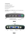
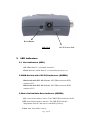
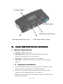
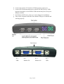
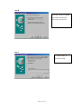
2-PORT USB KVM
SWITCH MIT USB 2.0 HUB
User's Manual
Ver:1.0
Table of Contents
I.
II.
Introduction… … … … … … … … … … … … … … … … … … … … … … ... 3
1.
Features… … … … … … … … … … … … … … … … … … … … … … … … … ..........3
2.
Package Contents… … … … … … … … … … … … … … … … … … … … … … … .. 3
Specifications… … … … … … … … … … … … … … … … … .… .… … … . 4
1.
General… … … … … … … … … … … … … … … … … … … … … … … ..… … ........ 4
2.
Connectors… … … … … … … … … … … … … … … … … … … … … … .… … … … 5
3.
LED Indicators… … … … … … … … … … … … … … … … … … … … .................. 6
3.1 Host Indicators… … … … … … … … … … … … … … … … … … … ................. 6
3.2 USB HUB switch with PC1/PC2 Indicators… … … … .… … ..… … … … … . 6
3.3Auto-switch /Auto Scan Indicator… … … … … … … … .… … … … … … … ... 6
III.
2-port USB KVM installation… … … … … … … … ...… … … … … .. 7
1.
System requirements… … … … … … … … … … … … … … … … … ..… ............... 7
2.
Hardware installation… … … … … … … … … … … … … … … … … ....… … … … .7
3.
Windows 98/98SE installation… … … … … … … … … … … … … … … … … … .. 9
4.
Driver installation… … … … … … … … … … … … … … … … … … ....… … … … .. 10
4.1 OS without driver installation… … … … … .… … … … … … ..… ..… … … … 10
4.2 Windows 98//98SE… … … … … … … … .… ..… … … … … … ..… .… … … … 10
5.
On-Screen-Display(OSD) utility software installation for Windows… … …
15
6.
Using the OSD Program.… … … … … … … … … … … … … … … ....… … … ..… 17
6.1 Activating the OSD Program … … … … … … … … … … … .… ...… … … ... 18
6.2 Interpreting the OSD window… … … … … … … … … … … … .… … … … … . 19
6.3 Switching the active host with the OSD Program … … … … ...… … … … … 20
6.4 Hiding and closing the OSD Program … … … … … … … .… … … … … … … 21
IV.
Operate the 2-port USB KVM… … … … … … … … ........................ 22
1.
Manual Switch by push button… … … … … … … … … … … … … … … … … … .. 22
1.1 Host selection… … … … … … … … … … … … … … … … … … … … … … … . 22
1.2 Activate Auto Switch Function… … … … … … … … … … … … … … … … .. 22
2.
Hot Key Switch(PS/2 Keyboard)… … … … … … … … … … … … … … … … … .. 22
3.
On-Screen-Display(OSD) Switch (Windows)… … … … … … … … … … … … 23
4.
AutoScan Function
… … … … … … … … … … … … … … … … … … … … … … 23
4.1 Activate Autoscan… … … … … … … … … … … … … … … … … … … … … … 23
4.2 Disable Autoscan… … … … … … … … … … … … … … … … … … … … … … 23
V.
5.
Sun Micro System Function Emulation … … … … … … … … … … … … … … … 24
6.
Hot Key definition table… … … … … … … … … … … … … … … … … … … … … 25
Application Notes… … … … … … … … … … … … … … … … … … … … . 26
Page 2 of 26
2-port USB KVM Switch
I.
Introduction
Thank you for choosing 2-port USB2.0 KVM Switch with PS/2 keyboard and
mouse ports, 3 USB 2.0 downstream ports, 2 upstream USB 2.0 ports, and 3VGA
ports. Now, you can operate 2 computers with 1 monitor, 1 keyboard, and 1 mouse
and share the USB devices connected to the KVM.
1.
Features
l Controls 2 PCs with one PS/2 or USB keyboard, one PS/2 or USB mouse, and
one monitor.
l Supports Windows 98/98SE/2000/Me/XP/VISTA, Linux Kernel 2.3 or later,
Mac OS9/OSX, Sun Micro Solaris 8 ( SUN BLADE 100)
l Supports 3 USB 2.0 downstream ports
l Supports 3 types of switching: hardware push button, hot keys on PS/2
keyboard, and On-Screen-Display (OSD) utility software (for Windows).
l OSD utility indicates:
i.
Power status of connected computer(s).
ii.
Active host computer.
l Supports VGA resolutions up to 2048x1536.
l Plug and Play. No driver is needed for PS/2 mouse and keyboard operation.
2.
Package Contents
The product you purchased should contain the following equipment and
accessories:
l 2 port USB 2.0 KVM Switch
l CD with users manual, On-Screen-Display(OSD) utility
l 2 sets of USB+VGA cables
Page 3 of 26
II.
1.
Specifications
General
Model
KC-221
Complies USB revision
USB 1.0, 1.1,2.0
Working PC status LED
2
USB upstream port
2
VGA IN port
2
VGA OUT port
1
USB downstream port
3
PS/2 keyboard port
1
PS/2 mouse port
1
Power Jack
DC-5V ( Optional for Power adaptor)
Reset button
1
Video resolution
2048 X 1536.
Hardware supported
OS Supported
Active PC selection
PC/Mac/Sun Micro
Windows 98/98SE/ME/2000/XP/Vista,
Mac OS9/OSX
Linux Kernel 2.3/above
Solaris 8/above
By push button
By hotkey (only in PS/2 keyboard)
By OSD utility( Windows )
Page 4 of 26
2. Connectors
l 1 Mini-din for PS/2 keyboard
l 1 Mini-din for PS/2 mouse
l
l
l
l
3 USB type A downstream connectors
2 USB type B upstream connectors
DC-5V Power Jack
Reset button
2 VGA input connectors (HDB15 Male), and one VGA output connector
(HDB15 Female).
USB 2.0
USB 2.0
USB 2.0
Front View
Push button
PC 1
USB
PC 1
Monitor IN
PC 2
Monitor IN
Rear View
Page 5 of 26
PC 2
USB
Reset Button
Side View
3.
DC-5V Power Jack
LED Indicators
3.1 Host Indicators (RED)
ON: When host PC is available and active.
Flash: Indicates which Host PC is selected but not power on
3.2HUB Switch with PC1/PC2 Indicators (GREEN)
Hub Switch with PC1 ON (Green): All USB downstream HUB
connect to PC1
Hub Switch with PC2 ON (Green): All USB downstream HUB
connect to PC2
3.3Auto-Switch/Auto-Scan Indicator (GREEN)
ON : Auto-Switch mode is active. The USB HUB will switch with PC
OFF: Auto-Switch mode is inactive. The USB HUB switch is
independent from PC and can be controlled by hot key.
Flash: Auto-Scan mode is active.
Page 6 of 26
PC2 HOST (RED)
PC1 HOST (RED)
HUB switch with PC1(Green)
Auto-Switch/ Auto-Scan ( Green )
III.
1.
HUB switch with PC2 ( Green )
2-port USB KVM Switch installation
System requirements:
·
·
Computer: USB port, VGA port
Operating System: Windows 98/98SE/2000/ME/XP/Vista, Mac
OS9/OSX, Linux Kernel 2.3 or Later, Solaris 8.
·
VGA Cable: 1 VGA female-to-male cable per computer
· USB Cable: 1 USB cable with one Type-A end and one Type-B end per
computer
· 2.
Hardware installation:
a. Connect the USB cable’
s Type-A end to the computer’
s USB port, and the
cable’s Type-B end to the KVM’
s PC1 USB upstream port.
b. Connect the VGA male-to-Female cable between the VGA port on the
computer’
s video card and the KVM’s PC1 monitor IN.
c. Repeat steps a thru b for the second computer, using the PC2 USB port and
monitor IN on the KVM.
Page 7 of 26
d. Connect the monitor VGA cable to KVM’s monitor output port.
e. Connect PS/2 keyboard and mouse to the KVM’
s PS/2 ports or USB
keyboard and mouse to the KVM’
s USB downstream ports (Except on
Windows 98/SE).
f. For Window 98/SE users, please go to next chapter for installation.
g. Turn on the computers and make sure that the USB port is enabled and
working properly.
USB 2.0
USB 2.0
USB 2.0
Push button
PC 1
USB
PC 1
Monitor IN
PC 2
Monitor IN
Page 8 of 26
PC 2
USB
Window 98/SE installation :
For Window 98 and 98/SE system users, you will need a different step of
installation. After the hardware installed, please follow up these steps to
install the KVM switch :
Step 1 : Remove PS/2 mouse and Keyboard devices from USB KVM Switch
and plug them into PC
Step 2 : Turn ON your PC
Step 3 : Use USB KVM Switch push button to switch the screen to the target
PC with Windows 98/SE system.
Step 4 : Follow up the chapter 4.Driver installation and finish the driver
installation
Step 5 : Remove PS/2 mouse and keyboard from PC and plug into USB
KVM Switch
Page 9 of 26
4. Driver installation:
4.1 OS without driver installation
No driver is needed for 2-port USB KVM Switch for the following
operating systems.
a. Windows ME/2000/XP
b. MAC OS9/OSX
c. Linux Kernel 2.3 or above
d. Sun Micro Solaris 8 or above
4.2 Windows 98/98SE:
After you connect 2-port USB KVM Switch to your PC, Win 98 will
automatically detect the device and prompt for the driver installation.
Please proceed the installation of driver by following the instructions
from Step A-H. Please have your Windows 98 CD ready.
Step A
A. Click “Next”to Continue
Page 10 of 26
Step B
B. Click “Next”to initiate
the search for the best
driver for your device.
Step
C
C. Click “Next”to
start and search.
Page 11 of 26
Step D
D. Click “OK”to continue
Step E
E. Click “Next”to continue
Page 12 of 26
Step F
F. Please specify the
location of the Windows
source disk and Click “OK”
to continue.
You may use “Browse”to
locate the driver.
(Ref Figure F)
*Note: Your hidclass.sys file might be located in a different directory from the figure
above.
Step G
G. Click “OK”to continue
Page 13 of 26
Step H
H. Click “Finish”, Windows
has finished installing the
USB Human Interface
Device driver for PS/2
keyboard & mouse.
Page 14 of 26
5. On-Screen-Display(OSD) utility software
installation for windows
Place the enclosed CD into your CD-ROM drive. The AutoManual screen will
automatically pop up on your monitor. Click the “Install OSD utility”button to
proceed. If the AutoManual screen does not present, then please use the file
explorer to choose the CDROM driver, and execute the AutoManual.exe.
Step A
A. Click “Next”to
continue the installation
Step B
B. Click “Next”to
continue
Page 15 of 26
Step C
C. Click “Yes”to continue
Step D
D. Click “Start”to continue
Step E
E. Click “Exit”
Page 16 of 26
6. Using the OSD Program
6.1 Activating the OSD program
l
From Start Menu \Program \KVM-OSD\KVM-OSD
l
OSD will start
Page 17 of 26
6.2 Interpreting the OSD window
The OSD indicates the status of the connections, host PC and the USB device.
Port connection status and
active host
Close Button
Hide Button
Host PC status
There are four different status:
A. “No PC Found”indicates no PCs are connected to the Pocket KVM or that
connected PCs are off.
B. “PC 1 On”indicates the first port has a PC connected to it, the PC is on and
the active host. The second port either has NO PC connected to it, or the PC is
connected, but not on.
Page 18 of 26
C. “PC 2 On”indicates the second port has a PC connected to it, the PC is on
and the active host. The first port either has NO PC connected to it, or the PC
is connected, but not on.
D. Both ports have PCs connected and on. The red letter and larger numeral
indicates the second port is the active host. The green letter and smaller
numeral indicates that the first port is NOT the active host, but is available for
connection.
6.3 Switching the active host using the OSD program
Using the mouse, simply click on the button of the port that you want as the
active host. The program will automatically switch the active host and the
numbers on the button will change accordingly.
Page 19 of 26
6.4 Hiding and closing the OSD program
l
When you click the “Hide”button, OSD program window will hide in
Taskbar.
l
When you click the “Close”button, OSD program will exit.
l
If OSD program is hidden in Taskbar, you can right click on the taskbar
icon to show or close the program.
IV. Operate the 2-port USB KVM Switch
1.
Manual Switch by push button
1.1 HOST selection
You can switch to the next available active USB host connection by pushing
the switch button on the 2-port USB KVM Switch
1.2
Activate Auto Switch Function
Page 20 of 26
You can activate Auto Switch Function by pushing the switch button for 3
second. The USB HUB will switch with Host together when Auto switch
function is enable.
2.
Hot Key Switch (PS/2 keyboard only, not available for
USB keyboard)
[Scroll] , [Scroll], [1] or
[Scroll], [Scroll], [2]
Switches to PC1: Scroll Lock + Scroll Lock + [ 1 ]
Switches to PC2: Scroll Lock + Scroll Lock + [ 2 ]
Switches to upper host: Scroll Lock + Scroll Lock + ↑
Switches to next host: Scroll Lock + Scroll Lock + ↓
Auto switch : Scroll Lock + Scroll Lock + [ H ]
Note: When using the two-step Hot Key sequences, the keys must be
pressed within 3 seconds, otherwise the Hot Key action will be
canceled. After pressing the Scroll key twice, the Scroll LED will start
blinking and wait for the Step 2 hotkey, after pressing any key or over 3
seconds, the keyboard LED will switch back to the original status.
3. On-Screen-Display (OSD) Switch (Windows only)
Activate the OSD and click the port number on the OSD. The active host will
change to the indicated port.
4. Auto-Scan Function
4.1 Activate Autoscan
Pressing Scroll + Scroll + [ S ] will activate AutoScan Mode.
4.2 Disable Autoscan
Page 21 of 26
Pressing any Keys excluding number key [ 1 ], [ 2 ], [ 3 ] and [ 4 ] to
turn off the AutoScan Mode and the monitor screen will jump back to
the original Host.
When you activate the Auto-Scan mode, the USB KVM Switch
alternates between the two PCs and displays them on the monitor.
Each PC can be displayed at 5, 10, 15, or 20 seconds:
4.3 Auto-Scan Interval
[n] *(Available only when Auto-Scan function is ON)
You can change the Auto-Scan interval by pressing the appropriate number
key or the number pad keys.
n
[1]
[2]
[3]
[4]
Scan Interval
5 sec.
10 sec.
15 sec.
20sec.
Page 22 of 26
5. Sun Micro system Function key emulation :
There are 16 special functions on the Sun Micro system keyboard, the
USB KVM Switch can emulate these function keys via the PS/2 keyboard
( it won’
t work on the USB keyboard ). Here is the mapping table for these
function operation. To active these emulation on the PS/2 keyboard, you
have to press the LEFT Window KEY first ( this key usually is located
between the left [Ctrl] and left [Alt]), then choice the second relative key.
Sun Micro System
Function Key
PS/2 Keyboard
Stop
L_Win & L_Alt
Props
L_Win & L_Ctrl
Compose
L_Win & L_Shift
Front
L_Win & F1
Open
L_Win & F2
Find
L_Win & F3
Again
L_Win & F4
Undo
L_Win & F5
Copy
L_Win & F6
Paste
L_Win & F7
Cut
L_Win & F8
Help
L_Win & F11
Power
L_Win & F12
Mute
L_Win & 1
Volume Down
L_Win & 2
Volume UP
L_Win & 3
Page 23 of 26
6. Hot key definition table
Step 1
Step2
Action
USB HUB Auto-Switch mode
Switches access to the computer which connecting to host1
Switches access to the computer which connecting to host2
Switch next host
Switch the upper one host
Switch the next one host
Switch the HUB to host 1
Switch the HUB to host 2
Start to Autoscan
*
AutoScan time interval is 5 seconds
(Available only when Auto-Scan function is ON)
*
AutoScan time interval is 10 seconds
(Available only when Auto-Scan function is ON)
No Scroll Key
*
Need
AutoScan time interval is 15 seconds
(Available only when Auto-Scan function is ON)
*
AutoScan time interval is 20 seconds
(Available only when Auto-Scan function is ON)
Page 24 of 26
V. Application Notes
1. IMPORTANT: Please select “Safely Remove Hardware”or “Eject”for
USB devices connected to any of the 3 downstream USB ports on the 2-port
USB KVM Switch before switching between the hosts. Switching hosts is
equivalent of removing the USB devices, which may damage your USB
devices or data if not removed properly by the OS.
2. The 2-port USB KVM Switch normally derives its own power from host
computer. When the 2-port USB KVM Switch and the USB port of computer
are connected, the LED will turn red, and the keyboard and mouse can
operate.
3. Unknown Device:
If the installation process has been completed and some of the devices still
don't work, please go to: Device Manager, check to see if any “Unknown
device”icons appear on the screen. You may need to “Remove”and “Refresh”,
then start the installation process again. If after trying the above mentioned
process and your device still does not work, please contact your retail dealer.
**Note: If you are connected to a heavy-duty HDD / CD-ROM, ‘unknown
device’might occur. Please plug in the appropriate adaptor for power
sufficiency.
Page 25 of 26
Disclaimer
Information in this document is subject to change without notice. The manufacturer does not make any
representations or warranties (implied or otherwise) regarding the accuracy and completeness of this document
and shall in no event be liable for any loss of profit or any other commercial damage, including but not limited to
special, incidental, consequential, or other damages.
No part of this document may be reproduced or transmitted in any form by any means, electronic or mechanical,
including photocopying, recording or information recording and retrieval systems without the express written
permission of the manufacturer.
All brand names and product names used in this document are trademarks, or registered trademarks of their
respective holders.
FCC Statement
This device generates and uses radio frequency and may cause interference to radio and television reception if
not installed and used properly. This has been tested and found to comply with the limits of a Class B computing
device in accordance with the specifications in Part 15 of FCC Rules. These specifications are designed to
provide reasonable protection against such interference in a residential installation. However, there is no
guarantee that interference will not occur in a particular installation. If this device does cause harmful interference
to radio or television reception, which can be determined by plugging the device in and out, the user can to try to
correct the interference by one or more of the following measures:
·
Reorient or relocate the receiving antenna.
·
Increase the separation between the device and receiver.
·
Connect the computer into an outlet on a circuit different from that to which the receiver is connected.
·
Consult the dealer or an experienced radio/TV technician for help.
Page 26 of 26