1
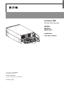
ENGLISH
HotSwap MBP
Maintenance Bypass
MBP6Ki
MBP11Ki
MBP11Ki31
Installation
and user manual
Copyright © 2013 EATON
All rights reserved.
Service and support:
Call your local service representative
SK-90510-Y4_EN
SAFETY INSTRUCTIONS
SAVE THESE INSTRUCTIONS. This manual contains important instructions
that should be followed during installation and maintenance of the MBP and UPS.
The HotSwap MBP models that are covered in this manual are intended for installation in an environment
within 0 to 40°C, free of conductive contaminant.
This equipment has been tested and found to comply with Class A UPS,pursuant to Part 15 of the FCC
Rules. These limits are designed to provide reasonable protection against harmful interference when the
equipment is operated in a commercial environment. This equipment generates, uses, and can radiate
radio frequency energy and, if not installed and used in accordance with the instruction manual, may cause
harmful interference to radio communications. Operation of this equipment in a residential area is likely
to cause harmful interference in which case the user will be required to correct the interference at his own
expense.
Certification standards (in use with UPS)
• Safety: IEC/EN 62040-1 / Ed.1: 2008.
• EMC: IEC 62040-2 / Ed.2: 2005
EN 62040-2 / Ed.2: 2006.
• Performance: IEC/EN 62040-3 / Ed.2.0: 2011.
• IEC 61000-4-2 (ESD): level 3.
• IEC61000-4-3(Radiatedfield):level3.
• IEC 61000-4-4 (EFT): level 4.
• IEC 61000-4-5 (Fast transients): level 4.
• IEC61000-4-6(Electromagneticfield):level3.
• IEC61000-4-8(Conductedmagneticfield):level4.
Special symbols
The following are examples of symbols used on the HotSwap MBP to alert you to important
information:
RISK OF ELECTRIC SHOCK - Observe the warning associated with the risk of electric shock symbol.
Important instructions that must always be followed.
This symbol indicates that you should not discard waste electrical or electronic equipment (WEEE)
in the trash. For proper disposal, contact your local recycling/reuse or hazardous waste center.
Information, advice, help.
Refer to the user manual of UPS.
Page 2
SK-90510-Y4_EN
Safety of persons
• The system has its own power source when connected to the UPS (UPS battery). Consequently,
the power outlets may be energized even if the system is disconnected from the AC power source.
Dangerous voltage levels are present within the system.
Itshouldbeopenedexclusivelybyqualifiedservicepersonnel.
• Theproductmustbeproperlygrounded,alwaysconnecttheearthwirefirst
Product safety
• The MBP connection instructions and operation described in the manual must be followed
in the indicated order. Disconnection and overcurrent protection devices shall be provided by others
for AC in/out circuits.
• CAUTION-Toreducetheriskoffire,theunitconnectsonlytoacircuitprovidedwithbranchcircuit
overcurrent protection (please refer to the UPS User Manual for current rating).
The upstream circuit breaker must be easily accessible.
The unit can be disconnected from AC power source by opening this circuit breaker, and if still
connected to UPS, by previously shutting down the UPS (refer to the UPS User Manual)
• Check that the indications on the rating plate correspond to your AC powered system and to the
actual electrical consumption of all the equipment to be connected to the system.
• Never install the system near liquids or in an excessively damp environment.
• Never let a foreign body penetrate inside the system.
• Never expose the system to direct sunlight or source of heat.
• If the system must be stored prior to installation, storage must be in a dry place.
• The admissible storage temperature range is -15ºC to +60ºC.
Special precautions
• The HotSwap MBP is designed to work with approved EATON UPS (contact your Eaton reseller for
more information)
• All repairs and service should be performed by AUTHORIZED SERVICE PERSONNEL ONLY.
There are NO USER SERVICEABLE PARTS inside the MBP.
SK-90510-Y4_EN
Page 3
ENGLISH
SAFETY INSTRUCTIONS
Contents
1. Introduction ....................................................................................... 5
1.1 Environmental protection ...................................................................................................5
2. Presentation ...................................................................................... 6
2.1 Standard positions .............................................................................................................6
2.2 Description / Panels ...........................................................................................................8
3. Installation ........................................................................................ 9
3.1 Inspecting the equipment..................................................................................................9
3.2 Unpacking the MBP...........................................................................................................9
3.3 Checking the accessory kit ................................................................................................9
3.4 Mechanical Mounting ...................................................................................................... 10
3.5 Installation requirements ................................................................................................. 10
4. Power cables connection ................................................................11
4.1 MBP6Ki............................................................................................................................ 11
4.2 MBP11Ki / MBP11ki31 – with common Normal and Bypass AC source ......................... 12
4.3 MBP11Ki / MBP11Ki31 – with separate Normal and Bypass AC source ......................... 13
5. Operations ....................................................................................... 15
5.1 UPS start-up with HotSwap MBP .................................................................................... 15
5.2 UPS replacement with HotSwap MBP ............................................................................ 16
5.3 UPS maintenance with HotSwap MBP ........................................................................... 18
6. Specifications .................................................................................. 19
Page 4
SK-90510-Y4_EN
Thank you for selecting an EATON product to protect your electrical equipment.
The HotSwap MBP range has been designed with the utmost care.
We recommend that you take the time to read this manual to take full advantage of the many features
of your MBP (Maintenance Bypass).
BeforeinstallingyourHotSwapMBPwithyourUPS,pleasereadfirstthesafetyinstructions.
Then follow the indications in this manual, which completes the UPS Installation and User Manual.
To discover the entire range of EATON products, we invite you to visit our web site at www.eaton.com/
powerquality or contact your EATON representative.
1.1 Environmental protection
EATON has implemented an environmental-protection policy.
Products are developed according to an eco-design approach.
Substances
This product does not contain CFCs, HCFCs or asbestos.
Packing
To improve waste treatment and facilitate recycling, separate the various packing components.
• The cardboard we use comprises over 50% of recycled cardboard.
• Sacks and bags are made of polyethylene.
• Packingmaterialsarerecyclableandbeartheappropriateidentificationsymbol
01
PET
Materials
Abbreviations
Number in
the symbols
Polyethylene terephthalat
PET
01
High-density polyethylene
HDPE
02
Polyvinyl chloride
PVC
03
Low-density polyethylene
LDPE
04
Polypropylene
PP
05
Polystyrene
PS
06
01
PET
Follow all local regulations for the disposal of packing materials.
End of life
EATON will process products at the end of their service life in compliance with local regulations. EATON
works with companies in charge of collecting and eliminating our products at the end of their service life.
Product
The product is made up of recyclable materials.
Dismantling and destruction must take place in compliance with all local regulations concerning waste.
At the end of its service life, the product must be transported to a processing center for electrical and
electronic waste.
SK-90510-Y4_EN
Page 5
ENGLISH
1. Introduction
2. Presentation
The Eaton® HotSwap MBP module makes it possible to service or even replace the UPS without affecting
the connected loads (HotSwap function).
You can safely eliminate the effects of UPS maintenance and guard the integrity of your equipment.
Providingoutstandingreliability,theEatonHotSwapMBPuniquebenefitsinclude:
• Easy and fast connection to UPS due to Input/Output and signal "all in one" patented connector
(Hotswap MBP 5/6kVA range)
•
"make before break" feature to allow full servicing (electrical power continuity) when switching from
UPS position to Bypass (and vice versa)
• Communication feature with UPS*: detection of MBP connection and switch position (Normal or Bypass)
(* works only with some approved EATON UPS - contact your Eaton reseller for more information)
• Load connection by both terminal blocks and IEC outlets (10A C13 and/or 16A C19 following MBP versions)
• Adjustable 19’’ Rack kit and multiple positions Tower installation kit provided
• Backed by worldwide agency approvals.
2.1 Standard positions
MBP6Ki
Tower installation
Rack installation
Page 6
Wall mounting
SK-90510-Y4_EN
MBP11Ki / MBP11Ki31
Tower installation
Rack installation
Description
Weight
(lb/kg)
Dimensions (inch/mm)
D xW x H
MBP6Ki
5.5 / 2.5
4.3 x 7.0 x 5.1 / 110 x 177 x 130
MBP11Ki
12.1 / 5.5
5.2 x 13.2 x 5.1 / 132 x 336 x 130
MBP11Ki31
12.1 / 5.5
5.2 x 13.2 x 5.1 / 132 x 336 x 130
H
H
D
SK-90510-Y4_EN
Wall mounting
W
D
W
Page 7
ENGLISH
2. Presentation
2. Presentation
2.2 Description / Panels
The HotSwap MBP has a manual Bypass rotary switch with two positions:
• UPS
the load is supplied by the UPS
•
Bypass
the load is supplied directly by the AC power source
On MBP11Ki and MBP11Ki31, it is possible to Bypass the load on a separate Bypass AC source
(see 4.3 for more details)
2 lights indicate the HotSwap MBP power status:
• "UPS supply" green light: when active, the UPS output is available, the Bypass switch can be safely
turned to UPS position
• "Bypass mode" red light: when active, indicates that the HotSwap MBP is on “Bypass mode” (Bypass
switch turned to Bypass position)
Normal AC source switch / Bypass AC source switch (following MBP versions):
Allow to safely switch off the AC source of the UPS, for UPS maintenance / replacing
MBP status detection:
A signal cable, with RJ11 connector to plug to the UPS, allows the communication to the UPS to manage
the MBP status, and the indication on UPS display panel of both following status:
• MBP connection to UPS
• Bypass switch position
Check the UPS user manual to check the compatibility of this feature, or contact Eaton reseller for more
information
MBP6Ki
5
4
(1) Input/Output terminal blocks
(2) Normal AC source switch
(3) Input/Output/MBP-Detection
connector to the UPS
(4) Manual Bypass switch
(5) (2) 16A outlets
(6) (3) 10A outlets
(7) UPS supply green light
(8) "Bypass" mode red light
3
8
7
6
1
2
MBP11Ki / MBP11Ki31
9 10
7
Page 8
8
1
2
6
4
3
5
(1) Input/Output terminal blocks
(2) Input/Output cables for
connection to the UPS
(3) Bypass terminal blocks for
connection to the UPS
(4) Normal AC source switch
(5) Bypass AC source switch
(6) Signal cable for MBP detection to
the UPS
(7) Manual Bypass switch
(8) (4) 16A outlets
(9) UPS supply green light
(10) "Bypass" mode red light
SK-90510-Y4_EN
3.1 Inspecting the equipment
If any equipment has been damaged during shipment, keep the shipping cartons and packing materials
forthecarrierorplaceofpurchaseandfileaclaimforshippingdamage.Ifyoudiscoverdamageafter
acceptance,fileaclaimforconcealeddamage.
Tofileaclaimforshippingdamageorconcealeddamage:
1) File with the carrier within 15 days of receipt of the equipment;
2) Send a copy of the damage claim within 15 days to your service representative.
3.2 Unpacking the MBP
Unpack the equipment and remove all the packing materials and shipping carton.
Discard or recycle the packaging in a responsible manner, or store it for future use.
Placethecabinetinaprotectedareathathasadequateairflowandisfreeofhumidity,flammablegas,
and corrosion.
Packing materials must be disposed of in compliance with all local regulations concerning waste.
Recycling symbols are printed on the packing materials to facilitate sorting.
3.3 Checking the accessory kit
• Verify that the following additional items are included with the MBP:
MBP6Ki
5
1
(1) Input/Output UPS cord Set
(2) Rack kit for 19-inch enclosures
(3) Fixation kit for Rack mounting
(including square nuts and
screws)
(4) Tower and Wall mounting kit
(including 2 ears and screws)
(5) Installation and User manual
3
4
2
MBP11Ki/ MBP11Ki31
(1) (2) cable glands for UPS Input
Bypass connection (option)
(2) Rack kit for 19-inch enclosures
(3) Fixation kit for Rack mounting
(including square nuts and
screws)
(4) Tower and Wall mounting kit
(including 2 ears and screws)
(5) Installation and User manual
5
1
3
SK-90510-Y4_EN
4
2
Page 9
ENGLISH
3. Installation
3. Installation
3.4 Mechanical Mounting
• Mount the MBP (on the UPS, on the EBM, in the rack or on the wall), see 2.1.
3.5 Installation requirements
Recommended protective devices and cable cross-sections
1. Recommended upstream protection
Refer to the UPS User Manual for circuit breaker current rating.
The circuit breaker has to be installed upstream the MBP Normal AC source.
2. Recommended cable cross-sections
Terminal
position
MBP6ki
Wire
function
L1
Phase
N (L2)
Neutral
(Phase)
Terminal wire
size rating
Minimum input wire
size rating
Tightening
torque
0.5-10 mm2
(20-8 AWG)
6 mm2 (10 AWG) 105°C
10 mm2 (8 AWG) 75°C
1 Nm
(10 lb in)
4-25 mm2
(12-4 AWG)
10 mm2 (8 AWG) 105°C
16 mm2 (6 AWG) 90°C
2 Nm
(18 lb in)
4-25 mm2
(12-4 AWG)
10 mm2 (8 AWG) 105°C
16 mm2 (6 AWG) 90°C
2 Nm
(18 lb in)
Ground
MBP11ki
L1
Phase
N (L2)
Neutral
(Phase)
Ground
MBP11ki31
L1
Phase
L2
Phase
L3
Phase
N
Neutral
Ground
Copper wire, solid or stranded.
Page 10
SK-90510-Y4_EN
Thistypeofconnectionmustbecarriedoutbyqualifiedelectricalpersonnel.
Before carrying out any connection, check that the upstream protection device (Normal AC source)
is open "O" (Off).
Before proceeding to connect the HotSwap MBP to the UPS, make sure the UPS has been properly shut
down (refer to the UPS user manual).
Always connect the ground wire first.
4.1 MBP6Ki
1. Connect the 2 power cables of I/O cord Set (1) to the UPS I/O terminal blocks, following color coding on
the cables and the UPS I/O cover (blue for UPS Input / red for UPS Output) – refer to the UPS user manual
to check the UPS terminal blocks connection.
2. Connect the MBP detection cable from the I/O cord Set (1) tothespecificUPSconnector
(MBP detect, refer to UPS User Manual).
Only with compatible EATON UPS, contact your Eaton reseller for more information.
3. Slide the MBP I/O cover (2) after removing the 4 screws, to access to MBP terminal blocks.
4. Insert the Normal AC source cable through the cable gland.
5. Connect the wires to the Normal AC source (Input) terminal blocks.
6. Insert the Output cable through the cable gland.
7. Connect the wires to the Output terminal blocks.
8. Tighten the cable glands.
9. Slide back and secure the MBP I/O cover (2) with the 4 screws.
10. Connect the I/O cord Set (1) connectortotheMBP,andsecureitbyfixingthe2lockingscrews.
1
to UPS output
RJ11 MBP detection
2
to UPS input
Utility
Power
Load
L1 N t L1 N t
L1 N t L1 N t
OUTPUT
2
OUTPUT
INPUT
Output cable
SK-90510-Y4_EN
INPUT
2
Normal AC Source
cable
Page 11
ENGLISH
4. Power cables connection
4. Power cables connection
4.2 MBP11Ki / MBP11ki31 – with common Normal and Bypass AC source
1. Connect the 2 integrated power cables (1) to the UPS I/O terminal blocks, following color coding on the
cables and the UPS I/O cover (blue for UPS Input / red for UPS Output) – refer to the UPS user manual to
check the UPS terminal blocks connection
2. Connect the MBP detection cable (2)tothespecificUPSconnector(MBPdetect,refertotheUPSUser
Manual)
Only with compatible EATON UPS, contact your Eaton reseller for more information.
3. Slide the MBP I/O cover (3) after removing the 5 screws, to access to MBP terminal blocks
4. Insert the Normal AC source cable through the cable gland
5. Connect the wires to the Normal AC source (Input) terminal blocks (do not remove the Input Bypass AC
jumper (4) and the UPS Input Bypass jumper inside the UPS I/O cover (refer to the UPS User Manual)
6. Insert the Output cable through the cable gland
7. Connect the wires to the Output terminal blocks
8. Tighten the cable glands
9. Slide back and secure the MBP I/O cover (3) with the 5 screws
2
RJ11 MBP detection
1
to UPS input
to UPS output
3
Utility Power
Load
MBP11Ki
L1 L1 N t
L1 N t
OUTPUT
INPUT
L1 L1 N t
L1 N
t
L1 N t
OUTPUT
INPUT BP
INPUT
L1 N
t
INPUT BP
3
3
4
4
Output cable
Normal AC Source
cable
MBP11Ki31
t
L1 N t
L1 N
OUTPUT
INPUT BP
L1 N
OUTPUT
INPUT BP
3
3
4
4
Output cable
Page 12
t
L1 N t
Normal AC Source
cable
SK-90510-Y4_EN
4.3 MBP11Ki / MBP11Ki31 – with separate Normal and Bypass AC source
1. Slide the MBP Bypass Input cover (5) after removing the 3 screws.
2. Punch the UPS Bypass Input knockout of the MBP Bypass Input cover
(5) and insert a provided cable gland inside.
5
5
3
5
3. Insert a power cable (refer to 3.5 for cable cross-section) through
the cable gland of the MBP Bypass Input cover (5) (cable not
provided in the packaging).
L1 N t
L1 N t
INPUT BP
INPUT BP
5
5
4. Connect the wires to the "Input BP" terminal blocks of the MBP
Bypass Input cover (5).
5. Tighten the cable gland.
6. Slide back and secure the MBP Bypass Input cover (5) with the 3
screws.
to UPS
Bypass input
7. Connect the 2 integrated power cables (1) and the previously installed Bypass Input power cable to the
UPS I/O terminal blocks, following color coding on the cables and the UPS I/O cover
(blue for UPS Input / red for UPS Output / yellow for UPS Input Bypass) – refer to the UPS user manual to
check the UPS terminal blocks connection (do not forget to also remove the Input Bypass AC jumper
on UPS).
8. Connect the MBP detection cable (2)tothespecificUPSconnector(MBPdetect,refertotheUPSUser
Manual)
Only with compatible EATON UPS, contact your Eaton reseller for more information.
9. Slide the MBP I/O cover (3) after removing the 5 screws, to access to MBP terminal blocks
10. Remove the Input Bypass AC jumper (4)
11. Punch the Bypass AC Source knockout of the MBP I/O cover (3) and insert a
provided cable gland inside
3
MBP11Ki
3
MBP11Ki31
L1 L1 N t
4
L1 N t
OUTPUT
3
SK-90510-Y4_EN
INPUT
L1 L1 N t
L1 N
t
INPUT BP
4
L1 N t
OUTPUT
INPUT
L1 N
t
INPUT BP
3
Page 13
ENGLISH
4. Power cables connection
4. Power cables connection
12. Insert the Normal AC source cable through the cable gland
13. Connect the wires to the Normal AC source (Input) terminal blocks
14. Insert the Bypass AC source cable through the cable gland
15. Connect the wires to the Bypass AC source (Input BP) terminal blocks
16. Insert the Output cable through the cable gland
17. Connect the wires to the Output terminal blocks
18. Tighten the cable glands
19. Slide back and secure the MBP I/O cover (3) with the 5 screws
2
1
RJ11 MBP detection
to UPS output
to UPS input
5
to UPS Bypass
input
Bypass Power
3
Utility Power
Load
MBP11Ki
L1 L1 N t
L1 N t
OUTPUT
INPUT
L1 L1 N t
L1 N
t
L1 N t
OUTPUT
INPUT BP
INPUT
L1 N
t
INPUT BP
3
3
Output cable
Normal AC
Source cable
MBP11Ki31
L1 N t
OUTPUT
3
Bypass AC
Source cable
L1 N t
INPUT BP
L1 N t
OUTPUT
L1 N t
INPUT BP
3
Output cable
Normal AC
Source cable
Page 14
Bypass AC
Source cable
SK-90510-Y4_EN
5.1 UPS start-up with HotSwap MBP
Verify that the total equipment ratings do not exceed the UPS capacity to prevent an overload alarm.
1. Check that the UPS is correctly connected to the HotSwap MBP (see previous chapter 4)
If the UPS if equipped with outlets, those outlets can no longer be used (loads can only be connected to the
MBP outlets or the MBP Output terminal blocks).
2. Verify that the MBP terminal blocks are connected to the AC source, and to the Bypass AC source (*)
UPS
BYPASS
3. Check that the MBP manual Bypass switch is to the "Bypass" position
4. Set the upstream circuit breaker (not provided) to the "I" position (On) to switch On the utility power, and
also set the Bypass source upstream circuit breaker (not provided) to the "I" position (On) to switch on the
Bypass power (*)
5. Verify that the “Bypass mode”red light of the MBP goes On, indicating that the load is now powered
by the AC source, or Bypass AC source (*)
6. Set the Normal AC source switch and the Bypass AC source switch (*) of the MBP to the "I" position
7. Verify that the UPS is correctly powered (UPS display panel illuminates)
8. Press the UPS “ON” button to start the UPS
9. Put the UPS in “internal Bypass mode” (refer to the UPS User Manual)
10. Verify that the UPS is on Bypass mode by checking UPS display panel (refer to the UPS user manual)
11. Verify that the “UPS mode” green light of the MBP goes On, indicating that the UPS output power is
available on the MBP
Important: do not continue to next step if the "UPS mode" green light of the MBP is still Off
(the load will be lost)
UPS
BYPASS
12. Set the MBP manual Bypass switch to the "UPS" position: the "Bypass mode" red light of the MBP goes
Off, indicating that the load is now powered by the UPS
13. Put the UPS in "normal mode" (refer to the UPS User Manual)
14. Check that the UPS is in Online mode by checking UPS display panel (refer to the UPS user manual)
the load is now protected by the UPS
(*) only in case of Bypass AC source option connected (MBP11Ki and MBP11Ki31 only).
SK-90510-Y4_EN
Page 15
ENGLISH
5. Operations
5. Operations
5.2 UPS replacement with HotSwap MBP
UPS Removing (please follow the MANDATORY step below):
MBP6Ki:
UPS
BYPASS
1. Put the UPS in "internal Bypass mode" (refer to the UPS user manual)
2. Verify that the UPS is on Bypass mode by checking UPS display panel (refer to the UPS user manual)
3. Set the MBP manual Bypass switch to "Bypass" position. The "Bypass mode" red light of the MBP goes
On, indicating that the load is supplied directly by AC source
4. Switch the Normal AC source switch of the MBP to the "0" position and wait 30 seconds
5. UPS stops, the UPS can now be disconnected, as described below:
• First disconnect the I/O cord Set (1) from the MBP, after removing the 2 screws.
1
• After opening the UPS I/O terminal blocks cover, check if hazardous voltage is no longer present on UPS
terminal blocks by using an electrical safety tester.
• Disconnect the 2 power cables, and the MBP detection cable (following UPS versions), of the MBP I/O
cord Set (1).
• Replace the UPS.
Hazardous voltage and lost load risk: do not manipulate the MBP manual Bypass switch without UPS
connected via the I/O cord Set (1).
Page 16
SK-90510-Y4_EN
MBP11Ki / MBP11Ki31:
UPS
BYPASS
1. Put the UPS in "internal Bypass mode" (refer to the UPS user manual)
2. Verify that the UPS is on Bypass mode by checking UPS display panel (refer to the UPS user manual)
3. Set the MBP manual Bypass switch to "Bypass" position. The "Bypass mode" red light of the MBP goes
On, indicating that the load is supplied directly by AC source, or Bypass AC source (*)
4. Switch the Normal AC source switch and the Bypass AC source switch (*) of the MBP to the "0"
position and wait 30 seconds
5. UPS stops, the UPS can now be disconnected, as described below:
• First lock the Normal AC source switch (4) and the Bypass AC source switch (5) (*) of the MBP to the "0"
position(theswitchprotectionframesareabletofitacabletieorametalliclocker).
4
5
• After opening the UPS I/O terminal blocks cover, check if hazardous voltage is no longer present on UPS
terminal blocks by using an electrical safety tester.
• Disconnect the MBP power power cables, and the MBP detection cable (following UPS versions).
• On each MBP power cables just disconnected from the UPS, link the wires together (line and neutral
wires linked to ground wire).
• Replace the UPS
Hazardous voltage and lost load risk: do not manipulate the MBP manual Bypass switch without UPS
connected to the MBP power cables
(*) only in case of Bypass AC source option connected (MBP11Ki and MBP11Ki31 only).
SK-90510-Y4_EN
Page 17
ENGLISH
5. Operations
5. Operations
Return to normal operation:
1. Check that the new UPS is correctly connected to the MBP, as described below:
MBP6Ki:
• After opening the UPS I/O terminal blocks cover, connect to UPS the 2 power cables, and the MBP
detection cable (following UPS versions), of the MBP I/O cord Set (1)– see 4.1 for more details
• Connect the I/O cord Set (1)connectortotheMBP,andsecureitbyfixingthe2lockingscrews
MBP11Ki / MBP11Ki31 :
• First check that the Normal AC source switch (4) and the Bypass AC source switch (5) (*) of the MBP
are still locked to the "0" position
• Remove the previously installed safety wires links on each MBP power cables
• After opening the UPS I/O terminal blocks cover, connect to UPS the MBP power cables, and the MBP
detection cable (following UPS versions) – see 4.2 and 4.3 for more details
• Unlock the Normal AC source switch (4) and the Bypass AC source switch (5) (*) of the MBP.
2. Set the Normal AC source switch and the Bypass AC source switch (*) of the MBP to the "I" position
3. Verify that the UPS is correctly powered (UPS display panel illuminates)
4. Press the UPS "ON" button to start the UPS
5. Put the UPS in "internal Bypass mode" (refer to the UPS User Manual)
6. Verify that the UPS is on Bypass mode by checking UPS display panel (refer to the UPS user manual)
7. Verify that the "UPS mode" green light of the MBP goes On, indicating that the UPS output power is
available on the MBP.
Important: do not continue to next step if the "UPS mode" green light of the MBP is still Off
(the load will be lost)
UPS
BYPASS
8. Set the MBP manual Bypass switch to the "UPS" position: the "Bypass mode" red light of the MBP goes
Off, indicating that the load is now powered by the UPS
9. Put the UPS in "normal mode" (refer to the UPS User Manual)
10. Check that the UPS is in Online mode by checking UPS display panel (refer to the UPS user manual)
the load is now protected by the UPS
5.3 UPS maintenance with HotSwap MBP
UPS
BYPASS
Go to maintenance Bypass operation (please follow the MANDATORY steps below):
1. Put the UPS in "internal Bypass mode" (refer to the UPS user manual)
2. Verify that the UPS is on Bypass mode by checking UPS display panel (refer to the UPS user manual)
3. Set the MBP manual Bypass switch to "Bypass" position. The "Bypass mode" red light of the MBP goes
On, indicating that the load is supplied directly by AC source, or Bypass AC source (*)
4. Proceed to maintenance operations on UPS (refer to the UPS User Manual)
Return to normal operation:
1. Verify that the UPS is on Bypass mode by checking UPS display panel (refer to the UPS user manual)
2. Verify that the "UPS mode" green light of the MBP is On, indicating that the UPS output power is
available on the MBP
Important: do not continue to next step if the "UPS mode" green light of the MBP is Off
(the load will be lost)
UPS
Page 18
BYPASS
3. Set the MBP manual Bypass switch to the "UPS" position: the "Bypass mode" red light of the MBP goes
Off, indicating that the load is now powered by the UPS
4. Put the UPS in "normal mode" (refer to the UPS User Manual)
5. Check that the UPS is in Online mode by checking UPS display panel (refer to the UPS user manual)
the load is now protected by the UPS
(*) only in case of Bypass AC source option connected (MBP11Ki and MBP11Ki31 only).
SK-90510-Y4_EN
MBP6Ki
MBP11Ki
MBP11Ki31
Input
Terminal blocks
N/A
Nominal voltage
Frequency
Input nominal
current
Maximal power
Safety
EMC
Performance
ESD
Radiatedfield
EFT
Fast transients
Electromagnetic
field
Conducted
magneticfield
Input Bypass
Terminal Blocks
Terminal Blocks
Output
4 IEC 16A + Terminal blocks 4 IEC 16A + Terminal blocks
2 IEC 16A + 3IEC 10A +
Terminal blocks
Overall dimensions D x W x H (inch / mm)
5.6 x 7.0 x 5.1 /
6.8 x 13.2 x 5.1 /
142 x 177 x 130
172 x 336 x 130
Weight (lb / kg)
5.5 / 2.5
12.1 / 5.5
Performance
200 - 240 V ~
200 - 240 V ~
50/60 Hz
30A
50A
6000 VA
11000 VA
Standards (HotSwap MBP used with UPS)
IEC/EN 62040-1 / Ed.1: 2008
IEC 62040-2 / Ed.2: 2005 EN 62040-2 / Ed.2: 2006
IEC/EN 62040-3 / Ed.2.0: 2011.
IEC 61000-4-2 : level 3.
IEC 61000-4-3 : level 3.
IEC 61000-4-4 : level 4.
IEC 61000-4-5 : level 4.
IEC 61000-4-6 : level 3.
6.9 x 13.2 x 5.1 /
176 x 336 x 130
12.1 / 5.5
350 - 430 V ~
50A
11000 VA
IEC 61000-4-8 : level 4.
Marking
CE
Environment
SK-90510-Y4_EN
Operating
temperature
0 to 40°C (32 to 104°F)
Storage
temperature
Transit temperature
Humidity
Operation Altitude
Transit Altitude
-15 to 60°C (5 to 140°F)
-25 to 55°C (-13 to 130°F)
0 to 95% no condensing
Up to 3,000 meters (9,843 ft) above sea level with 10% derating per 1000m
Up to 10,000 meters (32,808 ft) above sea level
Page 19
ENGLISH
6. Specifications
Page 20
SK-90510-Y4_EN