1
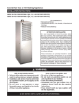
Counterflow Gas or Oil Heating Appliance
Owners Manual/Installation Instructions
CMF80-PG Convertible (65, 75, and 90 KBTU/H Inputs),
CMF 100-PG (90 KBTU/H Input)
CMF80-PO Convertible (65, 75, and 90 KBTU/H Inputs),
CMF 100-PO (90 KBTU/H Input)
Read all instructions carefully before beginning the installation. Read all labels and tags
on the furnace carefully and follow all precautions outlined on those labels and tags.
FOR YOUR SAFETY
Do not store or use gasoline or other
flammable vapors and liquids in the
vicinity of this or any other appliance.
! WARNING:
Improper installation, alteration, service or maintenance can cause injury
or property damage. Refer to this
manual for assistance or consult a
qualified installer, service agency, or
the gas supplier for additional information.
FOR YOUR SAFETY
WHAT TO DO IF YOU
SMELL GAS
• Do not try to light any appliance.
• Do not touch any electric switch; do not
use any phone in your building.
• Immediately call your gas supplier from a
neighbor’s phone. Follow the gas supplier’s
instructions.
• If you cannot reach your gas supplier, call
the fire department.
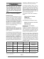
Rated
BTUH
Input
Output
CMF-PG CMF-PO CMF-PG
80 CONV. 80 CONV.
100
75,000
75,000
90,000
56,000
60,000
68,000
CMF-PO
100
90,000
72,000
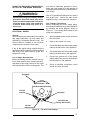
GENERAL
CMF furnaces are high quality, direct vent
furnaces used for manufactured housing, rec-
reational vehicle, and residential† applications.
These furnaces are offered in either power gas
(designated by PG) or power oil (designated by
PO) models. The power gas models are designed for operation with either natural or propane (LP) gas.
The CMF series is convertible from power oil to
power gas, and vice versa. Furthermore, the
firing rate of the CMF80 Convertible Series can
be changed using a certified NORDYNE
conversion kit field-installed by a qualified service
technician. Refer to the “Firing Rate Conversion”
section later in these instructions for more
information on the firing rate change.
These furnaces are certified to the UL307
standards (UL 307A for oil models; UL 307B for
gas models), and can be installed in a variety of
applications, as shown in Table 1. This furnace
is not to be used for temporary heating of
buildings or structures under construction.
! WARNING:
This furnace must be installed by a qualified installing agency and in accordance
with applicable local codes and ordinances that govern this type of equipment. Failure to properly install the furnace, base assembly, and venting system as described herein may damage the
equipment and/or the home, can create a
fire or asphyxiation hazard, violates U.S.
listing requirements, and will void the
warranty. This furnace is NOT approved
for installation with split system air conditioning. Use a NORDYNE packaged air
conditioning system.
Installations (Manufactured Home Sites,
Communities, and Set-ups), ANSI 225.1.
! WARNING:
Do not use this appliance if any part has
been submerged under water. Immediately call a qualified service technician to
inspect the appliance and to replace any
part of the control system and any gas
control that has been submerged under
water.
All residential installations (Refer to Table 1)
must conform with these instructions, all
applicable local building codes, ANSI Z223.1/
NFPA 54 (National Fuel Gas Code), ANSI/
NFPA 31 (Installation of Oil-Burning Equipment),
ANSI/NFPA70 (National Electrical Code), and
NFPA 211 (Chimneys, Fireplaces, Vents, and
Solid Fuel-Burning Appliances).
The National Fuel Gas Code is available by
writing:
INSTALLATION REQUIREMENTS
Equipment Check
All units are securely packaged at the time of
shipment and should be carefully inspected
upon arrival for damage. Claims for damages
(apparent or concealed), shortage in shipment,
or nondelivery should be filed immediately against
the carrier by the consignee. The carrier is
responsible for making prompt inspection of
damage and for a thorough investigation of
each claim. The manufacturer will not accept
claims for transportation damage.
NFPA publications are available by writing:
Requirements and Codes:
Installer shall be familiar with and comply with all
codes and regulations and applicable to the
installation of these heating appliances and
related equipment.
Combustion Air and Ventilation
Requirements
Provisions for adequate combustion air and
ventilation air must be in accordance with the
ANSI Z223.1/NFPA 54, (National Fuel Gas
Code), ANSI/NFPA 31 (Installation of Oil Burning
Equipment), and all applicable local codes.
All manufactured housing installations must
conform with these instructions, all applicable
local codes, ANSI Z223.1/NFPA 54 (National
Fuel Gas Code), ANSI/NFPA 31 (Installation of
Oil Burning Equipment), ANSI/NFPA 70
(National Electrical Code), the Manufactured
Home Construction and Safety Standard, Title
24 CFR, part 3280, or when this standard is not
applicable, the standard for Manufactured Home
Type of
Installation
Manufactured
Housing or
Recreational Vehicle
Residential
Residential
Residential
American National Standards
Institute, Inc.
1430 Broadway
New York, NY 10018
National Fire Protection Association
Batterymarch Park
Quincy, ME 02269
Depending upon the type of installation (See
Table 1), the CMF furnace can draw the
combustion air either from outside the home
(direct vent) or from the space being conditioned.
A direct vent system is one in which the flue
products are exhausted to and the combustion
air is drawn from outside the house. A direct
vent system can also be referred to as a sealed
combustion system.
Ducted
Application
Direct Vent
System Required
Furnace
Base Used
Flue Products
Exhausted By
Yes
Yes
MA-100 or MA-200
Universal Base
NORDYNE SRJ
Roofjack Only
†
Yes
Yes
MA-100 or MA-200
Universal Base
NORDYNE SRJ Roofjack or
an Existing Chimney*
†
Yes
Yes
CB-200A Cottage
Base
NORDYNE SRJ Roofjack or
an Existing Chimney*
†
No
No
CB-200A Cottage
Base
NORDYNE SRJ Roofjack or
an Existing Chimney*
†Residential is only defined as a single-story non-manufactured housing installation.
*Refer to the "Venting Requirements" section later in these instructions for more details on properly venting this appliance
through an existing chimney.
Table 1
2
For direct vent applications either the combustion
air duct provided with the MA Series base kit or
the direct vent kit can be used. The direct vent
kit must be ordered separately. Only for a
special CB-200A cottage base installation can
the CMF draw the combustion air from the
conditioned space. The CB-200A cottage base
kit must be ordered separately. Refer to the
replacement parts listing provided with the
furnace to order the direct vent kit or the cottage
base kit. Follow the instructions provided with
the kits for proper installation.
When unsure about combustion air supply
availability, a direct vent system should be
used. For small rooms, confined spaces, tight
construction or similar situations in which the
combustion air requirements of the furnace
might not be met, a direct vent system must be
used. The air openings in the door of the unit and
the warm air registers from the ductwork or
base must not be restricted.
Combustion air must not be drawn from a
contaminated atmosphere.
Excessive
exposure to contaminated combustion air will
result in safety and performance related
problems. Some examples of chemical
contaminants are chlorine, fluorine, and sulfur,
which can be found in a wide variety of some
common commercial and household products.
The installation of the furnace must allow for an
adequate supply of combustion air. The
combustion air opening of the furnace must be
designed and located to prevent blockage by
snow.
When drawing the combustion air from
underneath the home, ensure that a vent or duct
of at least 18 square inches of free area is
provided from outside. Check to ensure that the
combustion air opening is unobstructed. When
using the combustion air duct, ensure that it
extends through the floor. When using the
direct vent kit, the combustion air opening must
be located in the same pressure zone as the flue
exit of the roof jack or chimney. Refer to the
instructions provided with the direct vent kit for
more information.
Venting Requirements — Manufactured
Housing Installations
For all manufactured housing applications, the
CMF furnace must be vented using the SRJ
series roofjack. The instructions for selecting
the proper roofjack for your installation are
detailed later in these instructions.
Venting Requirements — Residential
Installations
! WARNING:
This furnace is not to be connected to a
chimney flue serving a separate appliance designed to burn solid fuel.
For residential applications (Refer to Table 1),
the CMF furnace may be vented through the
SRJ series roofjack or through an existing
chimney. If the SRJ roofjack is to be used, then
the instructions for selecting the proper roofjack
for your installation are detailed later in these
instructions. If venting through an existing
chimney, then the venting system used must be
in accordance with these instructions, all
applicable local building codes, ANSI Z223.1/
NFPA 54 (National Fuel Gas Code), ANSI/
NFPA 31 (Installation of Oil-Burning Equipment),
and NFPA 211 (Chimneys, Fireplaces, Vents,
and Solid Fuel-Burning Appliances).
! WARNING:
When venting through a chimney, check
the chimney for soot, leaks, obstructions, and proper installation.
The materials used to construct the venting
system must be capable of withstanding
exposure to temperatures of at least 700 degrees
F. The existing chimney servicing this furnace
must be vertical. Horizontal distances to an
existing chimney must be as short as possible,
and the connecting pipe must slope upward to
the chimney at not less than a 45 degree angle.
The total length of the sloping pipe must not
exceed 6 feet. The venting system must have
no obstructions or sharp bends where soot and
other foreign matter can accumulate.
If an inspection determines that the chimney is
obstructed, the chimney must be cleaned.
Furthermore, the connecting flue pipe must be
cleaned or replaced.
For ONLY a CMF power oil furnace installation
vented into an existing chimney, a barometric
damper can be installed at the vent connection
of the furnace to regulate the draft. The barometric
damper must be properly installed per the
manufacturer’s instructions. Refer to all
applicable codes to determine whether or not a
3
barometric damper can be used for your CMF
power oil furnace installation. The barometric
damper used must be installed such that air
from the conditioned space can only enter the
flue passageway. Do not use a double acting
barometric damper. All flue pipe joints should be
fastened with sheet metal screws for rigidity.
The chimney height, required draft, and number
of appliances served by the chimney must be
in accordance with all applicable codes. To
prevent down draft, the chimney should extend
at least two feet above the peak of the roof.
It is recommended that the furnace flue serve
no other appliances. When the chimney serves
only the furnace, the flue area must be sized
according to all applicable codes. The minimum
internal area of the flue must be equal to at least
the area of the furnace flue exit.
When two or more appliances must vent through
a common flue, the area of the common flue
should be sized in accordance with all applicable
codes.
When an existing furnace is removed or replaced
in a venting system, then the venting system
may not be properly sized to vent the attached
appliances. The venting system must be
checked to ensure proper venting. Improperly
sized venting systems can result in the formation
of condensate, leakage, spillage, et cetera.
Refer to the ANSI Z223.1/NFPA 54, (National
Fuel Gas Code), and ANSI/NFPA 31( Installation
of Oil Burning Equipment) for correcting any
improperly operating venting system.
The following steps shall be followed with each
appliance connected to the venting system
placed in operation, while any other appliances
connected to the venting system are not in
operation:
(a) Seal any unused openings in the venting
system.
(c) In so far as is practical, close all building
doors and windows and all doors between
the space in which the appliance(s) connected to the venting system are located
and other spaces of the building. Turn on
clothes dryers and any appliance not connected to the venting system. Turn on any
exhaust fans, such as range hoods and
bathroom exhausts, so they shall operate
at maximum speed. Do not operate a
summer exhaust fan. Close fireplace
dampers.
(d) Follow the lighting instructions. Place the
appliance being inspected in operation.
Adjust thermostat so appliance shall operate continuously.
(e) Test for draft hood equipped appliance
spillage at the draft hood relief opening
after 5 minutes of main burner operation.
Use the flame of a match or candle.
(f)
After it has been determined that each
appliance connected to the venting system properly vents when tested as outlined above, return doors, windows,
exhaust fans, fireplace dampers and any
other gas burning appliance to their previous conditions of use.
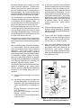
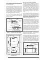
Flashing
Barrel
Ceiling Plate
Vent
Ventilation
Knock-Out
Return Air
Grille and
Filter
Power Supply
Connection
(b) Inspect the venting system for proper size
and horizontal pitch, as required in the
ANSI Z223.1/NFPA 54, (National Fuel Gas
Code) and ANSI/NFPA 31 (Installation of
Oil
Burning Equipment), and these instructions. Determine
that there is no blockage or restriction,
leakage, corrosion
or other deficiencies which could cause an
unsafe condition.
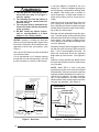
ROOF JACK
ASSEMBLY
Access
Door
FURNACE
ASSEMBLY
Combustion Air
Adapter (Not Shown)
is to be Installed
Over Combustion
Air Duct
Base Pan
Fuel Line
Feeder Duct
DUCT
CONNECTOR
Combustion
Air Duct
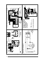
Figure 1. Typical Furnace Installation for
Manufactured Housing Applications
4
(g) If improper venting is observed during any
of the above tests, the venting system
must be corrected.
Unit Location and Clearance to Adjacent
Material Requirements
The unit must be installed in a level position. The
furnace must be installed with the minimum
clearances from adjacent materials as stated in
Table 2. Additional clearance should be provided
to permit servicing of filters, blower, motors,
controls, combustion air connections, and vent
connections.
Closet
Installation
0"
0"
6"**
17"
6"
1/4"
1"
0"
ALL MODELS
Sides
Back
Front
Top
Vent
Duct within 3’ from Furnace
Plenum
Roof Jack Barrel
Alcove
Installation
0"
0"
18"
17"
6"
1/4"
1"
0"
** See Item K in the "Closet Installation of
Furnace" section later in these instructions for clearance less than 6".
Table 2. Minimum Clearances
to Adjacent Materials
UNIT INSTALLATION
These instructions are intended for the use of
qualified individuals specially trained and
experienced in installation of this type equipment
and related system components. Installation
and service personnel are required by some
governing bodies to be licensed. Persons not
qualified should not attempt to install this
equipment or interpret these instructions.
MA-200 Base Installation
The MA-200 base is designed for O.E.M. and
replacement installation of the CMF series furnace (see Figures 2 and 3). The warm air duct
system should be designed so the duct static
pressure external to the furnace does not
exceed the static pressure listed on the furnace
data label.
Use the base pan to mark the 12-1/8" x 12-1/
8" center opening for the feeder duct. When the
4" offset feeder duct is used, the floor opening
will be offset 4 inches from the opening in the
main duct. If using the combustion air duct,
select and knock out the combustion air opening to be used. Then mark the 2-1/4" x 7-1/4"
opening for the combustion air duct.
Cut the opening for the feeder duct 14-1/8" x 141/8" in flooring (cutting opening 1" larger all the
way will allow the flanges on the underside of the
base pan to fit in the opening).
If using the combustion air duct, cut the opening
for the duct about 1/8" larger than the marking
on the floor. Be sure to cut through all insulation
and the bottom board so that the combustion air
duct is unobstructed to outside air.
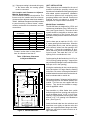
18-1/4
9-1/8
8-3/8
Drill an approximate 1" diameter hole for the fuel
line through the floor and bottom board to the
outside. Fuel lines are not supplied with the
furnace. They should be installed to comply
with all applicable codes.
12-1/8
Flue
Location
24-1/8
12-1/8
Feeder Duct
Opening
7-1/8 X 2-3/16 Knock-outs
Combustion Air
FRONT
Figure 2. MA-200 Base Pan
Drop transition or offset feeder duct upside
down through the floor opening and center the
top of the feeder duct in 14-1/8" x 14-1/8" floor
opening. Using the feeder duct as a guide, mark
and cut a 12" x 12" opening in the distribution
duct. (See Figure 3)
Insert the feeder tabs into the main duct and
bend them over tightly so that the main duct
edges are trapped between flanges and tabs.
Metal tape may also be used to ensure an air
tight connection.
5
Install the base pan around the feeder duct with
the (2) screws through the holes towards the
rear of the base pan.
Slit the corners of the feeder duct down to the
top of the base pan. While the top of the
distribution duct is pulled up with one hand, bend
down each side of the feeder duct tightly to the
base with the other hand. Trim the metal to allow
a one inch flange over the top of the base pan
and seal that flange with the metal tape.
If a “V” or “U”-box crossover system is to be
used, see the instructions provided with the
crossover system.
MA-100 Universal Base Installation
The MA-100 base is designed primarily for
replacement installation of the CMF series furnace where the manufactured home duct system may be small and restrictive to proper air
flow. The MA-100 base provides approximately four (4) inches of additional plenum
space before the discharge air enters the manufactured home duct system. (See Figures 4
and 5)
Use the bottom panel of the base assembly to
mark the 12-1/8" x 12-1/8" center opening for
the feeder duct. If using the combustion air duct,
select and knock out the combustion air opening to be used. Then mark the 2-1/4" x 7-1/4"
opening for the combustion air duct.
Bend Down 4 Sides
Slit 4 Corners
Base
TRANSITION
DUCT
Bend Over Tabs
Floor
Joists
Flange
Heater Duct Below Joists
Bend Down 4 Sides
Slit 4 Corners
Base
Floor
Joists
Flange
Bend Over Tabs
If using the combustion air duct, cut the opening
for the duct about 1/8" larger than the marking
on the floor. Be sure to cut through all insulation
and the bottom board so that the combustion air
duct is unobstructed to the outside air.
Heater Duct Below Joists
Figure 3. Transition and Offset Ducts
12-1/8
Cut the opening for the feeder duct 14-1/8" x 141/8" in flooring (cutting opening 1" larger all the
way around 12-1/8" x 12-1/8" template marking). This will allow the four flanges on the
underside of the panel to fit into the opening.
Drill a 1" hole for the fuel line through the floor and
bottom board to the outside. Fuel lines are not
supplied with the furnace. They should be
installed to comply with local codes.
Put the bottom base panel in place (See Figure
5). Drop the transition feeder duct upside down
through the opening and mark a 12" x 12"
opening to be cut into the distribution duct.
Remove the bottom panel and transition feeder
duct; then cut the opening into the distribution
duct.
Feeder Duct
Opening
24-1/2
Cut This Line
Bend Over
Along This Line
12-1/8
1"
Base
Feeder Duct
Floor
Joists
7-1/8 X 2-3/16 Knock-outs
Combustion Air
18-1/4
Figure 4. MA-100 Universal Base,
Bottom Panel
6
Heat Duct Below Joists
Figure 5. Feeder Duct Installation
Install the feeder duct by bending the tabs inside
the heat duct and using the metal tape to insure
an airtight connection.
Set the bottom base panel over the feeder duct.
Slit the corners of the feeder duct down to the
top of the base. While the top of the distribution
duct is pulled up with one hand, bend down each
side of the feeder duct tightly to the base with the
other hand. Trim the metal to allow one inch
flange over the top of the base and seal that
flange with the metal tape.
Secure the top panel to the floor with two (2)
screws through the front flange.
If a “V” or “U”-box crossover system is to be
used, see the instructions provided with the
crossover system.
Combustion Air Duct/Pipe Installation
The CMF furnace must draw the combustion air
from outside, except for special installations
(See Table 1). This can be accomplished either
by using the 2”X7” rectangular combustion air
duct provided in the MA series base kits or using
the direct vent kit.
When the rectangular combustion air duct is to
be used, install the combustion air duct through
the selected knockout in the base. For direct
vent applications, the rear knock-out in the
furnace base cannot be used. After the
combustion air duct has been positioned, install
the combustion air adapter. This adapter will
transition the 2”X7” opening of the combustion
air duct to the 2” diameter of the burner flexible
tubing. This adapter is included in the MA series
base kits. For retrofit applications in which the
MA series base is already installed, the
combustion air adapter can be ordered as a kit.
Refer to the Replacement Parts List for more
details on ordering this kit.
Secure the adapter with either wood or metal
fasteners (field provided), depending upon the
particular installation. Ensure that the gasket
for the adapter is positioned properly before
installing the adapter. Attach the flexible hose
from the burner to the combustion air adapter
using the provided metal hose clamp.
When the direct vent kit is used, follow the
instructions provided with the kit. Note: The
direct vent kit should be installed before
positioning the furnace on the base.
Damper Installation
An automatic shut-off damper is available (see
replacement parts list). An automated shut off
damper is required when the home is air conditioned by a self-contained unit. This damper
is designed to fit in the feeder duct cavity,
directly under the furnace. A damper is required
to prevent chilled air from flowing over the
furnace heat exchanger. For proper installation, refer to the instructions provided with the
damper.
Installation of Furnace onto the MA-200
Base
Lift the furnace over the base so that the flange
at the back comes to rest on the inside rails of
the base.
Raise the front of the furnace to clear the gasket
on the bottom of the furnace and slide the back
until the rear flange drops into the channel at the
rear of the base. Be careful not to damage the
combustion air adapter, if present, while positioning the unit.
Be sure that the furnace is all the way back so
as to engage the tabs on the rear flange on the
base.
Open the access door. Fasten the front of the
furnace and the base to the floor with #8 x 1/2"
long sheet metal screws.
Using the provided hose clamp, secure the
flexible combustion air tubing from the burner to
the combustion air adapter.
Installation of Furnace onto the MA-100
Base
Tilt the furnace forward and carefully work the
furnace back over the MA-100 Universal base.
Lift the furnace as necessary when positioning
the unit over the base assembly to prevent any
damage to the feeder duct assembly and combustion air adapter, if present.
Be sure the furnace is positioned all the way to
the back of the base assembly.
Open the furnace door and fasten the furnace
to the base using #8 x 1/2" long sheet metal
screws.
7
Using the provided hose clamp, secure the
flexible combustion air tubing from the burner to
the combustion air adapter.
CB-200A Cottage Base Installation
The CMF can be installed on a CB-200A cottage
base in certain applications, as described earlier
in these instructions (See Table 1). Refer to the
Replacement Parts List for information on
ordering this base. For installation, refer to the
instructions that are provided with the CB-200A
base kit.
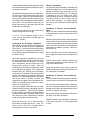
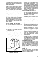
Closet Installation of the Furnace
Return air systems for a closet installation of the
furnace may consist of a grille or grilles in a
closet door or side wall that
communicates with the living area of the home.
(See Figure 6) Return air openings should not
be located to draw air directly from a bathroom.
Grilles placed in a side wall require a 6" clearance from the wall to the furnace so that the air
may enter the front grille of the furnace. In
addition, all return air systems, including the
floor and ceiling systems, must meet the following conditions:
E. Materials located in the return duct system
shall have a flame spread classification of
200 or less.
F. Noncombustible pans having one inch
upturned flanges are located beneath
openings in a floor return duct system.
G. Hollow spaces used as ducts or plenums
for environmental air may contain mineralinsulated metal sheathed cable, aluminum
sheathed cable, electrical metallic tubing,
rigid metal conduit, flexible metal conduit
not to exceed four (4) feet, or metal-clad
cables. Wiring materials, fixtures, are to
be suitable for the expected ambient
temperatures to which they will be subjected.
H. Gas piping cannot be located in the return
duct system.
I. The negative pressure in the closet must
not be less than minus 0.05 inches water
column with the closet door closed and the
fan operating at high speed. A reading
below minus 0.05" indicates a dirty filter or
a restricted return air system.
A. The return-air opening into the closet,
regardless of its location, is to be a minimum of 200 square inches.
B. If the return-air opening is located in the
floor of the closet (versus the vertical front
or side wall), the opening is to be provided
with means to prevent its inadvertent closure by a flat object placed over the opening.
C. The cross-sectional area of the return
duct system (when located in the floor or
ceiling of the manufactured home) leading
into the closet is to be not less than 200
square inches.
D. The total free area of the openings in the
floor or the ceiling registers serving the
return air duct system is to be not less than
300 square inches. At least one such
register is to be located where the likelihood of its being covered by carpeting,
boxes, and other objects is minimized.
Figure 6. Closet Installation
8
J. For floor return systems, the manufactured housing manufacturer or installer
shall affix a prominent marking on or near
the appliance where it is easily read when
the closet door is open. The marking shall
read: “CAUTION, HAZARD OF ASPHYXIATION. DO NOT COVER OR
RESTRICT FLOOR RETURN AIR OPENING.” or equivalent. (This label is supplied
with the instruction manual in each furnace.)
the front tolerance is not less than 4".
Adjust duct registers to obtain a temperature rise within the range specified on the
furnace nameplate.
! WARNING:
Failure to comply with the above procedure and the following instructions may
result in fire, asphyxiation or carbon
monoxide poisoning.
K. For closet installation with less than 6"
front clearance, but not less than 1", a
louvered door must be used having a
minimum 200 square inch free area opening directly in line with openings in the
furnace door. A fully louvered door having
the minimum free area is also permitted if
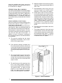
SRJ Roof Jack Installation
Refer to Figure 7 to determine SRJ roof jack
and appropriate accessories required for
your installation.
RA-S4
4/12
49" to 59"
14" Removable SRJ3, SRJ4, & SRJ5
25" Removable All -C Models
RA-S3
SRJ5
3/12
37" to 48"
RA-S2.5
2-1/2
SRJ4
/12
Adaptor
None
25" to 36"
SRJ3
Flat
13" to 24"
12" or Less
When roof pitch is:
Use Adaptor
Model No.
SRJ2
SRJ1
Ceiling Trim Plates
1/2 Minimum
OPTIONAL:
Raised Inlet Models (-C)
RoofJack Adaptor (Use to mount roofjack on pitched roof)
Protective Cap (Use when top of roofjack is removed)
When Ceiling Cavity is:
Use Roof Jack Model No.
Furnace
CMF Series
57"
SRJ1 & SRJ2 Models are one piece construction
SRJ3, SRJ4, & SRJ5 Models are two piece construction
-C Models are two piece construction
And Ceiling Height is:
Add Suffix
For Vent Pipe
7'
-28
7'6"
-34
8'
-40
Add -C for Raised Inlet Models
Example: SRJ3-34-C
Furnace Base Package for O.E.M. and replacement installations . Model No. MA-200
See Replacement Parts List for types of Base Packages offered.
Furnace Base Package for replacement installations ..................... Model No. MA-100
See Replacement Parts List for types of Base Packages offered.
Figure 7. Selection of Roof Jack and Accessories Chart
9
! WARNING:
1. The roof jack and vent pipe as determined from the chart on in Figure 7
must be applied.
2. The indicating line near the bottom of
the roof jack must extend below the
finished ceiling.
3. The vent pipe must be attached to the
furnace flue collar with the sheet metal
screw provided.
4. DO NOT install any elbows (adjustable or non-adjustable) or a stack
damper in the venting system.
NOTICE: Accuracy in locating the base pan
and the roof jack openings with respect to the
flue outlet is required to avoid hazardous misalignment of the air and vent systems. (See
Figure 1)
Use only the SRJ series roof jack as specified
on the furnace label.
Cut an approximate 8-1/4" diameter opening
through the roof and ceiling directly in line with
the flue connection on the top of the furnace.
;;;;
;;;;
;;;;
;;;
;;;
Roof
Ceiling
Fasten Ceiling
Trim Plates
Insert Sliding Pipe
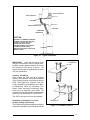
Ease the roof jack assembly through the openings. The lower portion of the outer barrel must
extend through the finished ceiling as indicated
on the barrel. Use sealant or caulking on the
roof or adaptor to seal under the flashing of the
roof jack assembly.
Extend the vent pipe down to engage the locking
slot with the screw in the top of the furnace flue
pipe. Turn to lock and tighten the screw. All
joints and connections should be inspected
before start up of the furnace. (See Figures 8
& 9)
Fasten the ceiling trim/fire stop plates around
the upper barrel with four nails or wood screws
(not provided).
SLIDE DOWN TO
ENGAGE SCREW
TURN TO LOCKTIGHTEN SCREW
Fasten adaptor to
sloped roof; apply
sealant or caulking
underneath
;;;
;;;
;;;
;;;
FLUE PIPE
OF FURNACE
VENT PIPE
Roof Jack Adaptor
Install With Line
Below Ceiling
Figure 8. Roof Jack
10
Insert the vent pipe into the bottom of the roof
jack; locking slot, downward, toward the furnace. Slide the pipe into the roof jack to a length
that will allow a convenient reach to the connection at the top of the furnace.
NOTE: Model SRJ-3, 4, and 5 roof jacks
permit the top section to be removed for transit
of the dwelling. If the top is removed, remaining
openings must be sealed from rain, debris, etc.,
until the top is replaced. A plastic accessory
cap is to be fastened to the lower roof jack
section with the same screws used to mount the
roof jack cap assembly. (See Figure 8)
Fasten roof flashing to adaptor
or flat roof; apply sealant or
caulking underneath
Remove three screws
to separate two piece
models; replace with
protective cap for
transit only
A roof jack adaptor is required for use on a
sloping roof. Center the adaptor opening over
the roof opening, use sealant or caulking under
the adaptor. Use roofing nails or screws on
wood construction or sheet metal screws on
metal roofs (caulking, nails or screws not provided).
Figure 9. Vent Pipe Installation
3 FEET MIN.
ROOF JACK ASSY.
ROOF CAP ASSY.
DRAW BAND
FLEX DUCT
CEILING TRIM COLLAR
VENT PIPE
DRAW BAND
CONNECTOR
CAUTION
MAINTAIN 2 1/2" MINIMUM CLEARANCE
BETWEEN FLUE PIPE AND FLEX DUCT.
FAILURE TO COMPLY WITH THIS
RESTRICTION COULD CAUSE
EQUIPMENT DAMAGE. VENTILAIRE III
ILLUSTRATED OTHER LISTED
VARIATIONS AVAILABLE. CHECK WITH
MANUFACTURER.
FURNACE FURNACE
Figure 10. Typical Installation
IMPORTANT: When the top section of the
roof jack is removed for transit, a special warning label must be attached adjacent to the fuel
line connection of the gas or oil burner. The
special warning label is suppled with two piece
roof jack assemblies.
VentilAire III
Chimney Installation
When venting the CMF through an existing
chimney, the materials, sizing, and installation
of the chimney must be in accordance with the
ANSI Z223.1/NFPA 54, (National Fuel Gas
Code), ANSI/NFPA 31(Installation of Oil Burning Equipment), NFPA 211 (Chimneys, Fireplaces, Vents, and Solid Fuel-Burning Appliances) and all applicable local codes. The
materials used must be capable of withstanding
exposure to temperatures of at least 700°F .
The CMF power gas units are fan-assisted.
Installation of Ventilaire III or IV Air
Quality Package (Accessory)
The Ventilaire air quality packages are available
to meet the ventilation requirements as outlined
VentilAire IV
Figure 11. VentilAire III and IV
11
in H.U.D. Standard Part 3280.103 (b) (2). These
packages introduce outdoor air into the living
space during furnace blower operation. The
VentilAire IV also serves to exhaust moist and/
or hot air from the attic space. See Figures 10
and 11 for typical installation. Complete
installation instructions are supplied with each
air quality package.
FUEL CONNECTIONS
Gas Piping Requirements - PG Series Only
Gas piping should be sized and installed in
accordance with local codes ANSI Z223.1/
NFPA 54 (National Fuel Gas Code) and utility
regulations. To install the gas supply piping,
connect a separate gas line from the gas meter
to the burner with a manual shut-off valve
installed in the line at the furnace. This valve
should be readily accessible to shut-off the gas
supply to the furnace in case of an emergency
shutdown. When installing the gas supply line,
always use new clean piping and route the line
in such a manner as to be easily accessible.
The piping and threading must be free from
cutting burrs and defects. The line must be
durable, substantial, and gas tight. Installing a
tee fitting with a sediment trap at the bottom of
the riser to catch any foreign debris in the gas
supply line is recommended. An additional main
manual shut-off valve may be installed in the
gas supply line to shut-off the main fuel supply,
if desired by the homeowner or required by local
codes.
The proper gas supply line size can be
determined using the gas piping chart, shown
in Table 3. Black pipe is the most practical for
natural gas, because of the larger sizes required.
Copper tubing with an internal coating of tin is
recommended for use with propane (LP) gas
installations. Compounds used on the threaded
joints must be resistant to the actions of propane
(LP) gases.
Carefully check for gas leaks with a soap
solution or a commercial leak detector fluid.
NEVER USE A MATCH OR OPEN FLAME TO
DETECT A GAS LEAK!
! CAUTION:
The furnace and its appliance main gas
valve must be disconnected from the gas
supply piping system during any pressure testing of that system at test pressures in excess of ½ psi (3.5 kPa). The
furnace must be isolated from the gas
supply piping system by closing the equipment shut-off valve during any pressure
testing of the gas supply piping system at
test pressures equal to or less than ½ psi
(3.5 kPa).
Oil Piping Installation — PO Series Only
The following procedures are recommended
as good practice. However, requirements of
local codes and ordinances, H.U.D. Manufactured Home and Safety Standards or National
Fire Protection Association must be satisfied,
where they apply, for an approved installation.
Use a tank capacity suitable for the application
with a weatherproof, capped fill opening and a
shielded vent to let in air as fuel is used. The tank
must be clean inside before filling. All water,
rust, sediment, and other foreign matter must
be flushed out.
If a two pipe system is used or if oil is taken from
the bottom of the tank, a filter is recommended.
Furthermore, a manual shut-off valve may be
used on a single pipe or two pipe system. Please
note that local codes will dictate the specific
installation requirements.
Maximum Possible Pipe
Length Required for Different
Pipe Diameters
Type of
Pipe
Black Iron
Pipe for
Natural Gas
1/2"
5/8"
3/4"
1"
20’
_
60’
100’
10’
_
30’
_
_
40’
100’
_
Aluminum or
Copper Tubing*
for Natural Gas
Aluminum or
Copper Tubing
for LP Gas
*Copper tubing should be internally tin coated.
Table 3. Pipe Length Selection Chart
12
A fuel or tank gauge is recommended for easy
checking of the fuel level. Check the gauge
reading with a dip stick.
Locate the storage tank conveniently near the
home. For above ground fuel tank installations,
the tank may rest three to four inches off the
ground. Fuel tanks may also be buried if
properly coated to resist corrosion. For below
ground fuel tank installations, the vertical dimension from the bottom of the tank to the fuel
pump must not exceed ten feet. Keep the tank
filled especially in the summer to reduce the
accumulation of condensation.
Fuel Line Hook-Up: One Line System
The one line system is highly recommended
where vertical lift, from bottom of tank to pump,
is not more than eight feet. A single line hookup
has the advantage of costing less and giving
quieter operation.
Fuel Line Hook-Up: Two Line System
Use a two line system only if the vertical lift
exceeds 8 feet.
1. Install the oil feed line as outlined in steps
1-6 below.
2. Install the oil pump bypass plug in the
bottom return port.
3. Run the return line up through the furnace
base to the return port of the pump. Run
the other end of the line to the tank, using
3/8" O.D. copper tubing or 1/4" pipe with
the ends capped, and routing the line so it
stays clean.
3/8" Oil Supply Line
Gauge
Vent with
Cap
2" Duplex
Bushing
2" Fill
Hook-Up Procedure (See Figure 12)
1. Use 3/8" O.D. copper tubing for the fuel
line. Cap the end with tape to keep out dirt
while the line is being routed.
2. Install duplex bushing for two 3/8" lines in
the top fitting of the tank.
3. Insert one end of the tubing through the
duplex bushing until it is three to five inches
from the bottom drain. Tighten the bushing.
4. Run the line where it will not be subject to
damage. Also make bends gradually and
avoid kinks which might restrict oil flow.
5. Open the burner access door. Connect
the oil line to the intake port on the pump.
Tighten other port plugs on the pump.
6. Be sure the oil line is airtight! Air leaks can
cause the pump to lose prime and will
create other problems such as nozzle
failure, odors, rumbling noise, and false
safety shut down.
7. Insert the short length of the copper tube
level with the bottom of the duplex bushing.
Tighten the bushing. Form the tube into an
inverted “U” to serve as a vent.
How to Eliminate Air Leaks
To eliminate problems caused by air in the oil
line, all connections in the oil supply line and all
plugs, nuts, and fittings on the pump must be
airtight. This includes the nut that covers the
pressure adjustment. It is important that the
hook-up be done carefully and with a good
flaring tool.
Guide pipe
Note: Additional venting may
be required if tank is filled rapidly.
4. Insert the return line through the second
opening in the duplex bushing. If the
bottom of the tank is lower than the pump
intake, the tube should be inserted three or
four inches from the tank bottom. If the
bottom of the tank is higher than the pump
intake, the return line should extend not
more than 8" inside the tank.
Drain
End of Oil Supply Line
3" to 5" Above
Bottom Drain
Figure 12. Recommended Tank Hook-Up
200 to 300 Gallon Tank
Fuel Oil Type
Do not use fuel oil heavier than Grade No. 2.
Grade No. 1 may be used where the oil supply
is subject to low temperatures.
13
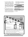
Figure 13. Wiring Diagram
Brn
4
4
Wht
3
3
6
Door
Switch
L1
120V N
G
6
5
2
2
Blue
Blk
5
1
1
Red
1
Blk
Blk
Wht
1
Wht
L1 N
Burner
Plug
Ignition
Transformer
Burner
Motor
Blk
ORANGE
WHITE
BLACK
Burner Plug
Blk
Blk
Fan & Limit
Control
Aux.
Sw.
Door
Sw.
Recpt.
Motor
N
Cad Cell
F
F
Primary T1
Control
T2
7037900
If any of the original wire supplied
with the appliance is replaced, use
105 C wire or equivalent.
Limit
Sw.
Fan Sw.
G
120V
High
Manual Sw.
L1
Black
Med.
Low
Blue
Red
Aux. Limit
Blower Speed Setting Shown
is the Medium Speed
(see table)
Receptacle
Wht
1
1
Blue
Red
Model AF-15 Oil Burner
Represents Control Box
Blower
Motor
Capacitor
Brn
Blower
Motor
Blower
Speed
L2
C
FSG
PSO
GV
FSI
W
PSI
GAS
VALVE
BLUE
GREEN
RED
RED
WHITE
RED
BLACK
BLACK
BLACK
BLACK
BLUE
1/4 IN. QUICK CONNECT TERMINAL
SCREW TERMINAL
1 POWER SUPPLY. PROVIDE DISCONNECT MEANS
AND OVERLOAD PROTECTION AS REQUIRED.
LEGEND:
W
R
Y
G
RC
GROUND
SCREW
BUSHING
CAD
CELL
BURNER
MOTOR
L2
R7184
T
L1
T
CAD
CELL
BLUE
IGNITOR
BURNER
MOTOR
ORANGE
WHITE
LIMIT
BLACK
COOLING
CONTROL
JUNCTION
BOX
FAN RELAY
L2
TERMINAL
BOARD
1
L1
(HOT)
OPTIONAL 24V COMMON
(FOR OPTIONAL ACCESSORY KITS)
C
BURNER ELECTRICAL BOX T T
(C & W)
YELLOW
CLOSED
END
CONNECTOR
BUSHING
TO COMBUSTION MOTOR
IGNITOR
BUSHING
L1
N
BUSHING
T8600
LINE CORD
BLUE
Typical wiring diagram
for 24 Vac thermostat
and R7184 for an
oil-fired forced
air system
CONTROL
MODULE
HSI
HSIG
L1
IND
IGNITOR
TERMINAL HOUSING
Model PGB-DI Power Gas Burner “Direct Ignition”
RED
Blower
Wire
Color
RED
BLACK
Model CMF Series Furnace
BLACK
14
L1
(HOT)
L2
1
DO NOT USE GASOLINE, CRANKCASE OIL,
OR ANY OIL CONTAINING GASOLINE.
! WARNING:
Failure to keep supply oil clean by various
procedures described above may cause
failure of certain components such as the
fuel pump gears, check valve, shaft seal,
or burner nozzle which may result in a
burner fire.
ELECTRICAL WIRING
General
All electrical wiring must be made in accordance
with these instructions, all local codes, and
ANSI/NFPA 70 (National Electric Code). This
furnace shall be installed so the electrical
components are protected from water.
If any of the original wiring supplied with the
appliance must be replaced, it must be replaced
with wiring of the same material, gauge, and
temperature rating.
Line Voltage Requirements
Before proceeding with the electrical connections, make certain that the voltage, frequency,
and phase of the supply source are the same
as those specified on the unit rating plate. This
unit must be electrically grounded in accordance with local codes, or in the absence of
local codes, with ANSI/NFPA 70 (National Electrical Code).
Use 14-2 Type NM cable with ground or conduit
with single wires. Secure the cable at the
appliance using a code approved connector.
Line Voltage Connections
Before connecting the power supply wiring,
become familiar with the wiring of this appliance
by reviewing the wiring diagram, shown in
Figure 13 , or the wiring label located on the
inside of the appliance.
1.
Open the appliance door to gain access to
the control box.
2.
Remove the control box cover.
3.
Connect the black wire of the power supply
cable to the black wire of the appliance.
4.
Connect the white wire of the power supply
cable to the white wire of the appliance.
5.
Connect the ground wire of the power
supply cable to the green screw located in
the control box of the appliance.
6.
Check all electrical connections, which
should be secure and tight.
Scaleplate
50
FA
OF
F
1
00
N
LIM IT
ON
OFF
Limit Stop*
0
Fan OFF
Indicator
250
CAUTION
Do Not Rotate — Hold
Dial When Setting Pointers
20
150
Limit Indicator
(Factory-Set at 160 F)
Fan ON
Indicator
Figure 14. Fan and Limit Settings
15
7.
Replace the control box cover.
8.
Install a disconnect switch (fused or unfused) between the appliance and the
electrical supply at a convenient location
near the appliance. This switch should be
easily accessible.
Room Thermostat Requirements
When selecting thermostat location, consideration must be given to the following:
1.
Locate the thermostat approximately five
feet above the floor in a location accessible
for wiring and setting, preferably in a living
or adjoining room.
2.
Locate on an inside wall.
3.
Do not locate where influenced by abnormal heat, such as from sunlight, radio,
T.V., or lamps.
4.
Do not locate where influenced by abnormal cold, such as on an outside wall, on a
wall separating an unheated room,
near drafts from stairwells or doors, or
close to windows.
5.
Do not locate where air circulation is poor,
such as behind open doors, in corners or
alcoves, or close to furniture.
The heat anticipator of the thermostat should be
adjusted to .4 amps for power oil models, and
.9 for power gas direct ignition models.
or constant blower operation. Pull the button out
for automatic operation. Push the button in for
constant blower operation.
Fan and Limit Settings
! CAUTION:
When adjusting the fan setting levers,
hold the scaleplate dial to keep it from
turning and straining the sensing element.
The fan and limit switch has three levers: FAN
ON, FAN OFF, and LIMIT OFF. These levers
control the blower operation of the appliance.
The FAN ON lever controls the temperature at
which the blower energizes. This lever can be
adjusted through a range of 15oF above the FAN
OFF setting to 30 oF below the LIMIT OFF
setting. The recommended factory setting is
110 oF.
The FAN OFF lever controls the temperature
at which the blower is to stop to prevent the
circulation of cool air. The recommended factory
setting is 90 oF.
The LIMIT OFF lever is a safety stop. This lever
should not be adjusted or tampered with for any
reason. The factory setting is 160 oF.
Room Thermostat Connections
1.
Run R and W from the thermostat to the
burner compartment.
2.
Connect R to one of the low voltage
terminals on the burner.
3.
Connect W to the other low voltage terminal
on the burner.
FAN AND LIMIT CONTROLS
Constant Blower Operation
The button protruding through the cover of the
fan and limit control provides either automatic
operation of the blower through the thermostat
16
Figure 15. Direct Ignition Gas Valve
Auxiliary Limit
This furnace is equipped with an auxiliary manual
reset limit. This limit is designed to function
("trip") in the event of a blower motor failure. If
the limit trips, reset the limit by firmly pressing
the red button in the center of the limit. The limit
is located on the left hand side of the blower
assembly. If the limit will not reset, continues to
trip, or the blower does not function, notify your
NORDYNE Distributor or Service PRO
immediately.
MAINTENANCE
Air Filters
Air filters should be inspected and cleaned
monthly.
Combustion Air and Venting System
Inspect the combustion air and venting system
at the beginning and end of the heating system
for deterioration, blockage, or damage. Clean
the system, if necessary.
LIGHTING AND OPERATING
INSTRUCTIONS FOR CMF PG DIRECT
IGNITION GAS BURNERS
For Your Safety Read Before Lighting or
Operating.
! WARNING:
If you do not follow these instructions
exactly, a fire or explosion may result
causing property damage, personal injury or loss of life.
A. This appliance does not have a pilot. It is
equipped with an ignition device which
automatically lights the burner. Do not try
to light the burner by hand.
B. BEFORE LIGHTING OR OPERATING
smell all around the appliance area for gas.
Be sure to smell next to the floor because
some gas is heavier than air and will settle
on the floor.
WHAT TO DO IF YOU SMELL GAS:
• Do not try to light any appliance.
• Do not touch any electric switch, do not
use the phone.
• Leave the building immediately, then
call your gas supplier.
• If you cannot reach the gas supplier, call
the fire department.
C. Use only your hand to push in and move
the gas control lever. Never use tools. If
the lever will not push in by hand, don't try
to repair it, call a qualified service technician. Force or attempted repair may result
in a fire or explosion.
D. Do not use this appliance if any part has
been under water. Immediately call a
qualified service technician to inspect the
appliance and to replace any part of the
control system and any gas control which
has been under water.
E. Should overheating occur, or the gas supply fail to shut off, turn off the manual gas
valve to the appliance.
Operating Instructions for PG Direct
Ignition Burner
1. STOP! Read the safety information above.
2. Set the thermostat to OFF or to its lowest
setting.
3. Turn off all electric power to the appliance.
4. This appliance is equipped with an ignition
device which automatically lights the
burner. DO NOT try to light the burner by
hand.
5. Turn the latch and open the furnace door.
6. Push in the gas control lever and move to
OFF. DO NOT FORCE.
7. Wait ten (10) minutes to clear out any gas.
If you then smell gas, STOP! Follow
Section B in the safety information above.
If you don’t smell gas, go to the next step.
17
Burner
Designation
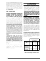
Gas Gun-65-DI-S
Gas Gun-75-DI-S
Gas Gun-90-DI-S
Firing Rate
Input
(BTUH)
65,000
75,000
90,000
Natural Gas
Orifice
Number
24
20
16
Natural Gas
Time Per Rev.*
(sec)
55
48
40
LP Gas
Orifice
Number
43
40
36
LP Gas Time
Per Rev.**
(sec)
138
120
100
* There times are based on natural gas at an average of 1,000 BTU per cubic foot, a burner
manifold pressure of 3.5 in WC, and a meter dial size of 1 cubic foot.
** There times are based on LP gas at an average of 2,500 BTU per cubic foot, a burner
manifold pressure of 3.5 in WC, and a meter dial size of 1 cubic foot.
Table 4. Natural and LP Gas Orifices
8. Move the gas control lever to ON.
1.
Shut off all other gas fired appliances,
except for any pilots.
2.
Start the furnace in heating mode and allow
it to run for at least three minutes.
11. Turn the thermostat to ON and set to the
desired setting.
3.
12. If the appliance will not operate after one
re-try, follow the instructions in the “To
Turn Off Gas To Appliance” Section below
and call your service technician or gas
supplier.
Measure the amount of time (in seconds)
required for the gas meter to complete one
revolution. Note that one revolution will be
equal to one cubic foot of gas.
4.
Compare the time measured with the
appropriate time listed in Table 4. If the time
varies by more that 5% from the times
shown in the table, then measure the inlet
and gas valve manifold pressures, using
the procedure outlined in the “Measuring
the Inlet Supply and Manifold Pressures”
section.
If both the inlet gas pressure and the
manifold pressure are properly set, then
check the burner orifice to ensure that it is
properly sized. Further gas problems
should be referred to the local gas supplier.
9. Close the furnace door and turn the latch.
10. Turn on all electric power to the appliance.
To Turn Off Gas to the Appliance
1. Set the thermostat to OFF or to its lowest
setting.
2. Turn off all electric power to the appliance
if service is to be performed.
3. Turn the latch and open the furnace door.
4. Push in the gas control lever and move to
OFF. DO NOT FORCE.
5.
Checking the Input of the Furnace
Refer to the rating plate on the furnace to
determine the firing rate for your application.
Using Table 4, determine the appropriate orifice
size for the firing rate and gas being used in your
application. Check the burner orifice to ensure
that it is the correct size.
Measuring the Inlet Gas and Manifold
Pressures
For natural gas installations, the inlet gas line
pressure at the gas valve inlet must be between
5 in WC and 7 in WC. For LP gas installations,
the incoming gas line pressure at the gas valve
inlet must be between 11 in WC and 13 in WC.
This pressure can be checked at the port
located on the gas inlet end of the gas valve
using a pressure gauge or U-tube manometer,
which must be installed according to the
manufacturer’s supplied instructions.
The input of this furnace can be checked using
the following procedure, which is based on
using a one cubic foot gas meter:
For natural gas installations, the manifold
pressure must be set at 3.5 in WC. For LP gas
installations, the manifold pressure must be set
5. Close the furnace door and turn the latch.
18
5.
Regulator
Converter
After measuring the pressure, be sure to
remove the pressure gauge or U-tube
manometer from the gas valve and replace
the tap plug. Ensure that the tap plug is tight
and not cross-threaded.
Gas Burner Controls
The gas valve lever can be set to ON or OFF,
as shown in Figure 16. When in the ON position,
gas flow through the gas valve is allowed when
the valve is energized electrically. When in the
OFF position, gas flow is completely shut off.
Combustion Blower Centrifugal Switch
Figure 16. Natural Gas Configuration
at 10.0 in WC. This pressure can be checked
at the port located on the gas outlet end of the
gas valve using a pressure gauge or U-tube
manometer, which must be installed according
to the manufacturer’s supplied instructions. If
the manifold pressure is not equal to the valves
above, then it must be adjusted. To adjust the
manifold pressure, remove the regulator
converter from the gas valve, as shown in
Figure 16. Then turn the adjusting screw
clockwise to increase the pressure or
counterclockwise to reduce the pressure. Once
the manifold pressure is correctly set, replace
the regulator converter in the same manner as
it was removed earlier.
To install a pressure gauge or U-tube manometer
in the gas valve:
1.
Determine which pressure, the inlet gas or
manifold pressure, you want to measure.
2.
With a 3/16” Allen wrench, remove the
appropriate tap plug located on the gas
valve. When measuring the inlet gas
pressure, remove the tap plug on the inlet
side of the gas valve. When measuring the
manifold pressure, remove the tap plug on
the outlet side of the gas valve.
3.
4.
Install a fitting, which has a 1/8” NPT pipe
thread that is compatible with the pressure
gauge or U-tube manometer.
Install the pressure gauge or U-tube manometer according to the manufacturer’s
supplied instructions.
Input
(BTU/H)
65,000
75,000
90,000
Natural
Gas Setting
3.0
3.5
4.0
LP Gas
Setting
3.0
3.5
4.0
Oil
Setting
3.0
4.0
3.5
Table 5. Air Shutter Setting
for Different Fuels
The electric motor for the blower which supplies
combustion air to the burner is equipped with a
centrifugal switch wired in series with the burner
controls. This switch is normally open until the
speed of the blower motor closes it thereby
powering the burner controls. The burner
controls will not function until the blower motor
is operating at full speed.
Natural Gas to LP Conversion
This gas fired heating appliance was shipped
from the factory for use with natural gas. However, the appliance can be converted to be used
with LP gas. Use the following procedure for
gas conversion of the burner.
1. Follow instructions “To Turn Off Gas To
Appliance” earlier in these instructions.
2. Shut off gas supply at meter.
3. Disconnect gas burner electric cord, gas
piping to burner, and thermostat leads.
4. Remove three (3) hexagon nuts holding
burner in place.
5. Disconnect inlet pipe union at burner.
19
6. Disconnect the two wires leading to gas
control valve.
7. Remove three (3) bolts from U-shaped
manifold plate and orifice assembly.
8. Remove the main orifice and replace it with
the appropriate LP fuel orifice. Refer to the
rating plate on the furnace to determine the
firing rate for your application. If the firing
rate of your furnace has been converted,
ensure that the appropriate LP orifice for
the new firing rate is installed. Then, use
Table 4 to determine the proper LP orifice
for your firing rate.
9. Remove the regulator converter and its
black cover located on top of the gas valve
and invert. (See Figure 16 — For LP, the
red ring will be located at the bottom and the
“LP” stamping on the converter will appear
right side up.)
10. Screw converter back into the regulator,
hand tight plus
1/8 turn, and replace the black cover onto
the converter top to protect the threads.
11. Reinstall the burner assembly into the
furnace.
13. Open the manual shut-off valve and follow
the “Operating Instructions” as outlined
previously in this manual to put the furnace
into operation.
Adjusting the Burner
The air shutter is factory pre-set for installation
in a given furnace, as shown in Table 5. You
should not need to adjust the air shutter setting
of the gas gun burner except when converting
the firing rate of the furnace. For your installation,
check to ensure that the air shutter setting is
correct. It is very important that the combustion
air supply be ample without decreasing the
efficiency of the burner. An inadequate amount
of air can cause carbon monoxide (CO)
production. The carbon dioxide (CO2) content
of the flue products should be in the range of
8.0% to 9.0% for natural gas and 9.0% to 10.0%
for LP gas. The burner should run quietly.
For high altitude operation (altitudes greater
than 2,000 feet), the input should be de-rated by
4% for each 1,000 feet above sea level by
reducing the orifice size or decreasing the
manifold pressure. When decreasing the
manifold pressure, the pressure must not be
set below 3.2 in WC. If the pressure needs to
be set below 3.2 in WC to achieve the proper derate, then change the orifice size and raise the
manifold pressure back to 3.5 in WC.
12. Reconnect the gas piping and electrical
wires to the gas valve.
AIR BLEED
VALVE
NOZZLE
PORT
5/32" Gap
Electrode
5/16" ABOVE CL
1/16"
INLET PORT
NOZZLE
PORT
WEBSTER
INLET PORT
Nozzle
1-1/8" - 65,000 and 75,000
BTU/HR Inputs, FO Head
1-13/32" - 90,000 BTU/HR
Input, F3H Head
AIR BLEED
VALVE
INLET PORT
SUNTEC
Figure 17. Oil Pumps
20
Figure 18. PO Oil Burner Electrode Settings
(Time to bleed air out will vary depending
on length of oil line, number of bends, etc.)
LIGHTING AND OPERATING INSTRUCTIONS FOR CMF PO OIL BURNERS
Oil burners in this series are factory equipped
with a primary control capable of either
intermittent or interrupted ignition.
Start-Up Procedure
1.
Open all manual shut-off valves in the oil
supply line from the tank to the burner.
7.
Remove the jumper wire on the primary
control.
Oil Burner Shutdown Procedure
Set the room thermostat to “OFF” or its
lowest setting.
Flame Adjustment
2.
Turn ON the electrical supply to the
furnace.
1.
Turn the thermostat to a setting below
room temperature to start the furnace.
3.
Set the room thermostat to the desired
temperature.
2.
Allow the furnace to operate for about ten
(10) minutes.
3.
Adjust the air shutter setting until 11% CO2
with a number zero smoke or less is
achieved. Furthermore, the draft over the
fire must be at least negative 0.02 in WC.
The factory set air shutter settings are
shown in Table 5.
Air-Bleed Procedure - Single Pipe
Installation
1.
Open the door to the furnace.
2.
Attach 1/4" I.D. plastic tube over the end
of the airbleed valve on the oil pump as
shown in Figure 17. Place the other end
of the tube in a large container.
3.
Pull the door interlock switch out to start
the burner.
4.
Turn the airbleed valve open not more than
1/2 turn to get a fast flow of oil into the
container.
5.
To assure continuous operation, use a
wire to jump terminals T-T (or F-F) on the
primary control while burner is running. If
furnace is equipped with the Honeywell
R7184 primary control, priming oil pump
procedure is as follows:
a.
While the ignition is on, press the
reset button for 1/2 second or less
and release the reset button. The
lockout time will be extended to 4
minutes.
b.
If prime is not established within the
4 minutes, the control will lock out.
Press the reset button to reset the
control and to step “a”.
c.
6.
Repeat steps “a” and “b”, if needed,
until the pump is fully primed.
When oil flow is clear and free of air
bubbles, close air-bleed valve and tighten.
Electrode Setting
The electrode setting is carefully set at the
factory. However, during transit, the setting of
the electrodes may become improper. Before
attempting to start the oil burner, check the
positioning of the electrodes to ensure that they
are properly positioned, as shown in Figure 18.
Improperly adjusted electrodes can result in
poor ignition. Do not permit the electrodes to be
closer than ¼” to any grounded surface.
SWITCHING FROM INTERRUPTED TO
INTERMITTENT IGNITION CONTROL
Honeywell oil primary control can be switched
between interrupted and intermittent ignition
control. To switch from interrupted duty (Factory
set) to intermittent duty, remove the ignitor wire
from the blue control wire. Attach the burner
motor and igniter wire to the orange control wire.
Cap and reseal the orange wire. Cap and isolate
the blue control wire. Refer to Figure 13.
FIRING RATE CONVERSION
The rated firing rates of the CMF80 convertible
furnaces (PO & PG) can be adjusted from the
factory setting of 75,000 BTU/hr. The firing rate
can be changed to either 65,000 BTU/hr or to
90,000 BTU/hr using the appropriate certified
NORDYNE conversion kit installed by a
NORDYNE distributor or Service PRO. See the
Replacement Parts Listing for the appropriate
kit number to order.
21
FURNACE OPERATING SEQUENCE
A. Gas Furnace
1. On a call for heat, the thermostat contacts
close, which applies 24 volts to the “W”
terminal.
2. The combustion blower motor energizes.
After the motor begins to rotate, the
centrifugal switch, which is located in the
motor end cap, closes.
3. A thirty (30) second pre-purge period
begins, during which the ignition control will
initiate an internal safety start check.
4. Upon passing the safety check, the control
begins a fifteen (15) second ignitor warmup period. During this period, the ignitor will
warm to the ignition temperature.
can be reset by interrupting the 24 volt power.
This can be easily accomplished by setting the
thermostat below room temperature for at least
forty five (45) seconds, and then returning it to
the desired setting.
If adjusting the thermostat does not reset the
ignition control, turn off the power to the appliance
for forty five (45) seconds, and then turn it back
on.
NOTE: If the gas control has been replaced or
serviced, lighting may not be satisfactory until
air has been purged from the gas line or the gas
input and combustion air have been adjusted.
B. Oil Furnace - Honeywell R7184 Control
1.
When a call for heat is initiated, there is a
2-6 second delay while the control
performs a safe start check.
5. The control then applies 24 volts to the gas
valve.
2.
6. The ignitor ignites the gas, and the
presence of flame will be detected using
flame rectification principles.
The ignition and motor are turned on and
a flame should be established within the
15-second lockout time.
3.
If flame is not sensed within the 15-second
lockout time, the control shuts down on
safety lockout and must be manually reset.
If control locks out three times in a row, the
control enters restricted lockout. To reset,
hold down the reset button for 30 seconds
until the LED flashes twice.
4.
Once flame is established, the ignition
remains on 10 seconds to ensure flame
stability. It then turns off. (interrupted
ignition)
8. The circulating air blower will energize
thereafter, when the temperature fan
switch closes.
5.
The circulating air blower will energize
thereafter, the temperature fan switch
closes.
9. When the thermostat is satisfied, the “W”
terminal is de-energized.
6.
The furnace runs until the call for heat is
satisfied. Burner is shut down.
10. The gas valve circuit will be de-energized,
and the gas valve will close.
7.
The circulating air blower will de-energize,
when the temperature fan switch opens.
11. The circulating air blower will de-energize,
when the temperature fan switch opens.
ADJUSTING HEAT DISTRIBUTION
7. The flame must be detected within a timed
trial ignition period. If the flame is detected,
then the ignitor is de-energized. The gas
valve will remain open until the call for heat
from the thermostat is completed.
Conversely, if the flame is not detected,
then the control will close the gas valve at
the end of the timed trial ignition period. The
control will then attempt ignition two (2)
more times before locking out.
The control will close the gas valve, if the
presence of flame is not or no longer detected.
The control will attempt to re-ignite the gas twice
before locking out. Once in lock-out, the control
22
1. Set the room thermostat for the desired
room temperature.
2. Balance the heat distribution by adjusting
the register openings.
SERVICE GUIDE FOR FURNACES WITH
PGB POWER BURNER WITH DIRECT
IGNITION
! CAUTION:
Verify proper operation after servicing.
! IMPORTANT:
1. Always disconnect power before servicing.
2. Only persons trained and experienced
in direct ignition systems should service this equipment.
3. If a condition exists that causes the
ignition control to go into safety
lockout, meter readings must be
taken quickly after restart - within trial
for ignition period.
4. Always de-energize the system for at
least 45
seconds before recycling for further tests.
5. The ignition control cannot be repaired.
If the troubleshooting procedure
indicates a malfunction in the control, it must be replaced.
! CAUTION:
Label all wires prior to disconnection
when servicing controls. Wiring Errors
can cause improper and dangerous operation.
A. Burner motor does not run - thermostat
calls for heat.
1. Defective thermostat circuit - bridge
TT connections on burner junction
box, if burner motor runs, check:
a. Thermostat connections
b. Thermostat
2. No voltage to burner - plug test lamp
into burner plug receptacle, if it does
not light, check for:
a. Blown fuse, electric supply off
b. Door switch not making contact
c. Limit switch in open mode
d. Check for clean air filter and proper
airflow
e. Loose wire connections
f. Check for tripped manual reset auxiliary limit.
3. 120 volts is available to burner - Test
lamp does not light. Remove junction
box cover on burner, check for:
a. Loose wires
b. Defective transformer
c. Defective motor
B. Burner motor does not run, no main flame.
1. Defective centrifugal switch
a. Check the operation of centrifugal
switch by removing end bell of the
burner motor.
2. Check for gas supply - gas line valve
on, control lever on.
3. Check for burner safety lockout. (Restart burner)
4. Check for 24 volts to ignition control
a. No voltage at purge timer - check
the centrifugal switch in the combustion motor.
b. No voltage to ignition control - check
purge timer (allow one minute for
purge timer to activate).
c. Check for 120 volts to ignition control. (-Voltmeter at L1 and L2).
C. Ignition control is powered (120v and 24v).
Ignitor does not heat up.
1. Remove AMP plug from burner tube
receptacle and check for 120 volts at
the plug during ignition sequence
2. Replace ignition control if 120 volts is
not supplied to AMP plug within 3 minutes of ignition cycle start.
D. 120 volts is available at AMP plug. Ignitor
does not heat up.
1. Disconnect burner plug from furnace
receptacle.
2. Disconnect AMP plug from burner tube
receptacle and check ignitor circuit
through receptacle with an ohmmeter.
23
a. Normal ohm reading should be between 40 to 75 ohms.
b. An infinite or zero ohm reading indicates a defective ignitor and it must
be replaced.
3. Check for continuity from ignitor receptacle to burner ground.
4. Check for hairline cracks in ignitor’s
insulating ceramic.
5. Check thermostat anticipator. (0.9
amps)
H. Burner does not shut off. (Note: Burner
will stop when the door switch is open. With
the door open, secure the door switch in
the closed position by depressing the
switch. The means for securing the door
switch must be removed once this testing
has been completed.
1. Disconnect the thermostat wires from
TT connections on the burner junction
box. If the burner shuts off, check for:
! WARNING:
When replacing the ignition control, replacement control MUST have the safety
lockout time. FAILURE TO FOLLOW
THIS WARNING MAY RESULT IN AN EXPLOSION.
E. Main flame ignites but burner locks out.
1. Ignition control is not properly
grounded.
2. Defective ignition control.
3. Improper gas pressure or burner air
adjustment is not allowing flame to
contact ignitor tip for flame proving
rectification.
F. 24 volts supplied to gas valve during ignition but no main gas flow.
1. Gas valve may be defective. Replace
if necessary.
2. Gas piping may be plugged. Check for
adequate gas supply to gas valve at
union.
G. Burner operates, insufficient heat
1. Check the thermostat for proper setting and location. The thermostat
should not be located where it will be
affected by another heat source.
(Lamps, ovens, sunlight, etc.)
b. Defective thermostat.
I.
Burner flame without motor running — gas
valve is stuck in open position — Replace
the control, burner and heat exchanger
may need cleaning.
J. Noisy fire — Readjust combustion air to
reduce volume of air being drawn into the
burner. (Caution — See “Adjusting the
Burner” or “Flame Adjustment” sections)
K. High Gas Bills
1. Check the combustion air adjustment.
2. Be sure the proper size orifice is being
used.
3. Be sure the return air filter is clean.
4. Be sure the home is insulated, windows and doors fit tightly, and there
are no air leaks in the heating ducts.
5. Check room thermostat to be sure the
setting is not higher than necessary.
Low humidity requires higher temperatures for comfort. Perhaps humidity
should be increased.
L. Circulation blower will not operate even
though the burner operates.
2. Check for clean air filters and proper
air flow.
1. Turn on the manual blower switch, if
the blower operates, check the fan
switch.
3. Check burner for proper gas firing
rate.
2. Check the wiring to the motor.
4. Be sure unit is not undersized for its
thermal load.
24
a. Short circuit in the thermostat wires.
3. Check for a burned out motor.
Control Module Status Indicator
A. Gas Furnace
1. One flash - the control is in lock-out
because the inducer centrifugal switch
is or was stuck closed.
2. Two flashes - the control is in lockout
because the signal was not received
by the control that the inducer
centrifugal switch had closed within
the time.
3. Three flashes - the control is in lockout
because a failed ignition attempt, a gas
valve error, or a false flame sensed
during the warm up period. A false
flame condition exists when the flame
sensor senses a flame without a flame
present. If a false flame has been
sensed, the control will only return to
normal operation after the false flame
condition is no longer present.
A. Burner does not start with a call for heat.
1. Check the electrical supply to the
furnace.
2. Be sure the furnace door switch is in
the on position.
3. Check for line voltage at the oil primary
control. The
voltage should be 115 VAC.
4. Check indicator light with burner off, no
call for heat (no
flame).
a. If indicator light is on, the cad cell
is seeing stray light or the cad cell
or controller is defective.
b. If Indicator light is off, go to step 5.
c. If flashing, reset as B 1.
4. Four flashes - the control is in lockout
due to a failure within the control board.
5. Jumper T to T terminals on primary
control.
B. Oil Furnace
The indicator light on the oil primary control
provides lockout,
recycle, and cad cell indications as follows:
a. If burner starts, check thermostat
or limit wiring
connections.
1. Flashing ½ second on, ½ second off system is locked out or in restricted
mode.
2. Flashing 2 seconds on, 2 seconds off
- control is in recycle mode.
3. Indicator light is on - cad cell is sensing
flame.
4. Indicator light is off - cad cell is not
sensing flame.
TROUBLESHOOTING- Honeywell R7184
Primary Control
The following service procedures will help you
become familiar with the R7184 oil primary
control. For further service information, please
refer to Honeywell R7184 Installation Instructions, 69-1233 and Beckett Technician's Quick
Reference Guide, RWB 61351.
b. If burner does not start, turn off
power. Check all
wiring connections.
c. If burner does not start, replace
R7184 control.
B. Burner starts, then locks out on safety
with indicator light flashing at ½
second on, ½ second off.
1. Reset primary control.
To reset the control from lockout, the
button needs only to be pressed and
released. If it is in restricted mode, the
button should be held in for 30
seconds (until the light flashes twice,
or until the light stops flashing on
earlier models).
Note: Restricted Mode: If the control
locks out three times in a row without
a complete heat cycle between
attempts, the lockout becomes
restricted mode.
25
a. If indicator light stops flashing and
ignition remains off, primary control could be defective. If line
voltage is present at the ignitor
terminals, but there is no ignition,
the ignitor is probably defective and
needs to be replaced.
b. If indicator light stops flashing, burner
turns on, but control locks out again,
check cad cell. If cad cell is Okay,
replace primary control.
c. If Indicator light continues to flash at
½ second on. ½ second off, verify
that control is not in restricted mode,
if restricted mode, reset it. If not in
restricted mode, replace R7184.
d. If indicator light stays off while the
flame is on, check cad cell sighting
for view of flame.
e. If burner locks out, check cad cell
resistance.
Led Flashes
1
2
3
4
f. If burner keeps running, system is
Okay.
g. If indicator light is off, check cad
cell assembly after disconnecting
line voltage power.
C. Burner will not start, and indicator
light is flashing at 2 second on, 2
second off.
Hold the reset button down for 1-2
seconds. If indicator light continues to
flash, wait for 60-70 seconds. If it still
continues to flash, replace the primary
control.
D. To Check Cad Cell Resistance.
Press and release the button during the
run mode. The light will flash to indicate the
cad cell resistance. For proper burner
operation, it is important that the cad cell
resistance reading is not over 1600 Ohms.
For cad cell resistance, see Table 6.
Cad Cell Resistance in Ohms
0 - 400
400 - 800
800 - 1,600
>1600
Table 6. Cad Cell Resistance when sensing flame
26
INSTALLER: Please leave
these installation instructions
with the homeowner.
EFFICIENCY
R AT I N G
C E RT I F I E D
ama
¢708062¬¤
708062
708062B (Replaces 708062A)
O’Fallon, MO
Specifications and illustrations subject to change
without notice and without incurring obligations.
Printed in U.S.A. (8/03)