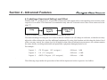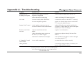
1
AM-777 Premier Class
Pre-Main Amplifier
Owner’s Manual
Ver 1.7.5
FCC Declaration of Conformity - United States only
the receiver is connected.
This device complies with Part 15 of the FCC rules. Operation is subject
to the following two conditions: (1) This device may not cause harmful
interference, and (2) this device must accept any interference received,
including interference that may cause undesired operation.
- Consult the dealer or an experienced radio/TV technician for help.
FCC WARNING:
This Class B digital apparatus meets all requirements of the Canadian
Interference-Causing Equipment Regulations.
Changes or modifications to this unit not expressly approved by the party
responsible for compliance could void the user's authority to operate the
equipment.
Canadian Notice (Avis Canadien)
Class B Equipment
Cet appareil numérique de la classe B respecte toutes les exigences du
Règlement sur le matériel brouilleur du Canada.
NOTE:
This equipment has been tested and found to comply with the limits for a
Class B digital device, pursuant to Part 15 of the FCC Rules. These
limits are designed to provide reasonable protection against harmful
interference in a residential installation. This equipment generates, uses,
and can radiate radio frequency energy and, if not installed and used in
accordance with the instructions, may cause harmful interference to radio
communications. However, there is no guarantee that interference will
not occur in a particular installation. If this equipment does cause harmful
interference to radio or television reception, which can be determined by
turning the equipment off and on, the user is encouraged to try to correct
the interference by one or more of the following measures:
- Reorient or relocate the receiving antenna.
- Increase the separation between the equipment and receiver.
- Connect the equipment into an outlet on a circuit different from that to
which
2
This products complies with the EMC Directive (89/336/EEC) and the
Low Voltage Directive (73/23/EEC) issued by the Commission of the
European Community.
Compliance with these directives implies conformity to the following
European Norms (in parentheses are the equivalent international
standards and regulations):
o EN55022 (CISPR 22) - Electromagnetic Interference
o EN55024 (IEC61000-4-2, 3, 4, 5, 6, 8, 11) - Electromagnetic Immunity
o EN61000-3-2 (IEC61000-3-2) - Power Line Harmonics
o EN61000-3-3 (IEC61000-3-3) - Power Line Flicker
o EN60950 (IEC60950) - Product Safety
WARNINGS
The exclamation point within an equilateral triangle is intended to alert
the user to the presence of important operating and maintenance
(servicing) instructions in the literature accompanying this component.
!
This component weighs over 15 kilograms. Do not place this component on an unstable cart, stand, tripod, bracket or table as the component may fall causing serious injury to a child or adult and serious
damage to the unit. An appliance and cart combination should be
moved with care. Quick stops, excessive force and uneven surfaces
may cause the component and cart combination to overturn.
Any mounting of the device on a wall or ceiling should follow the Manufacturer ’s instructions and should use a mounting accessory
recommended by the manufacturer.
Read and follow all the safety and operating instructions before
connecting or using this component.
All warnings on the component and in its operating instructions should
be adhered to.
Retain this Owner’s Manual for future reference.
Do not use this unit near water; for example, near a bath tub, washbowl,
kitchen sink, laundry tub, in a wet basement or near a swimming pool.
Unplug the component from the wall outlet before cleaning. Never use
benzine, thinner or other solvents for cleaning; use only a soft damp
cloth.
Care should be taken so that objects do not fall, and liquids are not
spilled into the enclosure through any openings.
This component should be serviced only by qualified AMR service
personnel when:
A.
The power cable or the power input socket has been damaged;
B.
Objects have fallen, or liquid has been spilled into the component;
C.
The component has been exposed to rain or liquids of any kind;
D.
The component does not appear to operate normally or exhibits a
marked change in performance;
E.
The component has been dropped or the enclosure has been damaged.
DO NOT ATTEMPT SERVICING OF THIS UNIT YOURSELF. REFER
SERVICING TO QUALIFIED AMR SERVICE PERSONNEL
Upon completion of any servicing or repairs, request the service point’s
assurance that only AMR Authorised Replacement Parts with the same
characteristics as the original parts have been used, and that the routine
safety checks have been performed to guarantee that the
component is in a safe operating condition.
REPLACEMENT WITH UNAUTHORIZED PARTS MAY RESULT IN
FIRE, ELECTRIC SHOCK OR OTHER HAZARDS
3
Precautions
On placement
This equipment has been tested and found to comply with the limits
set out in the EMC Directive using a connection cable shorter than 3
metres.
The AM-777 may become warm during normal operation. Given this, it
is imperative that the AM-777 when installed, its location or position
DOES NOT interfere with its proper ventilation.
On power sources
For example, it should not be situated on a bed, sofa, rug or similar
surface that may block the top or bottom ventilation openings; or placed
in a built-in installation, such as a bookcase or cabinet, that may impede the flow of air through its top and bottom ventilation openings.
The mains power cable should be routed so that it is not likely to be
walked on or pinched, especially near the plug or back panel receptacle.
The component should not be disconnected from the AC power source
as long as it is connected to the wall outlet, even if the component itself
has been turned off.
If this component is not going to be used for a long time, be sure to
disconnect the component from the wall outlet. To disconnect the AC
power cable, grasp the plug itself; never pull the cable.
CAUTION
RISK OF ELECTRIC SHOCK
DO NOT OPEN
!
Do not place the component in a location near heat sources, or in a
place subject to direct sunlight, excessive dust, or mechanical shock.
Do not place the component in an inclined position.
It is designed to be operated in a horizontal position only. Do not place
heavy objects on the component.
Keep the component away from equipment with strong magnets, such
as microwave ovens or large loudspeakers.
To prevent fire or shock hazard, do not place vessels filled with liquids,
such as vases, on the component.
Running-In
AMR estimates that the AM-777 may take between 300-500 operating
hours for all of the internal components to be fully-broken in. Please
anticipate the sonic performance of the AM-777 to settle only after it has
been used for this approximate length of time.
4
Contents
WARNINGS
3
Section 1 - Unpacking and Setup
1.1 Unpacking
1.2 Setup
7
8
Section 2 - Component Overview
2.1 Front Panel
2.2 Rear Panel
2.3 Remote Control
9
10
12
Section 3 - Operation
3.1 Power On/Off
3.2 Volume Adjustment
3.3 Rear Inputs
3.4 USB Input
3.5 Mode switch
3.6 Pre-Main/Power switch
3.7 HiFi/Pro switch
3.8 Preamplifier Output connector
13
13
13
13
14
14
14
14
5
3.9 Speaker Impedance
3.10 Mains Voltage switch
14
15
Section 4 - Advanced Features
6
4.1 Labelling of Inputs and Setting Level Offset
4.2 Labelling Input X
4.3 Setting Level Offset
4.4 Setting Fixed Input Level for Bypass Mode
4.5 OptiProtect® Speaker Overload Protection
17
19
19
20
22
Appendix A - Troubleshooting
23
Section 1 - Unpacking and Setup
Thank you for purchasing this AMR Premier Class component.
We hope you derive as much pleasure from using this component as we have enjoyed making it for you.
1.1 Unpacking
This section refers to the unpacking of the AM-777 and its subsequent setup.
Upon unpacking, please find:
Please check that all
contents are present
i.
AM-777 Premier Class Dual-Mono Pre-Main Amplifier.
ii.
RCD-777 Remote Commander.
iii.
Mains power cable.
iv.
AM-777 Owner’s Manual.
v.
AMR Warranty Card.
vi.
AMR System Test Disk.
Please ensure that all items are present. Should an item be missing, please contact your AMR distributor/dealer.
7
1.2 Setup
Pre-Main Stereo Amplifier Connection (8 Ohm Speakers)
Default Pre-Main
mode: the AM-777 as
an integrated amplifier
The following diagram illustrates the standard connection of the AM-777 in pre-main stereo amplifier mode. This is
the default factory setting and is suitable for the majority of audio systems.
Speaker R
Speaker L
HF
HF
LF
LF
Speaker Cable
!
Speaker Cable
M M
No User Serviceable Components Inside.
For service , contact your Authorised
Dealer or Distributor . Any modifications to
this equipment will void all warranties .
Power
On
Pre - Main Amplifier AM - 777
Great Britain
Inputs
2
1
3
CLASS 1
LASER PRODUCT
Speaker
Outputs
Pre
Out
4
Off
~ AC
L
R
L R
CAUTION ATTENTION
L
RISK OF ELECTRIC SHOCK
DO NOT OPEN
USB
Input
M M
RISQUE DE CHOC ELECTRIQUE
NE PAS OUVRIR
M
4R
L R
R
L
R
Warning: ensure
no speaker connector is in contact
with the chassis to
cause a shortcircuit!
M
!
Input 1
SERIAL NO.
IR
Link
Interconnect Cable
Power
On
No User Serviceable Components Inside.
For service , contact your Authorised
Dealer or Distributor . Any modifications to
this equipment will void all warranties .
Compact Disk Processor CD - 777
Outputs
Great Britain
Digital
USB
Input
Input
Output
R
!
CLASS 1
LASER PRODUCT
~ AC
Off
Outputs
IR
Link
CAUTION ATTENTION
RISK OF ELECTRIC SHOCK
DO NOT OPEN
RISQUE DE CHOC ELECTRIQUE
NE PAS OUVRIR
SERIAL NO.
CD - 777
8
8R
AM - 777
Interconnect Cable
4R
L
8R
Section 2 - Component Overview
2.1 AM-777 Front Panel
The plastic protective film covering
the display may be
removed
F1
F2
F3
F1. STANDBY: to place the AM-777 in active or standby mode.
F2. SOURCE: to select between the different inputs.
F3. VOLUME: to adjust the volume level.
9
2.2 AM-777 Rear Panel
!
Warning: ensure that the
correct mains
voltage and
speaker
impedance are
selected!
R2
R3
R6
10
R9
R7
R5
R1
R4
R8
R11
R10
R13
R12
R1. SPADE/BANANA outputs: for connection of standard termination speaker cables.
R2. USB input: for direct connection to a Computer Audio Source.
R3. HIFI/PRO switch: to allow for a source with a transformer balanced output.
R4. POWER switch: to switch on/off mains electricity to the AM-777.
R5. 115V/230V: to switch to the correct local mains voltage.
R6. INPUT 1: shared XLR and RCA input.
R7. INPUTS 2-4: RCA inputs.
R8. IEC power connector: for the connection of a mains power cable to the AM-777.
R9. PREAMPLIFIER Output: to connect a separate pre-amplifier.
R10. MODE switch: to alternate between Stereo/Monoblock/Bi-Amplification settings.
R11. PRE-MAIN/POWER amplifier switch: to select Pre-Main or Power Amplification setting.
R12. 4R/8R speaker: to select the correct speaker impedance for speakers used.
R13. Infra-Red Link: for connection of a wireline remote control.
In the majority of audio systems, the AM-777 is most likely to be operated as a Pre-Main Amplifier. Please inspect
the rear panel of the AM-777 to verify that the default settings (in bold) are as follows:
- HIFI/PRO switch (R3) is set to HiFi (set to lower position)
- MODE switch (R10) is set to LR (set to middle position)
- PRE-MAIN/POWER switch (R11) is set to Pre-Main (set to lower position)
- 4R/8R switch (R12) is set to 8R (unless speakers with 4R or lower impedance are used)
11
2.3 RCD-777 Remote Control
RC1. MENU: to enter Advanced Features mode*.
RC2. STANDBY: to place the AM-777 in active or standby mode.
RC3. SOURCE: to select between the 5 different inputs.
RC4. VOLUME: to adjust the volume level.
RC5. MUTE: to mute (temporarily turn off sound) the AM-777.
RC6. BRIGHTNESS: to adjust brightness levels.
RC7. OK: to be used in Advanced Features mode*.
RC7
RC1
* Please refer to Section 4 - Advanced Features for more details.
RC6
RC2
RC5
RC3
12
RC4
Section 3 - Operation
3.1 Power On/Off
Once powered OFF:
always wait 30
seconds before
switching on again
Press the ‘POWER’ rocker switch (R4) at the rear of the AM-777 to switch on mains power . To switch the mains
power OFF, press again and release. Always wait at least 30 seconds before switching ON again. This is to
enable the AM-777 circuits to shutdown properly.
3.2 Volume Adjustment
Adjust the volume up or down to attain a comfortable level for listening.
3.3 Rear Inputs
Beware: prolonged
listening at high
volume levels is
likely to damage your
hearing
At the rear of the AM-777, there are 4 sets of RCA inputs for the connection of source components such as the
CD-777 compact disk processor or a vinyl source. The XLR input is shared with the RCA Input 1. The fifth input
is USB only and can only be selected if connected to a Computer Audio Source.
If the AM-777 is used in single-channel mode, all other inputs are defeated. Signal input is allowed only through the
LEFT channel (white) of Input 1: via XLR or RCA.
3.4 USB Input
The AM-777 can be connected via a USB connection (R2) directly to a Computer Audio Source for sound playback. No software drivers are required under Windows XP SP2 or later and Mac OS X. Make sure the playback
application is set correctly to output sound to the ‘USB Audio Device’.
13
3.5 Mode switch
At the rear of the AM-777 the “Mode” switch (R10) allows the AM-777 to alternate between Stereo/Monoblock/
Bi-Amplifier modes.
3.6 Pre-Main/Power switch
At the rear of the AM-777, the “Pre-Main/Power” switch (R11) enables the AM-777 to alternate between PreMain or Power amplification modes.
3.7 HiFi/Pro switch
At the rear of the AM-777, the “HiFi/Pro” switch (R3) allows for a source with a transformer balanced output to be
connected to the AM-777.
3.8 Preamplifier Output connector
At the rear of the AM-777, the preamplifier output (R9) allows the AM-777 to drive other amplifiers (including AM777 switched to power amplifier mode) or subwoofers. The output level of the preamplifier output varies with
volume changes on the AM-777.
3.9 Speaker Impedance switch
At the rear of the AM-777, the 4R/8R speaker impedance switch (R12) allows the AM-777 to be configured to
correctly match the impedance of the speakers used.
14
3.10 Mains Voltage switch
At the rear of the AM-777, the 115V/230V switch (R5) allows the AM-777 to be configured to correctly match the
local mains voltage.
Warning: setting this switch incorrectly may damage your AM-777!
15
This page has been intentionally left blank
16
Section 4 - Advanced Features
4.1 Labelling of Inputs and Setting Level Offset
With the AM-777, in one process, it is possible to label each of the inputs with a corresponding source and to set the
respective level offset. This function is recommended only after ALL desired sources have been connected to the
AM-777.
Setup
Labeling
Input X
Setting Level
Offset
A list of available labels is shown overleaf in chronological order.
The main advantage of setting the level offset is that the volume level will change in real-time, so that the user may
adjust the offset without the need for additional equipment. By using this function and selecting the desired level
offset, one may ‘match’ the volume level of all inputs so that when switching between sources, the volume remains
the same, thereby avoiding undesirable and potentially equipment-damaging noise levels.
For example:
Input 1
CD Player (2V output)
Offset: 0dB
Input 2
LP (1V output)
Offset: +6dB
Input 3
SACD Player (4V output)
Offset: -6dB
.
The following steps outline the procedure to label all the inputs and set the respective level offset.
17
List of available inputs:
All types of sources
accomodated
1. Input X (default)
15. PC Audio
2. Aux I
16. Phono Stage
3. Aux II
17. Plasma TV
4. Aux III
18. Pre-Amplifier
5. CD Processor
19. SACD Player
6. D/A Processor
20. Tape Deck
7. DVD Player
21. Television
8. DVD Recorder
22. Tuner
9. HD Recorder
23. Turntable
10.HDTV
24. Uni Player
11.iPod
25. Video Player
12.LCD TV
26. Home Theatre
13.Media Center
27. Home Theatre Direct
14.MP3 Player
18
4.2 Labelling Input X
• Press the Menu key on the RCD-777
• Use the Volume+/Volume- to scroll through the labels (see previous page for the full list of available labels)
• Press the OK key on the remote to store the new name
You will then move automatically onto ‘Setting Level Offset’
4.3 Setting Level Offset
• Level Offset is flashing on the 1st line of the display
• Use the Volume+/Volume- to increase/decrease the offset, the volume will also change in realtime
• The range of offset available is from -18dB to +12dB
• Press the OK key on the remote to store the desired offset
Repeat this for all the inputs.
19
4.4 Setting Fixed Input Level for Bypass Mode
When using the AM-777 as part of a home theatre system with an external processor controlling the overall system
volume, it is possible to program one of the five input sources to have a fixed level of input such as for a home
theatre system of either 0.775V (0dbu) or 1.55V (+6dBu). This allows the 2-Channel music system to be seamlessly integrated into a high-performance multi-channel home cinema system.
- Go to Section 4.1 and follow the instructions to select the last label:
HTD mode: always
use an external
pre-amp as this
mode will switch
the AM-77 to full
volume!
H
o
m
e
D
i
T
h
e
a
r
e
c
t
t
r
e
• Simultaneously press ‘+’ volume (F3) on the front panel of the AM-777 and ‘OK’ (RC7) on the RCD-77
• Press the Volume+ button untill the display reads +12dB, press Volume+ again
• Press the OK button to enter the (Volume Control) Bypass mode
• Confirm the warning message by pressing Volume+ or press OK to exit without enabling Bypass mode
• Then select one of the following settings using Volume+/Volume - :
20
Fixed Input 2V = +6dBu
or
Fixed Input 1V = +3dBu
or
Fixed Input 0.5V = +0dBu
• Press OK on the remote to store the new fixed input Level
Warning! By selecting Home Theater Direct mode, the volume of the amplifier will be switched to full.
Hence if it is used incorrectly, it will damage the connecting speakers. AMR assumes no responsibility
for any speaker damage arising from use of the AM-777.
21
4.5 OptiProtect® Speaker Overload Protection
Within OptiProtect® the AM-777 has an in-built speaker protection circuit.
This is primarily a safeguard against equipment failure and/or extreme levels of over-driving the amplifier and
speakers.
When the display shows:
S
p
e
a
k
e
r
E
n
g
P
r
o
t
e
a
g
e
d
!
c
t
i
o
n
This indicates the AM-777 has detected an output condition that could potentially damage the speakers connected
to it.
Normally, switching the AM-777 off, waiting 30 seconds and switching it back on will reset the protection circuit if
the cause was for example, excessive signal levels. In the extremely rare event that an internal malfunction of the
AM-777 is the cause for the protection circuit to engage, the protection will re-engage on switch-on, indicating the
need for the AM-777 to be serviced at an AMR service centre.
22
Appendix A - Troubleshooting
Symptom
Possible Cause
Solution
With power ON
at mains power point
• poor/no power plug connection
no power is registered
• insert the power plug firmly into the AC
• blown fuse at IEC/mains plug
• check and change IEC/mains plug fuse
• incorrect audio cable connections
• connect the sources to the AM-777 correctly
• incorrect amplifier operation
• make sure that the input selector on the AM777 is set to the desired source
Strange “blast” sound
• check speaker connectors are not
in contact with the chassis and terminal
• adjust fitting between speaker and chassis
• Ensure no contact between chassis and spade
terminals (no “short circuiting”)
Remote control does
not work
• remote control batteries have
expired
• replace 2 x AAA batteries
• object obscuring remote sensor on
the AM-777, no “line of sight”
• remove any objects directly in front of the
AM-777
• Interference from fluorescent lights
• turn off fluorescent lights or redirect the light
away from the AM-777
• loose cable connections
• re-attach the loose cables correctly
No sound
A “humming” sound
can be heard
Other problems
• re-trace the setup procedure or contact your
nearest AMR distributor/dealer
Abbingdon Music Research is a subsidiary of the Abbingdon Global Group
22 Notting Hill Gate; London; W11 3JE; United Kingdom;
Tel: +44 (0) 870 420 5505; Fax: +44 (0) 700 596 1065
www.amr-audio.co.uk
23