1
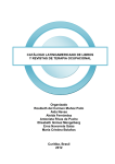
TSC 4036B
1 x 15 RF Distribution
Amplifier
Operations and Maintenance
Manual
Revision E
November, 2010
Contact Information
www.symmetricom.com
[email protected]
Phone:
Worldwide (Main Number) 1-408-428-7907
USA toll-free 1-888-367-7966 (1-888-FOR-SYMM)
2
4036B Operations and Maintenance Manual Rev. E
TSC 4036B 1 x 15 RF Distribution Amplifier Operations and Maintenance Manual
Copyright © 2003, 2010 Symmetricom
Symmetricom is a trademark of the Symmetricom, Inc.
Other product and company names may be trademarks of their respective owners.
DOC04036 Rev E
Revision History
Revision
Description
Date
Approved
A
Initial Release
12/23/03
GAR
B
Added CE information
1/13/04
GAR
C
Added RF gain setting
information
1/29/04
GAR
D
Changed pollution note and
wording for AC disconnect
2/11/04
GAR
11/10/10
GAR
Added requirement for
double shielded BNC cables
Added call out for rear panel
Gnd Stud
E
Revised warranty, shipping
and Declaration of
Conformity information
Changed power input
specifications in Table 3
Changed relative humidity
specifications in Table 4
4036B Operations and Maintenance Manual Rev. E
3
Table of Contents
1: Introduction............................................................................................................................................... 5
1.1 Symbols............................................................................................................................................... 5
1.2 About This Manual ............................................................................................................................. 7
1.2.1 Conventions ................................................................................................................................. 7
1.3 4036B Overview ................................................................................................................................. 8
2: Installing and Setting Up the 4036B ....................................................................................................... 10
2.1 Safety First!....................................................................................................................................... 10
2.2 Unpacking ......................................................................................................................................... 10
2.3 Cleaning ............................................................................................................................................ 11
2.4 Installing the 4036B .......................................................................................................................... 11
2.4.1 Required materials for installation ............................................................................................. 11
2.4.2 Making Connections .................................................................................................................. 11
2.5 Assigning a Static IP Address ........................................................................................................... 12
2.6 Setting the gain ................................................................................................................................. 13
3: Monitoring the 4036B............................................................................................................................. 14
3.1 Accessing the System ....................................................................................................................... 14
3.2 Checking System Status .................................................................................................................... 14
3.2.1 Checking Alarms and Input Frequency...................................................................................... 14
3.2.2 Checking Model Number and Software Version ....................................................................... 15
3.3 Understanding Alarm Output ............................................................................................................ 15
4: Troubleshooting the 4036B .................................................................................................................... 16
4.1 Replacing Fuses ................................................................................................................................ 16
4.2 Verifying Operational Problems ....................................................................................................... 16
5: Shipping Information .............................................................................................................................. 18
5.1 Warranty Information ....................................................................................................................... 18
5.2 Shipping Information ........................................................................................................................ 18
5.2.1 Packing Instructions ................................................................................................................... 18
6: Declaration of Conformity ...................................................................................................................... 20
Appendix A: Specifications ........................................................................................................................ 22
A.1 Electrical Specifications ................................................................................................................... 22
A.2 Environment Specifications ............................................................................................................. 24
A.3 Physical Specifications .................................................................................................................... 24
Glossary ...................................................................................................................................................... 25
Index ........................................................................................................................................................... 26
4
4036B Operations and Maintenance Manual Rev. E
1: Introduction
Note
FIRST READ THIS MANUAL THROUGHLY!
This is especially true for the sections regarding Safety and Installation.
1.1 Symbols
These symbols appear throughout the manual as well as on the unit itself.
Note
This symbol means the following information is a note that gives you
important information that may affect how you use the 4036B.
!
Caution, refer to manual. Read all instructions in Manual
before using this product.
CE marking, attesting compliance to applicable European
Directives
Caution – Risk of Electrical shock
Fuse symbol
Mains Power is ON
Mains Power is OFF
4036B Operations and Maintenance Manual Rev. E
5
LAN port, NETWORK, DO NOT CONNECT TO
TELECOM CONNECTIONS THAT CARRY HAZARDOUS
VOLTAGES.
101010
Serial port connection, DO NOT CONNECT TO
TELECOM CONNECTIONS THAT CARRY
HAZARDOUS VOLTAGES.
Earth terminal symbol: Used to indicate an earth ground
connection to chassis.
6
4036B Operations and Maintenance Manual Rev. E
1.2 About This Manual
This manual tells you how to install, set up, monitor, and troubleshoot the 4036B.
“Chapter 1, Introduction” on page 5 explains symbols that appear in the manual and on the unit as
well as documentation conventions. The chapter also briefly describes the 4036B.
“Chapter 2, Installing and Setting Up the 4036B” on page 10 contains important safety
information and describes how to install the 4036B, and assign a fixed IP address.
“Chapter 3, Monitoring the 4036B” on page 14 describes how to monitor alarms.
“Chapter 4, Troubleshooting the 4036B” on page 16 describes how to replace fuses and verify
operational problems.
“Chapter 5, Warranty and Shipping Information” on page 18 explains how to contact
Symmetricom for warranty service and provides shipping guidelines.
“Chapter 6, Declaration of Conformity” on page 20 provides the information pertaining to CE
marking of this product.
“Appendix A, Specifications” on page 22 contains the detailed specifications for the 4036B.
1.2.1 Conventions
This manual uses several typographical conventions to help explain how to use the 4036B.
Convention
Definition
Bold
Words in bold show:
Buttons and icons to click
Menu options to select
Commands to type
Non-variable information displayed in response to commands
Italics
Words in italics show:
Names of windows and dialog boxes
Variable information displayed in response to commands
4036B Operations and Maintenance Manual Rev. E
7
1.3 4036B Overview
The TSC 4036B is a one input, fifteen output RF amplifier housed in a 1U (1.75”) high 19 inch rack mount chassis.
It provides fifteen outputs from a single input. An Ethernet port on the rear panel provides the capability to remotely
monitor the status of the input and all output signals. Any input or output failure in the unit will immediately provide
an alarm to this port. The front panel provides green LED status for the input and green/red for all output signals, as
well as indicating an input of 1 MHz, 5 MHz, or 10 MHz. A green LED on the front panel also provides power
status.
Figure 1 shows the 4036B’s front panel, and Figure 2 shows the 4036B’s rear panel.
POWER–
Green when
power is on.
INPUT FREQUENCY–
Lit LED shows whether
input is 1, 5, or 10 MHz.
OUTPUT STATUS–
Green during normal operation of output signal.
Red when output signal fails.
Figure 1: Front panel
Additional
Ground
connection
POWER– ETHERNET PORT–
connector
. 1 RJ-45 connector
.
INPUT–
1 BNC connector
.
SIGNAL OUTPUTS–
15 BNC connectors.
Figure 2: Rear panel
8
4036B Operations and Maintenance Manual Rev. E
This page intentionally left blank
4036B Operations and Maintenance Manual Rev. E
9
2: Installing and Setting Up the 4036B
2.1 Safety First!
!
Warnings:
This unit is for INDOOR USE ONLY. It is not protected against a harmful ingress of moisture.
Do not attempt to install or operate this equipment if you have not first acquired proper training.
Equipment is intended to be installed in an Enclosed or Open type equipment rack
Ensure that all cables are properly connected. The power cord must be easy to remove from the
back.
Verify that input line voltage and current capacity are within specifications before turning on
power to the unit.
Disconnect all sources of input power before removing the top cover of this unit.
Operating and maintenance personnel must receive proper training before installing or
maintaining electrical equipment.
2.2 Unpacking
To unpack the TSC 4036B unit:
1. Unpack and carefully inspect the unit.
2. Check for physical damage.
3. If no physical damage is apparent, then proceed with making appropriate connections.
If physical damage is observed, then immediately contact Symmetricom and the
carrier.
4. Save the shipping container for submitting any necessary claims to the carrier.
10
4036B Operations and Maintenance Manual Rev. E
2.3 Cleaning
!
Warning
Do not spray or use too much liquid when cleaning the unit. Liquid can enter the unit and damage
sensitive electronic components.
Clean the main chassis with a soft cloth dampened with a mild soap and water solution.
2.4 Installing the 4036B
The 4036B is shipped ready for installation into a standard 19" (48.3 cm) rack. Provisions are
included for mounting General Devices slides with part numbers C-300-S-126, -128 and -130.
2.4.1 Required materials for installation
North American or European IEC power cord. One or the other will be supplied with the unit.
Customer supplied double shielded RG223 cables with BNC connectors from source, and to
next devices in system.
Customer supplied shielded LAN cable for network connection (RJ-45).
Rack-mount slide kit from General Devices, C-300-S-126, -128 or -130 (Optional)
Rack mounting screws.
Screwdriver for the rack mount screws, and slide as needed.
2.4.2 Making Connections
2.4.2.1 Input Power
AC INPUT POWER - The input power to the unit is supplied through a detachable 3-prong
power cable. First plug the female end into the male IEC-320 plug on the rear of the unit,
then plug the male end of the cable into a 100V~ to 240V~, 50/60 Hz power source.
!
Warning
!
Since the unit does not have a AC Mains Power Switch, both the Appliance Inlet Connector
and the Plug on the detachable type power supply cord are considered to be suitable
Disconnect Means for disconnecting the unit from the AC Mains Supply. If the rear of the
unit is not accessible after installation in the instrument rack, the User is responsible for the
provision of a suitable external AC Disconnect Means for the unit.
Ensure that this power supply cord is connected to a properly grounded mains receptacle to
ensure safety.
2.4.2.2 Input Signal
Connect the input signal cable to the INPUT BNC connector on the back of the unit.
4036B Operations and Maintenance Manual Rev. E
11
2.4.2.3 Output Signals
Connect up to fifteen cables to the OUTPUT BNC connectors on the rear panel of the unit to
supply users with a copy of the input signal.
2.4.2.4 LAN - Ethernet Network Port
Connect a network LAN shielded cable (not supplied with the unit) to the LAN port on
the back of the unit.
2.5 Assigning a Static IP Address
The 4036B contains a Lantronix® Xport™ Ethernet to RS-232 converter, which provides the
4036B’s Ethernet connection.
The 4036B ships from the factory with a default IP address of 0.0.0.0, which enables DHCP. If
the network has a DHCP server, it will automatically assign the unit an IP address, gateway
address, and subnet mask when the unit starts up.
To monitor multiple 4036Bs remotely through their Ethernet connections without DHCP reassigning IP addresses, you must assign each unit a static IP address. You identify which unit is
the source of an alarm by its IP address. Each unit has its own unique hardware address, labeled
MAC address, on a label on the rear panel. Follow the instructions in this section to manually
assign a unit’s static IP address.
Note
For more detailed information, see the Xport™ User Manual. Section 3.3 discusses several
different ways that you can assign IP addresses. Chapter 4 explains how to configure a static IP
address. You can download the Xport™ User Manual from the Lantronix® Web site as an
Adobe® Acrobat® PDF file. Go to:
http://www.lantronix.com/products/eds/xport/XPort_UM_900-270.pdf
If you want to configure a static IP address of many different 4036Bs, you can install the
Lantronix® DeviceInstaller software. This software is available only by downloading from the
Lantronix® Web site. Go to: http://www.lantronix.com/support/utils/dst/index.html. Alternatively
you may use your companies IT protocol to determine the IP address assigned to a particular
hardware address, then set a static address.
To manually assign the static IP address using the Lantronix® DeviceInstaller software:
1. Obtain the following network information from your system administrator for each
4036B you want to install:
IP Address:
______ ______ ______ ______
Subnet Mask: ______ ______ ______ ______
Gateway:
______ ______ ______ ______
2. Connect a Windows® PC to the same local subnet as the 4036B.
3. Install and start the Lantronix® DeviceInstaller software.
4. Click the Search Network icon and search for XPORT devices connected to the
network, press save and then exit.
12
4036B Operations and Maintenance Manual Rev. E
5. Click the IP icon or select Assign IP Address on the Tools menu.
The hardware device number and IP address appear in the Assign IP Address dialog
box.
5. Type the new IP address for the appropriate “Hardware or Ethernet address” and click
Set IP address.
The new IP address appears in the Lantronix® DeviceInstaller window.
6. Test the IP address by pinging the 4036B’s Xport™ on the Lantronix Xport Installer
window. Click the Ping icon or select Ping Device on the Tools menu.
The Ping Device window should show the IP address of the 4036B’s Xport™ device,
and it should show successful replies if the IP address has been configured correctly.
7. Exit the browser.
To change the IP address using telnet:
1. Telnet to the assigned address, port 9999. Press enter within five seconds to enter the
setup mode.
2. Select Option 0
3. Set the IP address and follow on screen commands to save the setting
Sending an I command will turn on the three front panel input LEDs for 2 seconds before
returning to normal operation. This provides the capability for the user to ensure they are
communicating over the Ethernet connection to the correct device via front panel feedback.
Note
If you move the 4036B to a different network hub after setting up the static IP address, the host
computer may not be able to make a connection. You may need to release the IP address lease on
your operating system.
2.6 Setting the gain
!
When opening the top cover and changing the gain settings, proper ESD precautions must be
used. This includes ensuring that you are properly grounded before touching the internal PWA of
the unit to change the jumper settings.
The input/output gain is set to 1 (0 dB) at the factory. The gain can be changed to -1, +1, or +2 dB
by changing the internal jumper settings. To change these settings, remove the top cover and set
the jumpers according to the silk screen shown on the PWA.
4036B Operations and Maintenance Manual Rev. E
13
3: Monitoring the 4036B
3.1 Accessing the System
You access the 4036B system remotely by connecting to its Command-And-Response (CNR)
Port through the Ethernet connection. The CNR port (Port 10001), which uses TCP/IP, lets users
input commands, displays results of the commands, and publishes alarms as they occur.
When users Telnet to the CNR port, the system does not display a prompt.
3.2 Checking System Status
3.2.1 Checking Alarms and Input Frequency
The system can report current alarms, latched alarms, and the type of input signal.
To check system status:
Type: S (case sensitive)
You do not need to type a carriage return or line feed.
The system returns Scccc,llll,x\r\n where
cccc is current alarms.
llll is latched alarms since the last status request.
Both cccc and llll are hexadecimal numbers, with each binary bit position representing
one output. The MSB is the input signal status. The LSB (farthest right) is output 1 status.
A value of 1 in a bit position indicates an alarm condition.
x is one of the values for inputs shown in Table 2.
Table 2: Input values
Value
Input Frequency
0
Not 1, 5 or 10 MHz
1
1 MHz
2
5 MHz
3
10 MHz
Example: S0000,0001,2
14
4036B Operations and Maintenance Manual Rev. E
This example shows that the system has no current alarms, output 1 alarmed since last status
request, and the input frequency is 5 MHz. With no input signal, all output status bits will report
0.
3.2.2 Checking Model Number and Software Version
Both commands are case sensitive. You do not need to type a carriage return or line feed.
To check the TSC model number:
Type: I
The system returns I4036B-00\r\n.
To check the software version
Type: V
The system returns Vxx\r\n where xx is the software version.
Example: V80.
Sending an I command will turn on the three front panel input LEDs for 2 seconds before
returning to normal operation. This provides the capability for the user to ensure they are
communicating over the Ethernet connection to the correct device via front panel feedback.
3.3 Understanding Alarm Output
The 4036B automatically publishes alarms to the CNR port as they occur.
The alarms appear in the format ALARMcccc where cccc is the summary status of the input and
output signals. The format of the alarm status is identical to the “S” command response for
current status.
Example: ALARM0008
This example shows that output 4 failed.
4036B Operations and Maintenance Manual Rev. E
15
4: Troubleshooting the 4036B
Perform all of the following procedures before returning the unit for service. If the unit still
appears to have a problem, then call Symmetricom, Inc and request technical support. Have the
serial number of your unit ready to provide to a technical representative.
4.1 Replacing Fuses
If you know that a local event caused blown fuses throughout a rack, you can replace the fuses in
each 4036B power entry module.
Required for this procedure:
Small flat-head screwdriver
Replacement fuse for a standard IEC 320 power entry module with fuse (5 x 20 mm, 1 A
250 V Time lag fuse)
To replace a fuse:
1. Disconnect the power cable from the back of the 4036B.
2. Using a small screwdriver, open the fuse cover on the back of the 4036B.
3. Replace the old fuses as necessary.
4. Close the fuse cover.
5. Reconnect the power cable to the back of the 4036B.
4.2 Verifying Operational Problems
If the unit does not operate properly after you have verified that:
the correct power is applied to the rear of the 4036B
and
the fuses are good,
call Symmetricom, Inc to obtain a Returned Materials Authorization and return the unit to TSC
for repair.
16
4036B Operations and Maintenance Manual Rev. E
This page intentionally left blank
4036B Operations and Maintenance Manual Rev. E
17
5: Shipping Information
This chapter provides information on how to contact Symmetricom for warranty service, as well
as shipping guidelines for the 4036B.
5.1 Warranty Information
The product carries a warranty from Symmetricom for a period of 1 year from date of shipment.
For repairs, contact Symmetricom:
www.symmetricom.com
[email protected]
Phone:
Worldwide (Main Number) 1-408-428-7907
USA toll-free 1-888-367-7966 (1-888-FOR-SYMM)
5.2 Shipping Information
If you need to ship this system for any reason, including returning equipment to Symmetricom for
warranty service, follow these shipping instructions. Failure to follow these instructions may
damage your system.
5.2.1 Packing Instructions
18
Always ship the 4036B appropriately packaged to protect it from damage, preferably in
the package in which it was originally shipped.
No cables or connectors may be attached to the rear of the chassis.
Wrap the chassis in plastic to protect against moisture.
4036B Operations and Maintenance Manual Rev. E
This page intentionally left blank
4036B Operations and Maintenance Manual Rev. E
19
6: Declaration of Conformity
Declaration of Conformity
In accordance with ISO/IEC GUIDE 22 and EN 45014
Symmetricom, Inc.
4775 Walnut St., Suite 1 B
Boulder, CO 80301-2574
Declares under our sole legal responsibility that the
DISTRIBUTION AMPLIFIER
MODEL NO. TSC 4032B
MODEL NO. TSC 4033A
MODEL NO. TSC 4036B
MODEL NO. TSC 4059B
MODEL NO. TSC 4130A
CONFORMS TO THE FOLLOWING EUROPEAN UNION DIRECTIVES:
Safety
2006/95/EC Low Voltage Directive (LVD)
IEC 61010-1:2001
EN 61010-1:2001
Electromagnetic Compatibility
2004/108/EC Electromagnetic Compatibility (EMC) Directive
EN61326 (2006) EMC Requirements for Measurement, Control and Laboratory
Equipment, Class B
EN61000-3-2 (2006) Harmonic Current Emissions
EN61000-3-3 (1995) w/A1:2001, A2:2006 Voltage Fluctuation and Flicker Emissions
WEEE
Waste Electrical and Electronic Equipment Directive (WEEE) 2002/95/EC
20
4036B Operations and Maintenance Manual Rev. E
For more information about Symmetricom’s WEEE compliance and recycle program, please visit the
Symmetricom’s WEEE/RoHS website at
http://www.symmetricom.com/About_Us/WEEE_RoHS_Initiatives.htm
RoHS
Restriction of the Use of Certain Hazardous Substances Directive 2002/95/EC
This product falls under the category of Monitoring and Control Instruments Equipment
(Category 9 as defined in Annex 1A of the WEEE 2002/96/EC Directive) which is excluded from
the RoHS Directive 2002/95/EC (reference Article 2, paragraph 1) requirements.
We declare that the equipment specified above conforms to the above Directives and Standards.
03 November 2010Robert MengelbergCompliance Engineer Robert Mengelberg
Date
NameTitleSignature
4036B Operations and Maintenance Manual Rev. E
21
Appendix A: Specifications
A.1 Electrical Specifications
Table 3 lists the electrical specifications for the 4036B.
Table 3: Electrical specifications
Item
Specification
Protection Class
Class I (Grounded Type)
Power Input Voltage
90 – 264 VAC 47 – 63Hz, 0.5 A
Note: Fluctuations not to exceed ± 10% of nominal supply voltage.
Caution: The above AC Power Supply specification reflects the
overall Power Supply ratings. For UL and CE compliance the
Power Supply must only be operated at 100 – 240 VAC, 50-60 Hz.
Power Inlet Type
IEC 60320 sheet C14
Power Supply Cord Set
18 AWG (0.75 mm2 minimum)
Power Mains Fuse
(2) - 250V~1A Time lag 5x20 mm
Signal Input and output
Frequency 1 – 20 MHz
Impedance: 50 Ω ± 5 Ω
Input level 0- 1 V rms (13 dBm)
Connectors
Input: 1 BNC
Output: 15 BNC
LAN: RJ-45
Gain
Factory setting is 1.0 ± 10%, can be changed via internal jumper settings to -1,
+1 or +2 dB
Isolation
> 100dB (with 5 MHz signal)
Spurious distortion
< - 80 dBc (with 5 MHz signal)
Harmonic distortion
< - 40 dBc (with 5 MHz signal)
22
4036B Operations and Maintenance Manual Rev. E
Item
Specification
SSB phase noise
1 Hz
-135 dBc
10 Hz
-145 dBc
100 Hz -155 dBc
1 kHz
-163 dBc
10 kHz -163 dBc
4036B Operations and Maintenance Manual Rev. E
23
A.2 Environment Specifications
!
Warning
Ordinary protection: This unit is for INDOOR USE ONLY. It is not protected against a harmful
ingress of moisture.
Equipment intended to be installed in an Enclosed/Open type equipment rack
Pollution Degree 2 per EN61010-1
Installation (Over-Voltage) Category II for transient over-voltages per EN 61010-1
Equipment suitable for continuous operation
Table 4 lists the environmental specifications for the 4036B.
Table 4: Environment specifications
Item
Temperature
Relative Humidity
Altitude
In Use
0°C to 50°C
0% to 95%
(non-condensing)
3,000 meters
(9,843 feet)
Storage
-40°C to 70°C
0% to 95%
(non-condensing)
Transportation
-40°C to 70°C
0% to 95%
(non-condensing)
A.3 Physical Specifications
Table 5 lists the physical specifications for the 4036B.
Table 5: Physical specifications
Item
Specification
Width
Standard 19-inch rack mount
Height
Standard 1U (~1.75 inches or 4.44 cm)
Depth
31.875 cm or 12.75 inches
Weight
Approximately 4.1 kg
24
4036B Operations and Maintenance Manual Rev. E
Glossary
\n
Line feed
\r
Carriage return
CNR
Command and Response
DHCP
Dynamic Host Configuration Protocol
ESD
electrostatic discharge
LED
light-emitting diode
LSB
least significant bit
MSB
most significant bit
PDF
portable document format
PWA
printed wiring assembly
RF
radio frequency
4036B Operations and Maintenance Manual Rev. E
25
Index
4036B
accessing, 14
alarms, 15
command interface, 14
front panel, 8
installing, 11
monitoring, 14
rear panel, 8
specifications, 22
unpacking, 10
accessing
4036B system, 14
alarms
checking, 14
understanding, 15
assigning
gateway address, 12
IP address, 12
subnet mask, 12
CE marking
symbol, 5
checking
alarms, 14
input frequency, 14
model number, 15
software version, 15
system status, 14
Command-And-Response Port
explained, 14
commands
system, 14
connections
Ethernet, 8
input power, 8, 11
input signal, 8
output signal, 8
conventions, typographic, 7
DeviceInstaller
software, 12, 13
Ethernet
connecting, 14
port, 8, 12, 14
fuse
replacing, 16
symbol, 5
gateway address
assigning, 12
information
26
shipping, 18
warranty, 18, 20
input
connector, 8
LEDs, 8
input frequency
checking, 14
input plug
symbol, 5
input power
connecting, 11
installing
a 4036B, 11
instructions
packing, 18
safety, 10
IP address
assigning, 12
LAN port
symbol, 5
Lantronix®
DeviceInstaller software, 12, 13
Lantronix® Xport™. See Xport™., 12
LEDs
input, 8
output, 8
power, 8
model number
checking, 15
monitoring
a 4036B, 14
operational problems
verifying, 16
output
connectors, 8
LEDs, 8
packing
instructions, 18
panels
front, 8
rear, 8
ports
Command-And-Response, 14
Ethernet, 14
power
connector, 8
LED, 8
procedures
4036B Operations and Maintenance Manual Rev. E
troubleshooting, 16
publishing
alarms, 15
replacing
a fuse, 16
safety
instructions, 10
shipping
information, 18
software version
checking, 15
specifications
electrical, 22
environment, 23
physical, 23
subnet mask
assigning, 12
symbols, 5
CE marking, 5
4036B Operations and Maintenance Manual Rev. E
fuse, 5
input plug, 5
LAN port, 5
system
commands, 14
system status
checking, 14
troubleshooting
procedures, 16
typographic conventions, 7
unpacking
a 4036B, 10
warning, 5
symbol, 5
warranty
information, 18, 20
Xport™
Ethernet to RS-232 converter, 12
user manual, 12
27