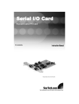
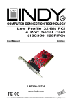
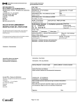
1
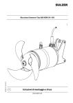
4233A 4243A 8243 8233 RS-232/422/485 PC/104 Module _______________________________ User’s Manual First Edition, July 2005 SUNIX Co., Ltd. Tel : +886-2-8913-1987 Fax: +886-2-8913-1986 Http://www.sunix.com.tw [email protected] RS-232/422/485 PC/104 Module User’s Manual Copyright Copyright© 2005 SUNIX Co., Ltd. All Rights Reserved. No part of this publication may be reproduced, transcribed, stored in a retrieval system, translated into any language, or transmitted in any from or by any means, photocopying, manual, or otherwise, without prior written permission from SUNIX Co., Ltd. Disclaimer SUNIX Co., Ltd. Shall not be liable for any incidental or consequential damages resulting from the performance or use of this equipment. SUNIX Co., Ltd. makes no representations or warranties regarding the contents of this manual. Information in this manual has been carefully checked for reliability; however, no guarantee is given as to the correctness of this content. In the interest of continued product improvement, this company reserves the right to revise the manual or include change in the specifications of the product described within it at any time without notice and without obligation to notify any person of such revision or changes. The information contained in this manual is provided for general use by the customers. Trademarks SUNIX is a registered trademark of SUNIX Co., Ltd. Other registered marks used herein are for identification purposes only and may be trademarks of their respective owners. Safety Information 1. Keep this User’s Manual for future reference. 2. Always read the safety information carefully. 3. Keep this equipment away from direct sunlight, or in humid or damp places. 4. Do not place this equipment in an unstable position, or on vibrating surface before setting it up. 5. Do not use or place this equipment near magnetic fields, televisions, or radios to avoid electronic interface that affects device performance. 6. Do not attempt to disassemble or repair the equipment or the warranty would be useless. 7. To avoid damaging your system and equipment, please make sure that your computer is off before you install the product. INDEX Chapter 1 Introduction............................................................................................1-1 Overview ................................................................................................... 1-2 Package Checklist .................................................................................... 1-2 Product Features....................................................................................... 1-3 Product Specifications .............................................................................. 1-4 Chapter 2 Hardware Installation.............................................................................2-1 Hardware Installation................................................................................. 2-2 Mechanical Drawings of RS-232 PC/104 Serial Board.............................. 2-3 Jumper and Connectors of RS-232 PC/104 Serial Board.......................... 2-4 Mechanical Drawings of RS-422/485 PC/104 Serial Board....................... 2-5 Jumper and Connectors of RS-422/485 PC/104 Serial Board................... 2-6 I/O Address and IRQ Setting ..................................................................... 2-7 Pin Assignment .......................................................................................... 2-8 Chapter 3 Software Installation .............................................................................3-1 Windows 2000/XP/2003.............................................................................. 3-2 Windows 95/98/ME.................................................................................... 3-24 Windows NT ..............................................................................................3-32 WinCE....................................................................................................... 3-39 Linux.......................................................................................................... 3-47 Chapter 4 Trouble Shooting ..................................................................................4-1 Appendix ……………………………................................................................................5-1 1. Introduction ______________________________________________ Thanks for purchasing PC/104 compatible RS-232 or RS-422/485 serial interface module that combines small size, industrial grade construction and reliability specifications, plus perform the functions most commonly need in embedded application. Because PC/104 modules use as smart stacking bus design, they avoid the costs and bulk associated with backplanes or card cage. Its work with PC/104 CPU boards that accept the PC/104 expansion interface, and comes with DB9 or DB25 connection cables are available as options to meet users' varied connection requirements. The following topics covered in this chapter: Overview Package Checklist Product Features Product Specifications 1-1 Overview This Multi-port PC/104 serial module equips with 2 or 4 ports high speed RS-232 or RS-422/485 standard serial ports which accessed through DB-9 or DB-25 male connectors. You can configure the I/O base address and interrupt vector of each serial port. Each serial port has built-in 64 byte hardware FIFO, and provides data transfer speed up to 921Kb/Sec with industry standard 16C750 asynchronous communication chip. Package Checklist Please check if the following items are present and in good condition upon opening your package. Contract your vendor if any item is damaged or missing. 1. Hardware: Serial Communication Board: Multi-port PC/104 serial module × 1 Cable: 2 ports PC/104 series: 2x5 IDC socket to DB9 or DB25 Male × 2 4 ports PC/104 series: 2x5 IDC socket to DB9 or DB25 Male × 4 2. CD Driver 3. Quick Installation Guide 4. User's Manual 1-2 (This document) Product Features RS-232 z z z z z z z z z 2 or 4 independent RS-232 serial ports Single chip SUN1699 (16C750 compatible) hardware flow control Each serial port has built-in 64 byte hardware FIFO Low repair rate with ASIC design Data transmission speeds up to 921.6Kbps IRQ and I/O address selectable for each serial port by jumper Ideal for PC/104 embedded systems Support DOS, Linux, Microsoft WinCE.NET, 3.x, 95, 98, Me, NT, 2000, XP, and 2003 Operation temperature: 0 to 60 ℃ & Storage Temperature: -20 to 85℃ RS-422/485 z z z z z z 2 or 4 independent RS-422/485 serial ports Single chip SUN1699 (16C750 compatible) hardware flow control Each serial port has built-in 64 byte hardware FIFO Automatic RS-485 RTS signal control technology Support Auto Detect and Switch RS-422 and RS-485 RTS/CTS± Handshaking Communication mode for RS-422/485 z z Data transmission speeds up to 921.6Kbps Built-in termination resistors to avoid cross-talking z z z IRQ and I/O address selectable for each serial port by jumper Ideal for PC/104 embedded systems Support DOS, Linux, Microsoft WinCE.NET, 3.x, 95, 98, Me, NT, 2000, XP, and 2003 Operation temperature: 0 to 60 ℃ & Storage Temperature: -20 to 85℃ z NOTE: You can get more core technology detail in Appendix chapter. 1-3 Product Specifications RS-232 z Function Type PC/104 RS-232 Module Mode of Operation Hand-Shaking Bus Transceivers RS-232 Full-Duplex Drivers per Line RS-232 1 Driver Receivers per Line RS-232 1 Receivers z Hardware IC SUN1699 Controller 16C750 compatible UART Bus Interface PC/104 Number of Ports 2 or 4 ports Connector Box Header z Communication Interrupt IRQ 3, 4, 5, 7, 9, 10, 11, 12, 15 I/O address 3F8, 3E8, 2F8, 2E8, 260, 268, 250, 258, 240, 248, 230, 238 FIFO 64 byte hardware FIFO Baud rate 75bps ~ 921.6 Kbps Data bit 5,6,7,8 Stop bit 1,1.5,2 Parity even, odd, none, mark, space Flow Control None, Xon/Xoff, Hardware Signal TxD, RxD, RTS, CTS, DTR, DSR, DCD, RI, GND z Driver support Driver Support Microsoft Windows CE4.2/CE5.0/3.x/95/98SE/Me/NT/2000/XP/2003 DOS, Linux 2.0.x / 2.2.x / 2.4.x z Dimensions Dimensions (W × D) z Regulatory Approvals Regulatory Approvals 1-4 95.9 × 90.2 mm CE, FCC RS-422/485 z Function Type PC/104 RS-422/485 Module Mode of Operation Differential Bus Transceivers Drivers per Line Receivers per Line z RS-422 Full-Duplex RS-485 Half-Duplex RS-422 1 Driver RS-485 10 Drivers RS-422 10 Receivers RS-485 32 Receivers Hardware IC SUN1699 Controller 16C750 compatible UART Bus Interface PC/104 Number of Ports 2 or 4 ports Connector Box Header z Communication Interrupt IRQ 3, 4, 5, 7, 9, 10, 11, 12, 15 I/O address 3F8, 3E8, 2F8, 2E8, 260, 268, 250, 258, 240, 248, 230, 238 FIFO 64 byte hardware FIFO RS-485 Control This ARSC™ (Auto RTS Signal Control) technology Select RS-422/485 Auto Switch RS-422/485 technology Baud rate 75bps ~ 921.6 Kbps Data bit 5,6,7,8 Stop bit 1,1.5,2 Parity even, odd, none, mark, space Flow Control None, Xon/Xoff, Hardware Signal RS-422: TxD+/-, RxD+/-, RTS+/-, CTS+/-, GND RS-485:Data+/-, RxD+/-, RTS+/-, CTS+/-, GND z Driver support Driver Support Microsoft Windows CE4.2/CE5.0/3.x/95/98SE/Me/NT/2000/XP/2003 DOS, Linux 2.0.x / 2.2.x / 2.4.x z Dimensions Dimensions (W × D) z 95.9 × 90.2 mm Regulatory Approvals Regulatory Approvals CE, FCC 1-5 2. Hardware Installation ______________________________________________ This chapter includes information about hardware installation for PC/104 module. The following topics are covered: Hardware Installation Mechanical Drawings Jumper and Connectors I/O Address & IRQ Settings Pin Assignments 2-1 Hardware Installation The hardware installation of PC/104 serial boards is easy to carry out. Before you insert the card into the PC/104 interface, you must first configure I/O Base Address & Interrupt Vector, and IRQ Settings. Follow the detailed steps given below to install the PC/104 serial board in your computer. Step 1: Configure I/O Base Address & IRQ Settings (see details below). Safety First To avoid damaging your system and boards, make sure your PC’s power is turned off before installing your PC/104 module. Step 2: Turn your PC’s power off, and also shut off the power to any peripheral devices, and then remove the PC’s cover. Step 3: Insert the PC/104 serial module into the PC/104 interface slot. Step 4: Fasten the holding screw to fix the serial board in place. Step 5: Replace the PC’s cover. Step 6: Power on the PC. . 2-2 Mechanical Drawings of RS-232 PC/104 Serial Board RS-232 4 ports PC/104 Serial Board 2 ports PC/104 Serial Board 2-3 Jumper and Connectors of RS-232 PC/104 Serial Board Label S1 S2 S3 S4 Connectors Function RS-232 Port 1 RS-232 Port 2 RS-232 Port 3 RS-232 Port 4 Label JP1 JP2 JP3 JP4 JP5 JP6 JP7 JP8 Jumpers Function Port 1 IRQ Select Port 2 IRQ Select Port 3 IRQ Select Port 4 IRQ Select Port 1 I/O Address Select Port 2 I/O Address Select Port 3 I/O Address Select Port 4 I/O Address Select 2-4 Mechanical Drawings of RS-422/485 PC/104 Serial Board RS-422/485 4 ports PC/104 Serial Board 2 ports PC/104 Serial Board 2-5 Jumper and Connectors of RS-422/485 PC/104 Serial Board Label S1 S2 S3 S4 Connectors Function RS422/485 Port 1 RS422/485 Port 2 RS422/485 Port 3 RS422/485 Port 4 Jumpers Label Function JP1 Port 1 IRQ Select JP2 Port 2 IRQ Select JP3 Port 3 IRQ Select JP4 Port 4 IRQ Select JP6 Port 1 I/O Address Select JP7 Port 2 I/O Address Select JP9 Port 3 I/O Address Select JP10 Port 4 I/O Address Select 2-6 I/O Address & IRQ Settings Please make sure the IRQ and I/O address settings on your PC/104 system before setting PC/104 serial board jumpers. There will be a conflict when users set the same parameter in different ports. The I/O base address settings of PC/104 serial board are selectable by JP5~8 jumpers for port1 to port4. Before you insert a PC/104 serial board into the PC/104 interface, you need to choose an available jumper from 3F8, 2F8, 3E8, 2E8, 250, 258, 260, 268, 240, 248, 230, or 238 to configure the I/O address setting. The IRQ settings of PC/104 serial board are selectable by JP5~8 jumpers for port1 to port4. Before you insert a PC/104 serial board into the PC/104 interface, you need to choose an available jumper from 3, 4, 5, 7, 9, 10, 11, 12, or 15 to configure the IRQ setting. 2-7 Pin Assignment 2-8 3. Software Installation ______________________________________________ After installing the PC/104 serial module in your system successfully, please follow the step by step software installation guide to confirm how to install appropriate driver and configure the serial port settings. The driver for PC/104 serial board supports various operating systems, and you can select your requirement in the following chapter: The following topics covered in this chapter: 3-1 Windows 2000/XP/2003 Windows 95/98/Me Windows NT Windows CE.NET Linux Windows 2000/XP/2003 Checking system resource Please check available I/O and IRQ resources before installing the hardware. 1. Click Start Æ Control Panel Æ System 2. Click the “Hardware” tab page, and click “Device Manager”. 3-2 3. Click View Æ Resources by type. 3. Click “Interrupt request (IRQ)” showing IRQ sub tree to check if any unused IRQ resources available. 4. Click “Input/output (IO)” showing IO sub tree to check if any unused IO resources available. 5. Setup the jumper setting on PC/104 serial board by using available IRQ & IO resource. 3-3 Installing PC/104 Serial board Driver 1. Click Start Æ Control Panel Æ Add/Remove Hardware 2. The Add/Remove Hardware Wizard window will open next. Click on Next to continue. 3-4 3. When the Choose a Hardware Task window opens, please select “Add/Troubleshoot a device”, and then click on “Next” to continue. 4. The New Hardware Detection window will search PC/104 serial board on your computer. 5. When the Choose a Hardware Device window opens, select “Add a new device” and then click “Next” to continue. 3-5 6. The Find New Hardware window will open next. Select “No, I want to select the hardware from a list”, since PC/104 is a brand new type of ISA serial board, and then click on “Next” to continue. 7. When the Hardware Type window opens, select “Multi-port serial adapters” under Hardware types, and then click on “Next” to continue. 3-6 8. When the Select a Device Driver window opens, click on “Have Disk” to install driver from the CD driver that came with the PC/104 serial board. 9. Click “Browse..”, and specify the driver locate within the CD driver as bound with PC/104 serial board. CD/DVD ROM: \IO\ISA IO\Win2000,XP,2003\ 3-7 10. Explore the driver CD and select “twisaser.inf” and click “Open”. 11. Click “OK” to continue driver installation steps. 3-8 12. When the Select a Device Driver window opens, select PC/104 serial board type from the list and click “Next” to continue. Here is an example by selecting “2 ports Serial Communication Board”. Note: The following windows will show in Windows 2000 only. (1)Click “OK” to continue. (2)Click “Cancel” to ignore to the hardware setting. 3-9 13. The Start Hardware Installation window will open next and click “Next”. 14. A Digital Signature Not Found window will open. Although this message states that this PC/104 serial board driver does not contain a Microsoft digital signature, you can rest assured, since the driver has already been tested and been shown that it can support Windows OS. Click “Yes” to continue the installation. 3-10 15. Click “Finish” to end the PC/104 serial board installation. Installing PC/104 Serial port Driver 1. New Hardware Wizard will pop-up for new arrived port devices. Click “Next” to continue to driver installing. 3-11 2. When the Install Hardware Device Drivers window opens, select “Search for a suitable driver for my device (recommended)” for SUN1699 serial port installation. Click “Next” to continue. 3. When the Locate Driver Files window opens, select “specify a location” and click “Next” to install driver from the CD driver. 3-12 4. Click “Browse..”, and specify the driver locate within the CD driver as bound with PC/104 serial board. Click “OK” to continue. CD/DVD ROM: \IO\ISA IO\Win2000,XP,2003\ 5. When the Driver Files Search Results window opens, system will install driver for SUN1699 serial port. Click “Next” to continue. 3-13 6. Click “Finish” to end PC/104 serial board serial port installation steps. The New Hardware Wizard will popup several times, and you should repeat Installing PC/104 Serial port Driver steps for every individual ports. 7. Please click “Yes” to restart you computer after each serial ports are installed successfully. NOTE: For the successful case, the hardware settings just match the resources assigned by the OS. For the failed case, we will modify the default IRQ and IO settings later. You can ignore the “Code10” error message which shown in end of PC/104 serial board serial port installation steps. 3-14 Setting IO & IRQ in PC/104 Serial port Driver The following procedure explains how to resolve the hardware resources mismatch problems. 1. Please launch the “Device Manager” from Start Æ Control Panel Æ System 2. Expand the “Ports” sub-tree to see if any “SUN1699 Serial Port” is with an exclamation mark. Expand the “Multi-port serial adapters” sub-tree, and right-click the “2 ports Serial Communication Board” item, and choose “Porperties”. 3-15 3. Click “Board Information” tab page to see the default resource assignments. Keep in mind the current resources settings for each child serial ports. 4. Click “Resources” tab page to modify the default resource assignments, and un-check the “Use automatic settings” checkbox. 3-16 5. Select “Basic configuration 001” from the “Setting based on” list. 6. Choose the in-correct “Input/Output Range” in Resource Type item from Resource Settings list, and click “Change setting…”. 3-17 7. Select an available and correct “Value” (It depends on the hardware jumper setting.) including IO and IRQ settings and click “OK”. Be careful, to avoid the resource conflicting by referring “conflict information”. If the hardware settings conflict with the other device’s resources, please re-configure your hardware jumper settings before continuing. You should repeat select IO & IRQ settings for every individual ports. 7. Click “Yes” to use manually forced setting. 8. The Device Manager will start to re-install the child serial ports. It is not necessary to reboot the PC. 3-18 9. The exclamation mark of the serial port should be removed if your forced resource settings match with the hardware configuration. The serial port is ready for using. 10. You can confirm the IO and IRQ settings in “Board Information” tab page. 3-19 Configure the Serial Port Settings 1. Please launch the “Device Manager” from Start Æ Control Panel Æ System 2. Right click the “SUN1699 Serial Port (COMXXX)” item from the “Ports” sub-tree and click “Properties”. 3. Click “Port Settings” tab page and click “Advanced” for advanced settings. 3-20 4. Click “Defaults” button for restoring default advanced settings. 5. Check/un-check the “Enable CTS/RTS Auto Flow Control” checkbox to enable/ disable the hardware auto flow control feature. 3-21 6. Check/Un-check the “Use FIFO buffers control” checkbox to enable / disable the hardware FIFO buffering feature or you can select the size of FIFO if “Use FIFO buffers control” is enabled. 7. Re-map the COM port number by select a free COM port number from the “COM Port Number” combo box. The (in use) means this COM port number is used by another COM port. 3-22 Uninstalling Device 1. Please launch the “Device Manager” from Start Æ Control Panel Æ System 2. Expand the “Multi-port serial adapter” sub-tree and right-click the mouse on “x ports Serial Communication Board” item, and select “Uninstall”. 3. A “Confirm Device Removal” Warning window will open. Click “OK” to uninstall the device. 3-23 Windows 95/98/Me The following procedure is for installing PC/104 serial board driver under Windows 95/98/ME. Installing Driver 1. Please insert the CD Driver bound with PC/104 serial board into your CD/ DVD ROM, and then run under the Setup.exe program CD/DVD ROM: \IO\ISA IO\Win9x\Setup.exe 2. Please click “OK” to install driver. 3-24 3. Please click “Next” to install driver. 4. Please click “Finish” to install driver. 5. Double click “Multi-I/O Card Configuration” in control panel. 3-25 6. Press “Add” to add new model in ISA Multi I/O Card configuration winodws. 7. Select the model, and press “Select”. 4 ports RS-232 or RS-422/485 Æ ISA 4043A 2 ports RS-232 or RS-422/485 Æ ISA 4033A 4 16C750 (64FIFO) 2 16C750 (64FIFO) 8. Select the IRQ and I/O Address as the hardware jumper setting and press “Install”. 3-26 9. Click “Close” if the installation is finished. 10. This PC/104 serial board had been installed in your system. (a)Click “Add”, if you have another ISA card to install, select the card modem and click “Select” and repeat the installation step from step5. (b) Click “Config” to view or modify the IRQ or I/O address settings. (c) Click “Remove” to remove the selected card installation. (d) Click “Exit” to finish the setting. 11. Please restart your computer to make the settings working. 3-27 Hardware Installation Verity 1. Please launch the “System” from Start Æ Control Panel Æ System 2. Expand the “MultiIO Controller” and “Ports [COM & LPT]” sub-tree to see “ISA 4043A Multi-I/O Adapter” and “ISA Serial Port [COMXXX] “ in Device Manager tab page. 3-28 Configure the Serial Port Settings 1. Please launch the “Device Manager” from Start Æ Control Panel Æ System 2. Right click the “ISA Serial Port [COMXXX]” item from the “Ports” sub-tree and click “Properties”. 3. Click “Port Settings” tab page and click “Advanced” for advanced settings. 3-29 4. Click “Defaults” button for restoring default advanced settings. 5. Check/un-check the “Enable CTS/RTS Auto Flow Control” checkbox to enable/ disable the hardware auto flow control feature. 6. Check/Un-check the “FIFO buffers control” checkbox to enable / disable the different hardware FIFO buffering features, and you can select the accurate Receive/Transmit buffer size of FIFO in control bar. 3-30 Uninstalling Device 1. Please launch the “Device Manager” from Start Æ Control Panel Æ System 2. Expand the “Multi-port serial adapter” sub-tree and right-click the mouse on “ISA 4043A Multi-I/O Adapter” item, and select “Remove”. 3. A “Confirm Device Removal” Warning window will open. Click “OK” to uninstall the device. 3-31 Windows NT The following procedure is for installing PC/104 serial board driver under Windows NT. Installing Driver 1. Please insert the CD Driver bound with PC/104 serial board into your CD/ DVD ROM, and then run under the Setup.exe program CD/DVD ROM: \IO\ISA IO\WinNT\Setup.exe 2. Press “Continue” to install the driver. 3. Click “OK” to reboot computer to load the new installed driver to NT. 3-32 4. Double click “Multi-I/O Card Configuration” in control panel. 5. Press “ISA Multi-I/O Setup” tab page in Multi-I/O Configuration Utility. 6. Press “Add” to add new model. 7. Select the model, and press “Select”. 4 ports RS-232 or RS-422/485 Æ ISA 4043A 2 ports RS-232 or RS-422/485 Æ ISA 4033A 3-33 4 16C750 (64FIFO) 2 16C750 (64FIFO) 8. Select the IRQ and I/O Address as the hardware jumper setting and press “OK”. 9. This PC/104 serial board had been installed in your system. (a)Click “Add”, if you have another ISA card to install, select the card modem and click “Select” and repeat the installation step from step5. (b) Click “Delete” to remove the selected card installation (c) Click “Setup” to view or modify the IRQ or I/O address settings. (d) Click “OK” to finish the setting. 10. Please press “Yes” to restart your computer to make the settings working. 3-34 Configure Serial Port 1. Double click “Multi-I/O Card Configuration” in control panel. 2. Press “PCI/ISA Serial Port” tab page in Multi-I/O Configuration Utility. Select the COM port you want to configure (e.g. COM3), and click “Setup”. 3. Check/un-check the “Auto Flow Control” checkbox to enable/ disable the hardware auto flow control feature. 4. Check/Un-check the “FIFO buffers control” checkbox to enable / disable the different hardware FIFO buffering features, and you can select the accurate Receive buffer size of FIFO in “Receive Trigger Level”. 3-35 If your card can support 64 (32) bytes FIFO, you can use 16 or 32 or 64 (16 or 32) bytes FIFO. The default value is Use 16 Byte FIFO buffers. Auto Flow Control Enable means the CTS/RTS flow control is controlled by hardware automatically. System will be more stable if the function is enabled. Set the Receive Trigger Level to higher value will get faster performance because the interrupts will be reduced, but the time for interrupt service routine will become shorter. The receive buffer overflow will be easily happened if the CPU speed is not enough to handle. If the system is not stable, select the lower value to correct problems. Note: 1. If you stall the modem-using auto detect by Windows NT, the Auto Flow Control Enable shall be disabled. 2. When the serial I/O is 3F8, 2F8, 3E8, 2E8, the port driver is using WinNT default driver and can support 115200. When using other address, the driver must be installed and baud rate setting supports 921600bps. If you install 4 ports serial card, the order of port1 ~ port4 should be following the sequence of 3F8, 2F8, 3E8, 2E8, others, otherwise you may have trouble to identify port number. 3-36 Hardware Installation Verity 1. Please launch the “Windows NT Diagnostics” from Start Æ Programs Æ Administrative Tools [Common] Æ Windows NT Diagnostics 2 Please press “Resources” tab page and click “I/O Port. Yu can find the I/O address of four serial ports (SNXSER). Or you can find the IRQ information by press “IRQ” tab page. 3-37 Uninstalling Device 1. Double click “Add/Remove Programs” in control panel. 2. Select “Multi-I/O Card Uninstall” and click “Add/Remove” button. 3. Click “OK” to remove Multi-I/O card driver and click “OK” to reboot your PC. 3-38 Windows CE.NET This installation guide describes the procedures to install the PC/104 Serial Board in Microsoft Windows CE.NET (Ver4.2 or 5.0) operation system on x86 systems. Driver Compiling 1. Preparation prior to installation: Copy driver file into the your platform BSP "File" folder. \IO\ISA IO\WinCE\ (SUN1889.DLL, SUN1699.DLL, SerialCardControl.exe) Path Example : _WINCEROOT\Platform\MyBSP\File\ ("_WINCEROOT" is your platform builder folder name) ("MyBSP" is your platform BSP base name) 2. Prepare a hardware target platform: The platform setting must meet the following requirements. (1) If your motherboard have the standard serial port, then PC/104 Serial board IRQ and IO Base jump setting don't be like motherboard standard serial port please. (Serial board jump setting don't like this example : 02F8, 03E8, 02E8... IRQ3, IRQ4, IRQ5, and please reference your motherboard menu) Serial card jump setting can use of the other IOBase and IRQ. (2) In the motherboard BIOS setting, you must be to preserve IRQ for serial card. Example step (Phoenix - AwardBIOS): BIOS → PnP/PCI Configurateions → Resources Controlled By → change setting to "Manual". BIOS → PnP/PCI Configurateions → IRQ Resources → IRQ-10 assigned to → change setting to "Reserved". BIOS → PnP/PCI Configurateions → IRQ Resources → IRQ-11 assigned to → change setting to "Reserved". ...... 3-39 NOTE: ** If you sure, want use the same motherboard standard serial port IoBase or IRQ( 02F8, 03E8, 02E8... IRQ3, IRQ4, IRQ5) ** Then, Your motherboard standard serial port must be disabled, ** And also need to mark standard serial port registry in the platform.reg ** please follow [9.Other information] step(2). 3. Install Serial Card Driver for ISA Bus (1) please following [1. Preparation prior to installation] step, copy file into the directory first. (2) Edit the _WINCEROOT\Platform\MyBSP\Files\Platform.bib file, Insert CopyFile command into the MODULES section. ("_WINCEROOT" is your platform builder folder name) ("MyBSP" is your platform BSP base name) ;Example : SUN1699.dll $(_FLATRELEASEDIR)\SUN1699.dll SerialDriverControl.exe $(_FLATRELEASEDIR)\SerialDriverControl.exe NK SH NK SH (3) Edit the _WINCEROOT\Platform\MyBSP\Files\Platform.reg file, Insert your Serial Port setting of file end,you must setting for each port. ** Property illustration at [4.Other information]. ("_WINCEROOT" is your platform builder folder name) ("MyBSP" is your platform BSP base name) ;Example : ;Please puts Bus Driver setting in the PCI Template folder,ex:[HKEY_LOCAL_MACHINE\Drivers\BuiltIn\] ;----------------------------------------------------------------------; Sun1699 Serial Port Setting [HKEY_LOCAL_MACHINE\Drivers\BuiltIn\MySunSerial] "Prefix"="COM" "Dll"="SUN1699.Dll" "IoBase"=dword:0258 "IoLen"=dword:8 "SysIntr"=dword:1A 3-40 "DeviceArrayIndex"=dword:0 "Index"=dword:2 "EnableRTSCTSAutoFlowControl"=dword:0 "WaterMarkerMode"=dword:1 "WaterMarker"=dword:1C [HKEY_LOCAL_MACHINE\Drivers\BuiltIn\MySunSerial\Unimodem] "Tsp"="Unimodem.dll" "DeviceType"=dword:0 "FriendlyName"=LOC_FRIENDLYNAME_SERIAL2 "DevConfig"=hex: 10,00, 00,00, 05,00,00,00, 10,01,00,00, 00,4B,00,00, 00,00, 08, 00, 00, 00,00,00,00 ;----------------------------------------------------------------------;Example the second Port ;----------------------------------------------------------------------; Sun1699 Comm Card Driver Setting [HKEY_LOCAL_MACHINE\Drivers\BuiltIn\MySunSerial2] "Prefix"="COM" "Dll"="SUN1699.Dll" "IoBase"=dword:0260 "IoLen"=dword:8 "SysIntr"=dword:1B "DeviceArrayIndex"=dword:1 "Index"=dword:3 "EnableRTSCTSAutoFlowControl"=dword:0 "WaterMarkerMode"=dword:1 "WaterMarker"=dword:1C [HKEY_LOCAL_MACHINE\Drivers\BuiltIn\MySunSerial2\Unimodem] "Tsp"="Unimodem.dll" "DeviceType"=dword:0 "FriendlyName"=LOC_FRIENDLYNAME_SERIAL3 "DevConfig"=hex: 10,00, 00,00, 05,00,00,00, 10,01,00,00, 3 00,4B,00,00, 00,00, 08, 00, 00, 00,00,00,00 ;----------------------------------------------------------------------- 3-41 ;Example the three Port; ;----------------------------------------------------------------------; Sun1699 Comm Card Driver Setting [HKEY_LOCAL_MACHINE\Drivers\BuiltIn\MySunSerial3] "Prefix"="COM" "Dll"="SUN1699.Dll" "IoBase"=dword:0268 "IoLen"=dword:8 "SysIntr"=dword:1C "DeviceArrayIndex"=dword:2 "Index"=dword:4 "EnableRTSCTSAutoFlowControl"=dword:0 "WaterMarker"=dword:1C "WaterMarkerMode"=dword:1 [HKEY_LOCAL_MACHINE\Drivers\BuiltIn\MySunSerial3\Unimodem] "Tsp"="Unimodem.dll" "DeviceType"=dword:0 "FriendlyName"=LOC_FRIENDLYNAME_SERIAL4 "DevConfig"=hex: 10,00, 00,00, 05,00,00,00, 10,01,00,00, 00,4B,00,00, 00,00, 08, 00, 00, 00,00,00,00 ;----------------------------------------------------------------------(4) Build your platform system. 4. Other information If you sure, want use the same motherboard standard serial port IoBase or IRQ( 02F8, 03E8, 02E8... IRQ3, IRQ4, IRQ5). Then, Your motherboard standard serial port must be disabled, and you need to mark standard serial port registry in the platform.reg . Please following step and reference Windows CE menu. (1) Disabled motherboard step. BIOS → CHIPSET FEATURES SETUP → Onboard Serial Port 1→ change setting to disabled. 3-42 BIOS → CHIPSET FEATURES SETUP → Onboard Serial Port 2→ change setting to disabled. BIOS → CHIPSET FEATURES SETUP → Parallel Port → change setting to disabled. (2) Mark standard serial port registry. please open platform.reg. Find string "[HKEY_LOCAL_MACHINE\Drivers\BuiltIn\Serial]" You will find this section. ; @CESYSGEN IF CE_MODULES_SERIAL IF BSP_NOSERIAL ! [HKEY_LOCAL_MACHINE\Drivers\BuiltIn\Serial] "SysIntr"=dword:13 "IoBase"=dword:02F8 "IoLen"=dword:8 "DeviceArrayIndex"=dword:0 "Prefix"="COM" "IClass"="{CC5195AC-BA49-48a0-BE17-DF6D1B0173DD}" "Dll"="Com16550.Dll" "Order"=dword:0 "Priority"=dword:0 ; Turn on follows for Installable ISR (isr16550 supporting SOFTWARE FIFO ; "Irq"=dword:3 ; "IsrDll"="isr16550.dll" ; "IsrHandler"="ISRHandler" [HKEY_LOCAL_MACHINE\Drivers\BuiltIn\Serial\Unimodem] "Tsp"="Unimodem.dll" "DeviceType"=dword:0 "FriendlyName"=LOC_FRIENDLYNAME_SERIAL "DevConfig"=hex: 10,00, 00,00, 05,00,00,00, 10,01,00,00, 00,4B,00,00, 00,00, 08, 00, 00, 00,00,00,00 ENDIF BSP_NOSERIAL ! 3-43 IF BSP_SERIAL2 [HKEY_LOCAL_MACHINE\Drivers\BuiltIn\Serial2] "SysIntr"=dword:14 "IoBase"=dword:03E8 "IoLen"=dword:8 "DeviceArrayIndex"=dword:1 "Prefix"="COM" "IClass"="{CC5195AC-BA49-48a0-BE17-DF6D1B0173DD}" "Dll"="Com16550.Dll" "Order"=dword:0 [HKEY_LOCAL_MACHINE\Drivers\BuiltIn\Serial2\Unimodem] "Tsp"="Unimodem.dll" "DeviceType"=dword:0 "FriendlyName"=LOC_FRIENDLYNAME_SERIAL2 "DevConfig"=hex: 10,00, 00,00, 05,00,00,00, 10,01,00,00, 00,4B,00,00, 00,00, 08, 00, 00, 00,00,00,00 ENDIF BSP_SERIAL2 IF BSP_SERIAL3 [HKEY_LOCAL_MACHINE\Drivers\BuiltIn\Serial3] "SysIntr"=dword:15 "IoBase"=dword:02E8 "IoLen"=dword:8 "DeviceArrayIndex"=dword:2 "Prefix"="COM" "IClass"="{CC5195AC-BA49-48a0-BE17-DF6D1B0173DD}" "Dll"="Com16550.Dll" "Order"=dword:0 [HKEY_LOCAL_MACHINE\Drivers\BuiltIn\Serial3\Unimodem] "Tsp"="Unimodem.dll" "DeviceType"=dword:0 "FriendlyName"=LOC_FRIENDLYNAME_SERIAL3 "DevConfig"=hex: 10,00, 00,00, 05,00,00,00, 10,01,00,00, 00,4B,00,00, 00,00, 08, 00, 00, 00,00,00,00 ENDIF BSP_SERIAL3 3-44 (3) Please use ";" character mark all registry. IF BSP_NOSERIAL ! ;[HKEY_LOCAL_MACHINE\Drivers\BuiltIn\Serial] ; "SysIntr"=dword:13 ; "IoBase"=dword:02F8 ; "IoLen"=dword:8 ; "DeviceArrayIndex"=dword:0 ; "Prefix"="COM" ; "IClass"="{CC5195AC-BA49-48a0-BE17-DF6D1B0173DD}" ; "Dll"="Com16550.Dll" ; "Order"=dword:0 ; "Priority"=dword:0 ;; Turn on follows for Installable ISR (isr16550 supporting SOFTWARE FIFO ;; "Irq"=dword:3 ;; "IsrDll"="isr16550.dll" ;; "IsrHandler"="ISRHandler" ;[HKEY_LOCAL_MACHINE\Drivers\BuiltIn\Serial\Unimodem] ; "Tsp"="Unimodem.dll" ; "DeviceType"=dword:0 ; "FriendlyName"=LOC_FRIENDLYNAME_SERIAL ; "DevConfig"=hex: 10,00, 00,00, 05,00,00,00, 10,01,00,00, 00,4B,00,00, 00,00, 08, 00, 00, 00,00,00,00 ENDIF BSP_NOSERIAL ! IF BSP_SERIAL2 ;[HKEY_LOCAL_MACHINE\Drivers\BuiltIn\Serial2] ; ; ; ; ; ; ; ; 3-45 "SysIntr"=dword:14 "IoBase"=dword:03E8 "IoLen"=dword:8 "DeviceArrayIndex"=dword:1 "Prefix"="COM" "IClass"="{CC5195AC-BA49-48a0-BE17-DF6D1B0173DD}" "Dll"="Com16550.Dll" "Order"=dword:0 ;[HKEY_LOCAL_MACHINE\Drivers\BuiltIn\Serial2\Unimodem] ; "Tsp"="Unimodem.dll" ; "DeviceType"=dword:0 ; "FriendlyName"=LOC_FRIENDLYNAME_SERIAL2 ; "DevConfig"=hex: 10,00, 00,00, 05,00,00,00, 10,01,00,00, 00,4B,00,00, 00,00, 08, 00, 00, 00,00,00,00 ENDIF BSP_SERIAL2 IF BSP_SERIAL3 ;[HKEY_LOCAL_MACHINE\Drivers\BuiltIn\Serial3] ; "SysIntr"=dword:15 ; "IoBase"=dword:02E8 ; "IoLen"=dword:8 ; "DeviceArrayIndex"=dword:2 ; "Prefix"="COM" ; "IClass"="{CC5195AC-BA49-48a0-BE17-DF6D1B0173DD}" ; "Dll"="Com16550.Dll" ; "Order"=dword:0 ;[HKEY_LOCAL_MACHINE\Drivers\BuiltIn\Serial3\Unimodem] ; "Tsp"="Unimodem.dll" ; "DeviceType"=dword:0 ; "FriendlyName"=LOC_FRIENDLYNAME_SERIAL3 ; "DevConfig"=hex: 10,00, 00,00, 05,00,00,00, 10,01,00,00, 00,4B,00,00, 00,00, 08, 00, 00, 00,00,00,00 ENDIF BSP_SERIAL3 (4) SerialDriverControl.exe application reference "Microsoft Foundation Classes (MFC)" Library, your platform must be include this item.(use catalog add this item) (please reference Windows CE menu) 3-46 Linux This installation guide describes the procedure to install SUNIX ISA serial ports in Linux platform. Linux Platform Operating System : RedHat V6.0/V5.2 (Kernel 2.2.5 / 2.0.36) Terminal Emulation AP : minicom Internet Dialer : Kppp Installation Steps 1. Find the available serial ports Since Linux only support 4 serial ports (ttyS0, ttyS1, ttyS2, ttyS3) under the default condition. Most likely, ttyS0 & ttyS1 are supported by mother board's built-in 16550 controllers and ttyS2 & ttyS3 are free for additional I/O card. (Note that ttyS2: S is upper case) It could be checked by the following commands. #setserial /dev/ttyS0 -a (COM1) #setserial /dev/ttyS1 -a (COM2) #setserial /dev/ttyS2 -a (COM3) #setserial /dev/ttyS3 -a (COM4) If COM1 is used by mouse, the response is similar to /dev/ttyS0 : Device or resource busy If the COM1 does not attach any device, the response is similar to /dev/ttyS0, Line 0, UART: 16550A, Port: 0x3f8, irq: 4 Baud_base: 115200, clos_delay: 50, divisor: 0 closing_wait: 3000, closing_wait2: infinite Flags: spd_normal skip_test In case ttyS2 (COM3) is free, the response for command # setserial /dev/ttyS2 -a is shown below. 3-47 /dev/ttyS2, Line 2, UART: unknown, Port: 0x3e8, irq: 4 Baud_base: 115200, clos_delay: 50, divisor: 0 closing_wait: 3000, closing_wait2: infinite Flags: spd_normal skip_test (note that UART: unknown) In case ttyS3 (COM4) is free, the response for command # setserial /dev/ttyS3 -a is shown below. /dev/ttyS3, Line 3, UART: unknown, Port: 0x2e8, irq: 3 Baud_base: 115200, clos_delay: 50, divisor: 0 closing_wait: 3000, closing_wait2: infinite Flags: spd_normal skip_test (note that UART: unknown) Finally, the /dev/ttyS2 & /dev/ttyS3 are free for ISA serial ports. 2. Check the ISA serial port's jumper setting ( I/O port address & IRQ) All ISA serial port I/O address is allowed to be one of the following location. 3F8h 2F8h 3E8h 2E8h 230h 238h 240h 248h 250h 258h 260h 268h All ISA serial port interrupt is allowed to be one of the following IRQ. IRQ 3, 4, 5, 7, 9, 10, 11, 12,15 3. Configure the parameters for ttyS2 & ttyS3 For 1 port serial port board, please enter (if ttyS2 is free and jumper setting is 3E8h / IRQ10) # setserial /dev/ttyS2 port 0x3E8 UART 16550A irq 10 Baud_base 115200 For 2 ports serial port board, please enter (if ttyS2 & ttyS3 are free and jumper setting are 3E8h / IRQ10 & 2E8 / IRQ11) # setserial /dev/ttyS2 port 0x3E8 UART 16550A irq 10 Baud_base 115200 # setserial /dev/ttyS3 port 0x2E8 UART 16550A irq 11 Baud_base 115200 3-48 4. Check the setting for ttyS2 & ttyS3 Please enter # setserial /dev/ttyS2 -a The Linux's response look likes below /dev/ttyS2, Line 2, UART: 16550A, Port: 0x3E8, irq: 10 Baud_base: 115200, clos_delay: 50, divisor: 0 closing_wait: 3000, closing_wait2: infinite Flags: spd_normal skip_test 5. Then the ttyS2 & ttyS3 are ready for application (eg. minicom -s or xminicom -s or Kppp ...) 6. In case more than 4 serial ports are needed If there are more than 4 serial ports to be supported by Linux system, the first step is to add more tty device nodes into system. Inquire the system tty device nodes, #ls -al /dev/ttyS* crw------- 1 root tty 4, 64 Jan 8 11:40 /dev/ttyS0 crw------- 1 root tty 4, 65 Jan 8 11:40 /dev/ttyS1 crw------- 1 root tty 4, 66 Jan 8 11:40 /dev/ttyS2 crw------- 1 root tty 4, 67 Jan 8 11:40 /dev/ttyS3 Add tty device node one by one #mknod /dev/ttyS4 c 4 68 (for ttyS4) #mknod /dev/ttyS5 c 4 69 (for ttyS5) #mknod /dev/ttyS6 c 4 70 (for ttyS6) #mknod /dev/ttyS7 c 4 71 (for ttyS7) …………………………. Please add all tty device nodes accordingly Configure the parameters for all new ttyS* Please repeat step 2, 3, and 4 to set the correct parameters for each tty device. Because all the new added tty device nodes are still invalid by default. 3-49 Re-Inquire the system tty device nodes, #ls -al /dev/ttyS* crw------- 1 root tty 4, 64 Jan 8 11:40 /dev/ttyS0 crw------- 1 root tty 4, 65 Jan 8 11:40 /dev/ttyS1 crw------- 1 root tty 4, 66 Jan 8 11:40 /dev/ttyS2 crw------- 1 root tty 4, 67 Jan 8 11:40 /dev/ttyS3 crw-r--r-- 1 root root 4, 68 Jan 18 11:40 /dev/ttyS4 crw-r--r-- 1 root root 4, 69 Jan 18 11:40 /dev/ttyS5 …………………………. Notes : (1) For those tty devices which are sharing a interrupt pin within one card, you just set them the same IRQ number with setserial command. (2) Un-installation, e.g.#rm /dev/ttyS4 (remove ttyS4 device) 3-50 4. Troubleshooting ______________________________________________ This chapter shows some problems that user came with usually. Also you can check it if the PC/104 serial board can not work properly in your system after following hardware and software installation steps. 4-1 Troubleshooting 1. There are some exclamation marks in device manager and serial ports can not work properly. A: It caused by the wrong IRQ or IO settings. Those settings had conflicted with your system. (1) Please check the avaliable IRQ and IO addresss in your system. (2) Shot down your computer and check jumper settings fitting avaliable value on PC/104 serial board for every individual ports. (3) Remember your setting, and re-install PC/104 serial board dirver as descripted in chapter 3. NOTE: Please do NOT skip 3E8 and 2E8 IO address. If the system is already supporting two RS-232 ports (3F8 and 2F8) on mainboard and you want to install new serial port. You must install into Address 3E8 and 2E8 first, do not skip 3E8 and 2E8 and directly install into the following Addresses, 250, 258, 260, 268, 240, 248, 230, or 238. 2. Can I set the same IRQ with other PC/104 serial board or system? A: NO, you can not set the same IRQ or IO address same with other serial board or system. When you select IRQ, do not select the same IRQ as with other I/O card or system I/O port, because system performance and speed will be greatly reduced. This PC/104 serial board does not designed with IRQ sharing capability. 3. Do not test ISA Serial Port 16C750 chipset with QAPlus and CheckIT. A: Our ISA chipset SUN1699 use IN1 and IN2 to control the 16C550 (16 FIFO), 16C650 (32 FIFO), and 16C750 (64 FIFO) chipset. The QAPlus and CheckIT also use these two signals to check for the 16C550 status, when 16C550, we send IN1 and In2 as 0/0, so the test will pass, but with 16C650, we send IN1 and IN2 as 0/1, the QAPlus and CheckIT will receive different value, and so they think the 16C550 has MODEM Ctl ERROR and MODEM Status ERROR. For this error, only test program value define, it is not relevant for using our card in any system. Our card will work correctly with any device and on any system, do not worry about the error. 4-2 4. There is no enough IRQ in my system. A: If you install multi-port serial or parallel port, after installation, you will find yellow exclamation mark on "COM & LPT" in the Device Manager. This is because system IRQ is not enough; these cards don't have interrupter sharing capability, so each port needs one free IRQ. To correct this, go to "System" → "Device Manager" → "Computer" → "Interrupt Request" and check if there is any free interrupts and change the card's IRQ jumper to this free IRQ. If you cannot find free IRQ, your system use too much IRQ, and you must buy our other product for multi-port which uses only one IRQ (interrupter sharing card). 5. How large FIFO length I should set? A: PC/104 serial board supports 64 bytes FIFO, and you can use 16 or 32 or 64 bytes FIFO. The default value is 16 Byte FIFO buffers. Set the Receive/Transmit Buffer to higher value will get faster performance because the interrupts will be reduced, but the time for interrupt service routine will become shorter. The receive buffer overflow will be easily happened if the CPU speed is not enough to handle. If the system is not stable, select the lower value to correct problems. 6. Should I enable auto flow control features? A: Enable Auto CTS/RTS Flow Control means the CTS/RTS flow control is controlled by hardware automatically. System will be more stable if the function is enabled. 4-3 7. I forgot the model number that I can not install driver properly. A: When installing PC/104 serial board driver on your system, there will be a window showing model numbers for selecting. If you are confused with the model you bought, please following the instruction. (1) Windows 2000/XP/2003 Please select how many serial ports on PC/104 serial board. (2) Windows NT/95/98/Me Please select how many serial ports on PC/104 serial board. 4 ports RS-232 or RS-422/485 Æ ISA 4043A 2 ports RS-232 or RS-422/485 Æ ISA 4033A 4 16C750 (64FIFO) 2 16C750 (64FIFO) . 4-4 5. Appendix ______________________________________________ This chapter shows PC/104 serial board core technologies and shows you how to contact with us for information about this and other products. In this appendix, we cover the following topics. Core Technologies Contract Information 5-1 Core Technologies Our R&D team is experienced and expert at many advanced technologies needed for manufacturing highly- reliable data communication products. This PC/104 serial board equips many hardware and software features for users easily equipping in kinds of critical or harsh factory and industrial environment. It’s also the best solution for all of industrial communication and automation application. High Performance & Intelligent ASIC SUN1699 SUN1699 is a high performance and intelligent 167C50 UART. It’s not only for full compatibility with Microsoft OS series and Linux, but also allowing us to offer complete support for driver and technological change on the Serial RS-232 / 422 / 485. RS-422/485 Auto Identify & Switch Technology The unique circuit-designed RS-422/485 Auto Identify & Switch technology can automatically identify the state of RS-422 full-duplex or RS-485 half-duplex and control the data transceiver and receiver wires at the same port without selecting jumpers or switches anymore. It’s more convenient for users to avoid shutting down the computer and opening the chassis for jumpers or switches setting. 5-2 RS-485 ARSC™ Technology Due to the limitation of traditional RS-485 two wires half-duplex communication, system must determine when to switch the transmitter on and off. There is only one node can be switch on and off at any given time by software. ARSC™ (Auto RTS Signal Control) technology can identify the status of data transceiver or receiver and send RTS signal automatically, instead of using software/hardware to control the transmitter. This PC/104 RS-422/485 serial board has built-in ARSC™ technology now. System can manage the RS-485 ports without writing extra code to control the half-duplex protocol by using ARSC™ technology. Termination Resistors Building In When an electrical signal travels through two different resistance junctions in a transmission line, the impedance mismatch will sometimes cause signal reflection. Signal reflection causes signal distortion, which in turn contributes to communication errors. The solution to this problem is to establish the same impedance at the line ends as in the line itself by terminating them with resistors. It is normally sufficient when the value of the termination resistor equals the characteristic impedance of the transmission line. PC/104 RS-422/485 serial board builds in termination resistors to prevent those problems. 5-3 Optical Isolation Protection (Optional) The ground loop is a common problem in many industrial environments, especially in the state of ground voltage levels differ between connected devices in the type of critical or harsh factory environment when transmission line is long. Communications devices connected by long cables may be damaged by the mismatch between ground voltage levels at the two ends of the wire. Optical isolation uses photo cells at both ends of the line to isolate the devices' sensitive components from this type of electrical damage. PC/104 serial board provides 2.5KV optical isolation for power and signals to eliminate this kind of problem. Surge Protection (Optional) Surges are high amplitude electrical pulses lasting only several millionths of a second in duration. They can be caused by heavy-duty equipment, power lines, short circuits, or large motors. A surge suppressor has the ability to effectively absorb the high energy in an extremely short period of time, preventing the connected devices from damage. To eliminate this problem, we provide the embedded 600W surge protection for all signals. 5-4 Contract Information Customer satisfaction is our number one concern, and to ensure that customers receive the full benefit of our products, SUNIX services has been set up to provide technical support, driver updates, product information, and user’s manual updates. The following services are provided E-mail for technical support ................................... [email protected] World Wide Web (WWW) Site for product information: ............................http://www.sunix.com.tw 5-5