1
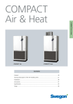
Compact Air
Room unit
Compact Air
Contents
Technical Description of the Air Handling Unit
General, Specification............................................................................................. 146
Function, Functional Sections................................................................................. 147
Control System
Control Display, Airflow Control............................................................................. 148
Temperature Control............................................................................................... 149
Special Functions..................................................................................................... 150
Accessories
One-week Timer, Occupant Detection Sensor, Electric Air Heater,
Exterior Wall Hood, Unit-to-ceiling Infill Piece...................................................... 151
Separate Lower Section, Air Distribution Plate, Extract Air Connection Piece... 152
Installation Tips
General Information about Temperature Control................................................. 153
Typical Installation in One or Several Rooms......................................................... 154
Sizing
Airflows and Acoustic Data..................................................................................... 155
Dimensions and Weights......................................................................................... 156
We reserve the right to alter specifications.
20060501
www.swegon.com
145
Compact Air
Description of the air handling unit
General
The Compact Air room unit is a complete air handling unit
with supply air and extract air fans, Supply air and extract
air filters, rotary heat exchanger, silencer and built-in lowvelocity air diffuser. The control equipment is also integrated into the unit.
The Compact Air unit is well-suited for use in classrooms,
day nurseries, conference halls, offices, workrooms,
shops, restaurants and similar public premises.
Compact Air is available in two capacity variants. The size
08 Compact Air units are designed for ventilating normal
classrooms and comparable rooms. The size 11 Compact
Air units are designed for ventilating larger rooms and/or
more than one room.
The unit should be installed in the room to be ventilated
and is connected to the mains by means of an electric
plug to an earthed electric socket. The ducts for outdoor
air and exhaust air should be connected to the top of
the unit and should be arranged to lead out through the
periphery wall.
The unit is automatically controlled between normal
airflow and low airflow by the timer or occupant detection sensor (accessories). The performance of the unit can
be checked and temporary changes can be entered via an
control display on the front of the unit.
The unit has a beige painted finish.
Extra Accessories
Compact Air Room Unit
Occupant detection sensor El. air heater, 1 kW. Exterior wall hood. One-week timer. Extract air connection.
Unit-to-ceiling infill piece. Separate lower unit section Air
distribution plate
Registered design. Registered trademark.
Replacement Material
Filter, 1 pc, F85/EU7
Specification
Compact Air Room Unit Size 08, 11
CACA-2-aa-bb
Language variant in the display
Swedish
Norwegian
Danish
= 21
Finnish
English
English
German
French
= 22
Extra Accessories
Occupant Detection Sensor
Electric air heater, 1 kW
Exterior Wall Hood
One-week timer
Extract Air Connection Piece
Unit-to-ceiling infill piece
Separate lower unit section
Air Distribution Plate
Variant 1, 2, 3, 4
Replacement Material
Filter, 1 pc, F85/EU7 146
We reserve the right to alter specifications.
20060501
CACZ-1-01
CACZ-1-02
CACZ-1-03
CACZ-1-05
CACZ-1-06
CACZ-1-07
CACZ-1-08
CACZ-1-10-a
CACZ-1-04-7
www.swegon.com
Compact Air
Description of the air handling unit
Operation
Wall hood
The Compact Air room unit is a complete
air handling unit designed for supplying air
according to the displacement ventilation
principle.
Outdoor air is supplied via a duct to the
unit where it passes through the filter, the
built-in silencer and the electric air heater,
if fitted. After that, the air passes through
the built-in silencer and is discharged via the
low-velocity air diffuser into the room.
OUTDOOR AIR
Supply air filter
EXTRACT
AIR
Extract air fan
In that the supply air has a slightly lower
temperature than the room air, the room air
is pressed upward toward the ceiling. The
Compact Air then sucks in extract air via an
intake at the top of the unit. The air passes
the silencer, filter and heat exchanger and is
then discharged via duct to the open air.
Silencer
Heat exchanger
Extract air filter
Supply air fan
The visible parts of the unit are painted in
a beige colour tone. The air handling unit
is mounted on base beams. A base plate,
painted black, is used to cover them. The
base plate is supplied in unmounted condition.
S UPPLY AIR
The inspection door is hung on hinges
secured to the left-hand edge. The door can
only be opened using a special key. When
the door is opened, a switch interrupts the power supply
to the fans and the heat exchanger.
Division into Sections
The Compact Air unit is always supplied as one complete
air handling unit. If transporting the unit within the site
proves difficult, the unit can be split into an upper section and a lower section. The fans, heat exchanger, filters,
intermediate level and inspection door can also easily be
dismantled from the upper section.
Airflows
To provide the best operating economy, the Compact Air
unit is designed for supplying a normal airflow while the
room is occupied and low-velocity airflow whenever the
room is unoccupied.
Size 11
For normal airflow, variable from 83 to 305 l/s (300-1,100
m3 /h). For low-velocity airflow, switched off or variable
from 83 to 305 l/s (300-1,100 m3 /h).
Filters
The Compact Air unit is equipped with ample fine filters
for both the supply air and the extract air. The filters are
disposable. Class F85/EU7 filters are used.
Heat Recovery
The rotary heat exchanger is of Reconomic type, patented
by Swegon. Its temperature efficiency is 84% at an airflow rate of 167 l/s (size 08) and 83% at 250 l/s (size 11).
The amount of heat required is controlled by automatically regulating the heat exchanger’s rotation speed.
Connection to Power Supply
The unit is connected to the mains by means of an electric
plug to an ordinary earthed, single-phase, 10 A, 230 V
socket-outlet.
The airflows can be preset as follows:
Size 08
For normal airflow, variable from 83 to 222 l/s (300-800
m3 /h). For low-velocity airflow, switched off or variable
from 83 to 222 l/s (300-800 m3 /h).
We reserve the right to alter specifications.
Compact Air
Low-momentum
air diffuser with
silencer
Casing
The unit casing is of double-skin design
with 30 mm thick insulation sandwiched
between sheet steel.
EXHAUST
AIR
Size 08
11
20060501
without el. air heater
with el. air heater
Active power Current Active power Current
(W)
(A)
(W)
(A)
480
710
3,3
3,4
1480
1710
7,7
7,8
www.swegon.com
147
Compact Air
Description of the Control System
Control Display
The Compact Air unit is equipped with an electronic control display positioned on the exterior of the unit’s inspection door.
The control display is used for entering all the automatic control
system settings. The current operating situation can be viewed
here and the display is also used for viewing alarms and tracing
faults. The preset values are then stored in a type of memory that
is unaffected by power failures.
The Compact Air unit can also be manually controlled via the
control display.
COMPACT AIR 2-11
NORMAL OPER
+
AIRG
–
Settings
�
��
�
All the airflow, temperature and other settings can be entered in
the control display in conjunction with commissioning the unit.
Use
The control display shows the current operating situation in plain
text. To alter any of the preset values, press the appropriate
keys to advance to the various menus where new values can be
entered.
Scope is available for entering temporary manual changes. If it is
desirable to temporarily change the airflow, simply press the keys
for – or + to decrease or increase the airflow. It is also possible
to request the airing mode (max. airflow and reduced supply air
temperature for 15 min.).
All the manually entered changes return to the automatic operating settings after a specific period. This feature corrects forgotten
settings or entries made out of pure mischief.
FLOW
NORM
TIME
� � TEMP
�
� �
� � � � �22°C
ROOM
ROOM CTRL MIN 16°C
SUMMER NIGHT COOL
SA
SET
The control display and two typical menus.
Alarms and Fault Tracing
Alarm indications for necessary filter change and possible malfunction are displayed in plain text. These are accompanied by a
flashing red warning LED.
Airflow Control
Either a one-week timer or an occupant detection sensor
is used for switching between the normal flow and low
flow modes.
Occupant
Detection
Sensor
One-week
timer
One-week timer
The one-week timer is well-suited for rooms that are
regularly in use.
The desired times for switching between the low flow
and normal flow modes can be individually preset for various days of the week.
Occupant Detection Sensor
The one-week timer is well-suited for rooms that are
regularly in use.
If the occupant detection sensor is used, the unit operates in the low flow mode as long as the sensor does not
register any occupant in the room. As soon as it registers
an occupant, the unit is switched over to the normal flow
mode.
The automatic airing function can also be preset in conjunction with the use of an occupant detection sensor.
148
We reserve the right to alter specifications.
20060501
www.swegon.com
Compact Air
Description of the Control System
Temperature Control
Alternative 2:
Control Sequence
When heating is required, the controller first increases
the speed of the rotary heat exchanger. Then it switches
in the electric air heater, if fitted, to generate heat. If no
electric air heater is installed, or if the heater’s output is
insufficient, the controller slightly decreases the speed of
the supply air fan to achieve the correct temperature.
ERS Control
The Compact Air unit employs ERS Control (extract air
temperature related supply air temperature control). This
involves controlling the supply air temperature relatively to
the extract air temperature.
This type of temperature control offers optimal operating
economy and heat recovery, and makes it possible to do
without any reheating coil.
Alternative 1:
If control of the supply air temperature as described above
does not provide adequate cooling power, control of the
room temperature can be selected as an alternative.
In this mode the supply air temperature will instead be
controlled and the unit will then attempt to maintain a
specific room temperature with the following reservations.
1. The temperature of the air supplied from the Compact
Air unit will never be higher than the room temperature.
2. The temperature of the air supplied from the Compact
Air unit will never by lower than that of the outdoor air.
3. The desired room temperature can be programmed in
1°C increments within the interval of 19-24°C.
The lowest permissible supply air temperature can be
programmed in 1°C increments within the interval of 1519°C. This minimum permissible supply air temperature
setting has desired effect only when the room temperature is within the interval of 19-24°C. Supply Air Temperature
Step 1 provides the best operating economy and cooling power in warm rooms whereas Steps 2 and 3 may be
of special interest in day nurseries where children often
spend time at floor level.
Progr. room temp. 19–24 °C
Progr. min. supply air temp. 15–19 °C
21
20
19
18
17
16
15
Extract air temperature, °C
p
3
21
20
19
18
24
23
22
14
15 16 17 18 19 20 21 22 23 24 25 26 27 28 29 30 31 32
24
23
22
St
e
Supply air temperature, °C
The difference between the three steps is illustrated in the
following chart.
25
Supply air temperature, °C
The supply air temperature is controlled in relation to the
extract air temperature. Control can be carried out according to three alternative steps.
p2
Ste
Step
The blue broken line shows how the supply air temperature varies
depending on the extract air temperature if the preset room temperature is 21°C and the lowest permissible supply air temperature is 16°C.
1
17
16
15
14
15 16 17 18 19 20 21 22 23 24 25 26 27 28 29 30 31 32
Extract air temperature, °C
The blue broken line shows the difference between Steps 1 and 3 at a
given extract air temperature (32°C).
Step 1 indicates a supply air temperature of 18.8°C and Step 3 indicates
21°C.
We reserve the right to alter specifications.
*)
The term room temperature is used in this connection
to make it easier for the user to understand the control
function.
However, the term extract air temperature is in fact more
correct.
20060501
www.swegon.com
149
Compact Air
Compact Air offers two options for controlling the supply
air temperature. Either according to Alternative 1 that
involves following the extract air temperature or according to Alternative 2 that involves maintaining the desired
room temperature if the extract air temperature is high.
Room temperature
Compact Air
Description of the Control System
Special Functions
Airing Out
Duct Pressure Drop Calibration
The function can be manually selected in the control
display. If the unit is controlled by an occupant detection
sensor, the automatic airing function can be selected.
Filter Test
the Compact Air unit is equipped with an airing out function. The function causes the unit to operate at maximal airflow supplying air at reduced temperature for 15
minutes.
Automatic airing out is conditional on the unit having
supplied normal airflow for at least 10 minutes (i.e. the
occupant detection sensor has registered the presence of
one or more occupants and after that not registered any
presence for 5 minutes).
Summer Night Cooling
The summer night cooling function is a simple method for
supplying cool outdoor air to the room.
Within specific conditions and temperature limits the
Compact Air unit automatically operates in the high speed
mode.
The pressure drop in the ducting is calibrated when the
unit is commissioned. The results of this calibration are
stored as fundamental information about the conditions
that existed when the unit was initially started up and
are used as a basis for subsequent filters tests described
below.
Every time the unit is controlled from normal airflow to
the low airflow mode, an automatic filter test is conducted. As the filters become fouled, the pressure drop across
them increases. By comparing the initial conditions with
current conditions, the controller can indicate when it is
time to change the filters.
When the pressure drop exceeds the alarm limit, an alarm
appears in the control display.
Automatic Fan Speed Adjustment
The Compact Air unit has a self-adjusting fan speed feature for maintaining the preset airflow rate.
A pressure rise in the system, caused by fouled filters
for instance, is therefore automatically compensated to
always achieve the preset airflow. The function can be manually selected in the control
display.
Limiting the Supply Air Temperature
Alarms
If the heating system in the building is shut down or is set
to substantially reduce night-time heating, a setting for
limiting the supply air temperature can be preset to avoid
chilling the rooms.
Besides alarms for necessary filter change, alarms for possible malfunctions are also indicated.
This limit setting has effect regardless of whichever
airflow control options and other temperature limits have
been preset.
Group alarms can be connected to a central alarm station.
Keep in mind that ventilation performance may be below
normal when this function is activated.
Alarms are indicated in the control display by a flashing
red LED and by a malfunction message in plain text.
The three most recent alarms are stored in the memory of
the controller.
It should be pointed out that the unit does not have capacity for heating the room it serves; it solely ventilates it.
See also the coming subsections about Reduced Nighttime Temperature under Sizing the Heating System under
the section: Installation Tips.
150
We reserve the right to alter specifications.
20060501
www.swegon.com
Compact Air
Description of the Accessories
Accessories for Simple Installation
One-week timer
Exterior Wall Hood
The one-week timer is well-suited for rooms that are
regularly in use.
The one-week timer is a switching clock used for controlling the Compact Air unit between the normal airflow
and low airflow modes individually for various days of the
week.
The timer should be wired to ready-to-use 12 V power
supply terminals on the top of the air handling unit.
See also previous section “Airflow Control”.
The exterior wall hood is designed for the admission of
outdoor air and the discharge of exhaust air. The hood is
made of galvanized sheet steel and has a black painted
finish.
The exhaust air is horizontally discharged through a
circular wire mesh grille at the front of the hood. Outdoor
air is admitted through a wire mesh grille at the bottom
of the hood. This design effectively prevents short-circuit
flow between the outdoor air/exhaust air.
The exterior wall hood is equipped with Ø250 mm sleeve
couplings fitted with a type-approved rubber ring seal.
Occupant Detection Sensor
The occupant detection sensor is well suited for use in
rooms that are not regularly occupied. The connections can be reversed to fit various connection
options. This is easily done at the building site.
EX
OU
T
OOR
D
TRA
CT
OU
EX
TRA
CT
AIR
AIR
The timer should be wired to ready-to-use 12 V power
supply terminals on the top of the air handling unit.
AIR
OOR
TD
AIR
The automatic airing function can also be preset in conjunction with the use of an occupant detection sensor.
Compact Air
The occupant detection sensor is a type of motion detector that senses infrared light. The unit operates at low
airflow as long as the sensor does not register presence
inside the room. As soon as it registers an occupant, the
unit is switched over to the normal flow mode. When the
room is unoccupied again, the unit returns, after a slight
delay, to the low airflow mode.
See also previous section “Airflow Control”.
The outdoor air/extract air can easily be reversed at the building site.
Electric Air Heater
The electric air heater is available as an accessory for
special needs.
Unit-to-ceiling infill piece
See also the coming section: “Installation Tips, ERS Control”.
The output of electric air heater is 1000 W. The thermal
overload protector is included. The air heater is supplied
loose for installation at the building site. It should be located at a specific spot between the heat exchanger and
the supply air fan and be wired by means of its ready-touse quick connector.
We reserve the right to alter specifications.
The unit-to-ceiling infill piece makes it possible to conceal
the duct connections at the top of the air handling unit. If
the building has high ceilings, several infill pieces can be
fitted in a series upward.
The infill pieces consist of three sections (end pieces +
long side) to be assembled together. The end pieces cannot be used if the ducts extend out to the side.
The infill pieces are made of galvanized sheet steel
painted in the same coulor as the Compact Air unit.
20060501
www.swegon.com
151
Compact Air
Description of the Accessories
Supply Air – Additional Rooms
Extract Air – Additional Rooms
Separate Lower Unit Section with Bench Top
Extract Air Connection Piece
With the separate lower unit section accessory fitted, the
Compact Air unit can discharge supply air to two adjacent
rooms.
The separate lower unit section is a complete lower section for the Compact Air unit with heat exchanger, supply
air diffuser and base.
The airflow through the lower section of the unit is
equivalent to the airflow through the separate lower section. The air distribution plate accessory can be used if
different air distribution is desirable.
A bench top is supplied together with the separate lower
unit section. The bench top is beige and has a light pattern (type Perstorp 5050). The top is 29 mm thick.
The extract air connection piece is used if it is desirable to
ventilate other spaces than the room in which the Compact Air unit is installed, such as pantries, offices or WCs.
The extract air connection piece is made of galvanized
sheet steel. It has four 125 mm dia. circular duct connections for extract air from other rooms and a rectangular
opening for extract air from the same room where the
unit is installed. The rectangular opening is adjustable,
enabling airflow adjustments.
125 mm dia. spiral insertion joints are required for connecting spiral ducts. Spiral ducts or insertion joints are
not included in the supply. The connections that are not
needed should be fitted with a cover.
Exh. air from
other room
Exh. air from
other room
Exh. air from
other room
Exh. air from
other room
The plate can be pivoted up and down for
adjusting the air flow.
st air
Exhauroom
from
If a separate lower unit section is used, two adjacent rooms
can be ventilated by means of displacement ventilation.
Air Distribution Plate
The air distribution plate accessory makes it possible to
control the distribution of air if a separate lower unit
section is used. The air distribution plate is a perforated
galvanized sheet steel plate that can be secured by screws
either in the lower section of the unit or in the separate
lower unit section. The function of the air distribution
plate is to throttle the flow of air discharged from the diffuser in which it is fitted.
The plate is available with perforations in 4 different
variants that distribute air at the airflow rates tabulated
below:
Total Airflow Variant 1
l/s
l/s
Variant 2
l/s
Variant 3
l/s
Variant 4
l/s
277
177/100
211/66
229/48
241/36
222
144/78
172/50
183/39
191/31
167
104/63
127/40
133/34
145/22
152
We reserve the right to alter specifications.
20060501
www.swegon.com
Compact Air
Installation Tips
General Information about Temperature Control
ERS Control
Extract Air Intake
The Compact Air unit controls the temperature of the
supply air on the basis of the temperature of the extract
air. This type of control is called ”extract air temperature
related supply air temperature control", i.e. ERS Control.
The purpose of ERS Control is supply air at a temperature that is one or more degrees lower than the extract
air temperature, i.e. a few degrees lower than the room
temperature.
Reheaters Can Be Left Out in Most Applications
The temperature of the supply air discharged into the
room is one or several degrees lower than the temperature of the air extracted from it. This makes it possible to
optimally utilise the heat exchanger.
If the Compact Air unit is installed in such a way that extract air is also taken from another room with a different
temperature, the temperature of the supply air may cause
short-circuit airflows or give rise to draught problems.
Therefore, in normal applications, no reheating coil is
needed. This has a positive effect on total economy, both
in terms of installation and running costs.
Sizing the Heating System
The supply of air at a temperature slightly below room
temperature presupposes that there is surplus heat in the
room being ventilated. If this is not the case (no heating load in the room at night, for instance), the heating
system of the room must be sized so that its output will
compensate the below-room-temperature air supplied to
the room.
Transfer Air
Transfer air grilles or door slots to adjacent rooms have a
strong influence on the system’s performance.
Air transfer grilles positioned low, cause ”unused air” to
be transferred to adjacent rooms and impair the ventilation performance in the room where the unit is installed.
Air transfer grilles positioned high involve the risk that
”used” air will be transferred to adjacent rooms. Ventilation is however not impaired in the room where the unit
is installed.
Important! If the doors are open, the adjacent room will
also be ventilated due to the displacing air supply.
If no reheater is installed, sizing/presetting the ordinary
heating system of the premises must take into account
the fact that the Compact Air unit will supply air at a
reduced airflow rate during periods of extremely cold
weather. The outdoor air that at low outdoor temperatures seeps in through leakage sources such as windows
and doors, must be heated by the ordinary heating system of the premises. Reduced Night-time Temperature
For optimal operating economy, the Compact Air unit
should be operated in the low fan speed mode when the
room is not used, e.g. at night and during weekends and
holidays. Even during these periods, the Compact Air unit
will operate with air cooler than room temperature. If the
heating system of the building is programmed to operate
at a lower temperature setting at night, the air supplied
by the Compact Air unit will still be a few degrees cooler
than the extract air (the air in the building).
Consequently, it is advisable to always keep in mind how
the Compact Air unit operates before programming a
reduced night-time temperature setting in the ordinary
heating system of the building. We reserve the right to alter specifications.
20060501
www.swegon.com
153
Compact Air
If the performance of the heat exchanger still is not
sufficient for keeping the supply air temperature up to
expected level, the Compact Air unit automatically and
variably reduces the supply airflow. This provides the heat
exchanger with "surplus" heat from the extract air enabling it to serve its purpose.
The extract air sensor is mounted by the extract air intake
on the top of the Compact Air unit. Its exact location
should be carefully considered if the extract air connection accessory is used.
Compact Air
Installation Tips
Typical Simple Installation for One Room
To achieve optimal operating economy it is important to
design the duct system with as low pressure drop as possible.
Therefore the designer should strive to arrange ducts that
are as short as possible and avoid including more duct
bends than are necessary. The duct connections on the
Compact Air unit are arranged to enable ducts to be run
in any direction without blocking one another.
The design of the hoods, grilles, etc. for outdoor air/exhaust air are also important. The special design of the
exterior wall hood for the Compact Air unit minimizes
pressure losses.
The illustration to the right shows typical Compact Air
unit locations in a room.
Alternative locations of the Compact Air unit in a room.
The runs of ducting will be the simplest and shortest if the
room unit is located against a periphery wall.
Installation Examples for Supply Air/Extract Air in Several Rooms
The Compact Air unit can also supply and/or extract air
to/from more than one room. Ventilation professionals
should be engaged for the planning and installation of all
such ventilation systems.
The Compact Air unit can supply air to several rooms via
door slots, transfer air grilles or the separate lower unit
section accessory.
Extract air can also be taken from other spaces conveyed
through ducts and the extract air connection piece accessory.
The unit supplies air to several rooms via doors with an
air slot at the bottom. Extract air from adjacent rooms is
conveyed to the unit via extract air devices and ducts and in
the extract air connection piece accessory.
For particulars of the extract air intake and transfer air, see also
Installation Tips on the previous page.
The unit supplies air to several rooms via transfer air grilles. Extract air
from adjacent rooms is conveyed to the unit via extract air devices and
ducts and in the extract air connection piece accessory.
154
We reserve the right to alter specifications.
The unit supplies air to two rooms via the separate lower unit section
accessory. Extract air from adjacent rooms is conveyed to the unit via
extract air devices and ducts and in the extract air connection piece
accessory.
20060501
www.swegon.com
Compact Air
Sizing
Capacity - Airflows
The chart shows available pressure over and above that
of the normal installation (short outdoor air and exhaust
air ducts each with its own 90° bend and both sharing a
common exterior wall hood).
Size 08
Airflow, m3/h
400
500
600
700
800
Available pressure, Pa
The tables below show the sound pressure level for various airflows and pressures.
A normal installation with short outdoor air and exhaust
air ducts and an exterior wall hood generate a noise value
as specified in the 0-20 Pa column in the table.
The columns that contain a dash are irrelevant.
Size 08
150
Sound pressure level in dB(A) 1)
100
Static pressure, Pa
50
0
100
125
150
175
200
225
Example (broken line):
If an aiflow of 167 l/s (600 m3/h) is desirable, the pressure drop (in connected ducts and diffusers, for instance) must be no more than 140 Pa.
Size 11
800
900
Normal installation
0-20
60
100
140
222 (800)
29
31
33
—
195 (700)
26
28
30
32
167 (600)
25
27
30
32
140 (500)
23
26
29
—
Size 11
Airflow, m3/h
700
Airflow
l/s (m3/h)
Compact Air
Airflow, l/s
1000
1100
150
Available pressure, Pa
Sound
Sound pressure level in dB(A) 1)
Static pressure, Pa
100
50
0
200
250
Airflow
l/s (m3/h)
Normal
installation
0-20
60
100
140
305 (1100)
34
—
—
—
250 (900)
30
32
34
—
195 (700)
26
28
30
32
300
Airflow, l/s
Example (broken line):
If an aiflow of 250 l/s (900 m3/h) is desirable, the pressure drop (in connected ducts and diffusers, for instance) must be no more than 90 Pa.
Comfort boundary
Airflow, room temperature and supply air temperature
influence the comfort boundary of the unit (how close
can an occupant be without feeling a draught). The velocity of the air discharged from the diffuser section of the
Compact Air unit is very uniform and the normal comfort
boundary from the face of the diffuser is approx. 1 metre.
We reserve the right to alter specifications.
Indoors
The sound pressure levels tabulated above are applicable to the
reverberant field in normal rooms where people congregate.
The difference between the sound power level and the sound
pressure level(LW – LP ) = 12 dB. If the extract air connection
piece is used, sound pressure levels other than the ones tabulated may arise.
Outdoors
The sound pressure levels tabulated above are applicable to + 8
dB at a distance of 10 m from the exterior wall hood. The difference between the sound power level and the sound pressure
level(LW – LP ) = 25 dB.
20060501
www.swegon.com
155
Compact Air
Dimensions and Weights
Compact Air
CACZ-1-03 Exterior wall hood
680
cc
310
50
171
440
1230
ø2
185
2088
The upper section
and lower section can
be split to make
transport within the
site easier.
The provisions for
extract air/outdoor air
can be reversed at the
installation site.
165
858
CACZ-1-06 Extract air connection piece
656
18
Adjusting
Justerskruvscrew
200
Ø 126
176
Overall weight: 300 kg Upper section: 185 kg, lower section: 115 kg
1100 mm free space is required for opening the front panel
(left-hand hung).
153
153
153
99
300
14
1090
700
The sketch shows that the
extract air connection piece
with 90° bends does not
add more to the installation height than do the 90°
bends for the unit’s spiral
connections.
Separate Lower Unit Section with Bench Top
CACZ-1-07 Infill piece
375
Dimensions and weights according to the above without
upper section The dimensions of the bench top itself are
slightly larger than those specified above.
Dimensions of the opening for a separate lower unit section in a wall Height: 880 mm, width: 1120 mm
375
OUTDOOR
AIR
Ø250
32
EXTRACT AIR
Ø250
120 136
654
310
EXHAUST AIR
310
780
226
190
Bench top
Perstorp 5050
Thickness: 29 mm
0
1090
70
The infill piece consists of three parts: 1 long side and
2 end plates that have to be assembled together.
156
We reserve the right to alter specifications.
20060501
www.swegon.com
Compact Air
Compact Air
We reserve the right to alter specifications.
20060501
www.swegon.com
157
Compact Air
158
We reserve the right to alter specifications.
20060501
www.swegon.com
Compact Air
Compact Air
We reserve the right to alter specifications.
20060501
www.swegon.com
159
Compact Air
160
We reserve the right to alter specifications.
20060501
www.swegon.com