1
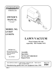
MANUFACTURING QUALITY LAWN CARE EQUIPMENT SINCE 1945
Owner’s
Manual
10 Cubic Foot
Dump Cart
FC-10
IMPORTANT
Read and follow all
Safety Precautions
and Instructions
Before Operating this
Equipment.
Made In CHINA
1602 CORPORATE DRIVE PO BOX 67 WARRENSBURG, MISSOURI 64093
PH 660. 747. 8183 FAX 660. 747. 8650
swisherinc.com
11765
REV. 05-339
LIMITED WARRANTY
The manufacturer’s warranty to the original consumer purchaser is: This product is free
from defects in materials and workmanship for a period of One (1) year from the date of
purchase by the original consumer purchaser. We will repair or replace, at our discretion,
parts found to be defective due to materials or workmanship. This warranty is subject to the
following limitations and exclusions:
1) Commercial Use
This product is not intended for commercial use and
carries no commercial warranty.
2) Limitation
This warranty applies only to products which have been
properly assembled, adjusted, and operated in accordance
with the instructions contained within this manual. This
warranty does not apply to any product of Swisher Mower
Co., Inc., that has been subject to alteration, misuse, abuse,
improper assembly or installation, shipping damage, or to
normal wear of the product.
3) Exclusions
Excluded from this warranty are normal wear, normal
adjustments, and normal maintenance.
In the event you have a claim under this warranty, you must return the product to an
authorized service dealer. All transportation charges, damage, or loss incurred during
transportation of parts submitted for replacement or repair under this warranty shall be borne
by the purchaser. Should you have any questions concerning this warranty, please contact
us toll-free at 1-800-222-8183. The model number, serial number, date of purchase, and the
name of the authorized Swisher dealer from whom you purchased the mower will be needed
before any warranty claim can be processed.
THIS WARRANTY DOES NOT APPLY TO ANY INCIDENTAL OR CONSEQUENTIAL
DAMAGES AND ANY IMPLIED WARRANTIES ARE LIMITED TO THE SAME TIME
PERIODS STATED HEREIN FOR ALL EXPRESSED WARRANTIES. Some states do not
allow the limitation of consequential damages or limitations on how long an implied warranty
may last, so the above limitations or exclusions may not apply to you. This warranty gives
you specific legal rights and you may have other rights, which vary from state-to-state. This is
a limited warranty as defined by the Magnuson-Moss Act of 1975.
2
Pre-Assembly Instructions
For easy assembly, follow all directions step by step.
Open all boxes before beginning to assemble. Approximate assembly time is: 1.5 to 3 hours
Helpful TIP: Read all instructions before starting to assemble cart.
Check Parts and Hardware:
Group together and check that all hardware and parts are included. Refer to listing and illustration below. If
you are missing parts please call Swisher Customer Service 1-800-222-8183 for assistance.
Tools Required:
Tape Measure
Flat Head Screwdriver (large size)
Standard Pliers
Two 10mm combination or ratchet style wrenches
Two 13 mm combination or ratchet style wrenches
Part Number Listing
Ref #
1
2
3
4
5
6
7
8
9
10
11
12
13
14
15
16
17
18
19
20
Hardware
21
22
23
24
25
26
27
28
29
30
31
32
Part #
Description
12166
12167
12168
12169
12170
12171
12172
12173
12174
12175
12176
12177
12178
12179
12180
12181
12182
12183
12184
12185
Bottom Panel
Front Cross Brace
Tongue Support
Wheel Axle Support
Axle
Wheel / Tire Assembly
Latch Spring
Latch Spacer
Tongue Latch
Hitch Tongue
Hitch Pin Bracket
Rear Cross Brace
Rear Corner Bracket
Side Panel
Rear Corner Brace
Front Panel
Front Corner Brace
Tailgate Latch
Tailgate Pin
Tailgate
12186
12187
NB275
NB718
NB719
NB195
NB603
12188
12189
12190
NB600
NB274
M8 X 16 Truss Head Bolt
M8 X 20 Truss Head Bolt
8mm Lock Washer
8mm Hex Nut
M8 X 20 Hex Head Bolt
20mm Flat Washer
3mm Cotter Pin
12.5 X 64 Hitch Pin
M6 X 90 Hex Head Bolt
6mm Nylon Nut
6mm Hex Nut
Flat Washer
Qty
2
1
1
2
1
2
1
2
1
1
1
1
2
2
2
1
2
2
2
1
60
2
72
72
10
2
3
1
1
1
2
2
Page 3
Complete Parts Illustration
for
Trailer Cart
Page 4
Step 1: Attaching Front Cross Brace
Position the two Bottom Panels(#1) as shown in Figure 1 below.
Attach the Front Cross Brace(#2) to the Bottom Panels using 4 (#21)
Bolts, 4 (#23) Washers, and 4 (#24) Nuts.
Hardware Needed for Step 1:
1 (#2) Cross Brace
4 (#21) Bolts
4 (#23) Washers
4 (#24) Nuts
2 (#1) Bottom Panels
Step 2: Connecting Bottom Panels
Attach Bottom Panels(#1) as shown in Figure 2, using 2 (#21) Bolts,
2(#23) Washers, and 2 (#24) Nuts. SKIP the two middle bolt
connections until Step #5, when attaching the Wheel Axle Support.
Hardware Needed for Step 2:
2 (#1) Bottom Panels
2 (#21) Bolts
2 (#23) Washers
2 (#24) Nuts
Page 5
Step 3: Attaching the Tongue Support
Attach the Tongue Support(#3) to the Bottom Panels as shown in Figure 3 using 2
(#22) Bolts, 2 (#23) Washers, and 2 (#24) Nuts.
Hardware Needed for Step 3:
2 (#22) Bolts
2 (#24) Nuts 2 (#23) Washers
2 (#23) Washers
Step 4: Assemble Wheel Axle Supports
As shown in Figure 4 below, connect together the 2 Wheel Axle
Supports (#4) using 8 (#25) Bolts, 8 (#23) Washers, and 8 (#24) Nuts.
DO NOT TIGHTEN BOLTS—leave bolts very loose for inserting axle
and tongue in Step #6.
Hardware Needed for Step 4:
2 (#4) Wheel Axle Supports
8 (#25) Bolts
8 (#23) Washers
8 (#24) Nuts
Page 6
Step 5: Attaching Wheel Axle Supports
To Bottom Panels
Attach Wheel Axle Supports (#4) to the Bottom Panels as
shown in Figure 5 to the right, using 4 (#21) Bolts per side.
Next, finish bolting together two middle connections of Bottom
Panels after Wheel Axle Support is in place. Using 2 (#21) Bolts,
2 (#23) Washers, and 2 (#24) Nuts.
Hardware Needed for Step 5:
2 (#4) Wheel Axle Supports (connected)
10 (#21) Bolts
10 (#23) Washers
10 (#24) Nuts
Step 6: Attaching Wheel Axle and Tires
Set Hitch Tongue(#10) in place as shown below before inserting
Wheel Axle(#5) through Wheel Axle Support(#4). Next, insert the
Wheel Axle (#5) into the Wheel Axle Support(#4), and through the
holes in the Tongue(#10) as shown in Figure 6. Be sure equal
amounts of axle extend from each side of Wheel Support.
TIGHTEN BOLTS ON WHEEL AXLE
SUPPORT.
Next, install each Tire Assembly (#6) onto
Wheel Axle, followed by a Washer(#26)
and a Cotter Pin(#27)
Hardware Needed for Step 6:
1 (#10) Hitch Tongue
1 (#5) Wheel Axle
2 (#6) Wheel Assemblies (Tires)
2 (#26) Washers
2 (#27) Cotter Pins
Step 7: Assembling Tongue Latch
Insert the Tongue Latch(#9) up through the opening in
the Hitch Tongue(#10). Place one Latch Spacer(#8)
on each side of the Tongue Latch(#9), the insert
Bolt(#29) to connect Hitch Tongue(#10) and Latch
Spacers(#8) and Tongue Latch(#9). Only Hand
Tighten (#29) Bolt to (#30) Nut. See Figure 7.
Next, attach one end of Latch Spring(#7) to Hitch
Tongue(#10) and one end of Latch Spring(#7) to top
hole in Tongue Latch(#9). Note hole locations from
Figure 7. Now completely tighten (#29) Bolt and (#30)
Nut.
Hardware Needed for Step 7:
1 (#9) Tongue Latch
2 (#8) Latch Spacers
1 (#7) Latch Spring
1 (#29) Bolt
1 (#30) Nut
Page 7
Step 8: Installing the Hitch Pin Bracket
Install the Hitch Pin Bracket(#11) in the back two holes of
the Hitch Tongue(#10) using 2 (#25) Bolts, 2 (#23) Washers,
and 2(#24) Nuts. Refer to Figure 8. Place Hitch
Pin(#28) in the front hole, using Cotter Pin(#27) to hold in
place.
Hardware Needed for Step 8:
1 (#11) Hitch Pin Bracket
2 (#25) Bolts
2 (#23) Washers
2 (#24) Nuts
1 (#28) Hitch Pin
1 (#27) Cotter Pin
Step 9: Installing the Rear Cross Brace
Turn the Trailer Cart over onto its wheels. Attach the Rear
Corner Brackets(#13) and the Rear Cross Brace(#12) to the
back of the Bottom Panels as shown in Figure 9. Use 2 (#21)
Bolts, 2 (#23)Washers, and 2 (#24) Nuts for each side.
Hardware Needed for Step 9:
1 (#12) Rear Cross Brace
2 (#13) Corner Brackets
4 (#21) Bolts
4 (#23) Washers
4 (#24) Nuts
Step 10: Side Panel Installation
Attach the Left Side Panel(#14) to the Bottom Panels as
shown in Figure 10 using 2 (#21) Bolts, 2 (#23) Washers, and
2 (#24) Nuts. Note bolt locations.
Hardware Needed for Step 10:
1 (#14) Side Panel
2 (#21) Bolts
2 (#23) Washers
2 (#24) Nuts
Page 8
Step 11: Secure Rear Cross Brace
Bolt Rear Cross Brace(#12) to Bottom
Panels(#1) using 6 (#21) Bolts, 6 (#23) Washers,
and 6 (#24) Nuts.
See Figure 11 for bolt locations.
Hardware Needed for Step 11:
6 (#21) Bolts
6 (#23) Washers
6 (#24) Nuts
Step 12: Side Panel Installation
Attach the Right Side Panel(#14) to the Bottom Panels as
shown in Figure 12 using 2 (#21) Bolts, 2 (#23) Washers, and
2 (#24) Nuts. Note bolt locations for side panel.
Hardware Needed for Step 12:
1 (#14) Side Panel
2 (#21) Bolts
2 (#23) Washers
2 (#24) Nuts
Step 13: Secure Side Panels
Secure each side panel by bolting a Rear Corner Brace(#15)
to the outside of the Side Panel(#14) using 5 (#21) Bolts, 5
(#23) Washers, and 5 (#24) Nuts per side. Figure 13 shows
left Rear Corner Bracket being attached.
Attach right side the same way.
Hardware Needed for Step 13:
2 (#15) Rear Corner Braces
10 (#21) Bolts
10 (#23) Washers
10 (#24) Nuts
Page 9
Step 14: Attach Front Panel
Attach the Front Panel(#16) to the Front Cross Brace(#2) and
to the two Side Panels(#14) using 12 (#21) Bolts, 12 (#23)
Washers, and 12 (#24) Nuts. See Figure 14 for bolt locations.
Hardware Needed for Step 14:
1 (#16) Front Panel
12 (#21) Bolts
12 (#23) Washers
12 (#24) Nuts
Step 15: Install Front Corner Braces
Install the Front Corner Braces(#17) to the corners of the Front
Panel(#16) and the Side Panels(#14) using 2 (#21) Bolts, 2
(#23) Washers, and 2 (#24) Nuts for each Front Corner Brace.
See Figure 15.
Hardware Needed for Step 15:
2 (#17) Front Corner Braces
4 (#21) Bolts
4 (#23) Washers
4 (#24) Nuts
Final Step: Attaching Tail Gate with Latches
First attach the two Tailgate Latches(#18) to the inside of the
Tailgate(#20) using 2 (#21) Bolts, 2 (#23) Washers, and 2
(#24) Nuts for each Tailgate Latch(#18). Next, insert the
Tailgate Pins(#19) into the holes on the bottom part of the
Tailgate. See Figure 16 for Tailgate Pin locations. Secure
Tailgate Pin(#19) by adding a (#32) Washer and a (#31) Nut to
the Pin threads.
Next, put Tailgate in place on the Trailer Cart. Position
Tailgate so the two Tailgate pins line up with the two holes on
the Rear Cross Brace(#12). The Tailgate latches can be
dropped over the open slots on the Side Panels that lock the
Tailgate into place. Assembly is complete.
Before using the cart,
check that all hardware connections are tight.
Hardware Needed for Step 16:
1 (#20) Tailgate
2 (#18) Tailgate Latches
2 (#19) Tailgate Pins
2 (#32) Washers
2 (#31) Nuts
4 (#21) Bolts
4 (#23) Washers
4 (#24) Nuts
Page 10
Operation/Maintenance NOTES:
Operation notesA full capacity load is 500 pounds, DO NOT exceed rated capacity.
Cart only to be used with lawn tractor or ATV.
Cart is not to for highway use.
Do not exceed 10mph when towing.
Maintenance notesOn a regular basis, check that tires are inflated properly. Pressure should be approx. 14psi.
NEVER over-inflate tires, ALWAYS check pressure max. on the tire.
Grease axle and wheel bearing area regularly or when needed.
Dry off cart after using in wet conditions.
MANUFACTURING QUALITY LAWN CARE EQUIPMENT SINCE 1945
Owner’s
Manual
FC-10
ATV & LAWN ACCESSORIES
WHEN ORDERING PARTS, PLEASE HAVE THE
FOLLOWING INORMATION AVAILABLE:
* PRODUCT – ________________
* SERIAL NUMBER - _______________
* MODEL NUMBER - _______________
TYPE - _______________
* PART NUMBER WITH PAINT CODE
* PART DESCRIPTION
TELEPHONE - 1-800-222-8183
FAX - 1-660-747-8650
IMPORTANT
Read and follow all
Safety Precautions
and Instructions
Before Operating this
Equipment.
SWISHER MOWER & MACHINE CO. INC.
1602 CORPORATE DRIVE
P.O. BOX 67
WARRENSBURG, MO 64093
swisherinc.com