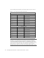
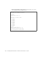
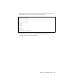
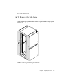
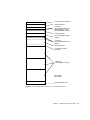
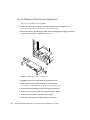
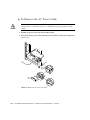
1
Sun StorEdge™ 3900 and 6900
Series 1.1 Reference and
Service Manual
Sun Microsystems, Inc.
4150 Network Circle
Santa Clara, CA 95054 U.S.A.
650-960-1300
Part No. 816-5253-10
July 2002, Revision A
Send comments about this document to: [email protected]
Copyright 2002 Sun Microsystems, Inc., 4150 Network Circle, Santa Clara, California 95054, U.S.A. All rights reserved.
Sun Microsystems, Inc. has intellectual property rights relating to technology embodied in the product that is described in this document. In
particular, and without limitation, these intellectual property rights may include one or more of the U.S. patents listed at
http://www.sun.com/patents and one or more additional patents or pending patent applications in the U.S. and in other countries.
This document and the product to which it pertains are distributed under licenses restricting their use, copying, distribution, and
decompilation. No part of the product or of this document may be reproduced in any form by any means without prior written authorization of
Sun and its licensors, if any.
Third-party software, including font technology, is copyrighted and licensed from Sun suppliers.
Parts of the product may be derived from Berkeley BSD systems, licensed from the University of California. UNIX is a registered trademark in
the U.S. and in other countries, exclusively licensed through X/Open Company, Ltd.
Sun, Sun Microsystems, the Sun logo, AnswerBook2, Sun StorEdge, StorTools, docs.sun.com, Sun Enterprise, Sun Fire, SunOS, Netra, SunSolve
and Solaris are trademarks, registered trademarks, or service marks of Sun Microsystems, Inc. in the U.S. and other countries. All SPARC
trademarks are used under license and are trademarks or registered trademarks of SPARC International, Inc. in the U.S. and other countries.
Products bearing SPARC trademarks are based upon an architecture developed by Sun Microsystems, Inc.
All SPARC trademarks are used under license and are trademarks or registered trademarks of SPARC International, Inc. in the U.S. and in other
countries. Products bearing SPARC trademarks are based upon an architecture developed by Sun Microsystems, Inc.
The OPEN LOOK and Sun™ Graphical User Interface was developed by Sun Microsystems, Inc. for its users and licensees. Sun acknowledges
the pioneering efforts of Xerox in researching and developing the concept of visual or graphical user interfaces for the computer industry. Sun
holds a non-exclusive license from Xerox to the Xerox Graphical User Interface, which license also covers Sun’s licensees who implement OPEN
LOOK GUIs and otherwise comply with Sun’s written license agreements.
Use, duplication, or disclosure by the U.S. Government is subject to restrictions set forth in the Sun Microsystems, Inc. license agreements and as
provided in DFARS 227.7202-1(a) and 227.7202-3(a) (1995), DFARS 252.227-7013(c)(1)(ii) (Oct. 1998), FAR 12.212(a) (1995), FAR 52.227-19, or
FAR 52.227-14 (ALT III), as applicable.
DOCUMENTATION IS PROVIDED "AS IS" AND ALL EXPRESS OR IMPLIED CONDITIONS, REPRESENTATIONS AND WARRANTIES,
INCLUDING ANY IMPLIED WARRANTY OF MERCHANTABILITY, FITNESS FOR A PARTICULAR PURPOSE OR NON-INFRINGEMENT,
ARE DISCLAIMED, EXCEPT TO THE EXTENT THAT SUCH DISCLAIMERS ARE HELD TO BE LEGALLY INVALID.
Copyright 2002 Sun Microsystems, Inc., 4150 Network Circle, Santa Clara, California 95054, Etats-Unis. Tous droits réservés.
Sun Microsystems, Inc. a les droits de propriété intellectuels relatants à la technologie incorporée dans le produit qui est décrit dans ce
document. En particulier, et sans la limitation, ces droits de propriété intellectuels peuvent inclure un ou plus des brevets américains énumérés
à http://www.sun.com/patents et un ou les brevets plus supplémentaires ou les applications de brevet en attente dans les Etats-Unis et dans
les autres pays.
Ce produit ou document est protégé par un copyright et distribué avec des licences qui en restreignent l’utilisation, la copie, la distribution, et la
décompilation. Aucune partie de ce produit ou document ne peut être reproduite sous aucune forme, parquelque moyen que ce soit, sans
l’autorisation préalable et écrite de Sun et de ses bailleurs de licence, s’il y ena.
Le logiciel détenu par des tiers, et qui comprend la technologie relative aux polices de caractères, est protégé par un copyright et licencié par des
fournisseurs de Sun.
Des parties de ce produit pourront être dérivées des systèmes Berkeley BSD licenciés par l’Université de Californie. UNIX est une marque
déposée aux Etats-Unis et dans d’autres pays et licenciée exclusivement par X/Open Company, Ltd.
Sun, Sun Microsystems, le logo Sun, AnswerBook2, Sun StorEdge, StorTools, docs.sun.com, Sun Enterprise, Sun Fire, SunOS, Netra, SunSolve,
et Solaris sont des marques de fabrique ou des marques déposées, ou marques de service, de Sun Microsystems, Inc. aux Etats-Unis et dans
d’autres pays. Toutes les marques SPARC sont utilisées sous licence et sont des marques de fabrique ou des marques déposées de SPARC
International, Inc. aux Etats-Unis et dans d’autres pays. Les produits portant les marques SPARC sont basés sur une architecture développée
par Sun Microsystems, Inc.
Toutes les marques SPARC sont utilisées sous licence et sont des marques de fabrique ou des marques déposées de SPARC International, Inc.
aux Etats-Unis et dans d’autres pays. Les produits protant les marques SPARC sont basés sur une architecture développée par Sun
Microsystems, Inc.
L’interface d’utilisation graphique OPEN LOOK et Sun™ a été développée par Sun Microsystems, Inc. pour ses utilisateurs et licenciés. Sun
reconnaît les efforts de pionniers de Xerox pour la recherche et le développment du concept des interfaces d’utilisation visuelle ou graphique
pour l’industrie de l’informatique. Sun détient une license non exclusive do Xerox sur l’interface d’utilisation graphique Xerox, cette licence
couvrant également les licenciées de Sun qui mettent en place l’interface d ’utilisation graphique OPEN LOOK et qui en outre se conforment
aux licences écrites de Sun.
LA DOCUMENTATION EST FOURNIE "EN L’ÉTAT" ET TOUTES AUTRES CONDITIONS, DECLARATIONS ET GARANTIES EXPRESSES
OU TACITES SONT FORMELLEMENT EXCLUES, DANS LA MESURE AUTORISEE PAR LA LOI APPLICABLE, Y COMPRIS NOTAMMENT
TOUTE GARANTIE IMPLICITE RELATIVE A LA QUALITE MARCHANDE, A L’APTITUDE A UNE UTILISATION PARTICULIERE OU A
L’ABSENCE DE CONTREFAÇON.
Please
Recycle
Contents
Preface
1.
Introduction
1.1
2.
xxiii
1-1
Overview
1-1
1.1.1
Sun StorEdge 3910 System
1-3
1.1.2
Sun StorEdge 3960 System
1-4
1.1.3
Sun StorEdge 6910 System
1-5
1.1.4
Sun StorEdge 6960 System
1-6
1.1.5
Sun StorEdge 3900 and 6900 Series Switchless Systems
1.2
Architecture
1.3
System-Level Support Information
1.4
Features
1-8
1-10
1-10
1.4.1
Sun StorEdge 3900 and 6900 Series Common Features
1.4.2
Sun StorEdge 3900 Series Features
1.4.3
Additional Sun StorEdge 6900 Series Features
Component Descriptions
2.1
1-7
1-11
1-13
1-13
2-1
Hardware Descriptions
2-1
2.1.1
Storage Service Processor
2-2
2.1.2
Virtualization Engines
2.1.3
Customer Management Connection
2-2
2-3
Contents
iii
2.2
3.
2.1.4
Storage Devices
2.1.5
Ethernet Hub
2.1.6
Fibre Channel Switches
2.1.7
Sun StorEdge Expansion Cabinet
Software Descriptions
5.
iv
2-4
2-4
2-5
2-5
2.2.1
Solaris 8
2.2.2
Sun StorEdge Remote Response
2.2.3
Configuration Utilities
2.2.4
Storage Automated Diagnostic Environment
2-6
2-6
2-6
2-7
2.2.4.1
Diagnostics
2-7
2.2.4.2
Storage Automated Diagnostic Environment Agent
2-7
2.2.4.3
Configuration User Interface
2.2.5
SANSurfer
2.2.6
Sun StorEdge SAN 4.0 Release Support
2-8
2-10
Default Configurations and Settings
2-10
3-1
3.1
Sun StorEdge 3900 and 6900 Series Layout
3.2
Virtualization Engine Settings
3.3
Sun StorEdge T3+ Array Settings
3.3.1
4.
2-3
3-2
3-4
3-9
Sun StorEdge T3+ Array Partner Group syslog.conf
Configuration 3-12
3.4
Sun StorEdge Network FC Switch Settings
3.5
Ethernet Address Settings
Configuration Features
3-12
3-19
4-1
4.1
Standalone With No Remote Service
4.2
Multiple Units With No Remote Service
4.3
Remote Service to a Single Unit With No Host Connection
4.4
Remote Service to Multiple Units With No Host Connection
Configuration Utilities
4-1
4-2
5-1
Sun StorEdge 3900 and 6900 Series 1.1 Reference and Service Manual • July 2002
4-3
4-4
5.1
Overview
5.2
Menu-Driven Character User Interface
5.3
6.
7.
5-1
5.2.1
Sun StorEdge T3+ Array Configuration Utility Main Menu
5.2.2
Sun StorEdge Network FC Switch Main Menu
5.2.3
Virtualization Engine Main Menu
5.2.4
View Log Option
5.2.5
View Errors Option
Command Line Interface
5-3
5-20
5-30
5-46
5-47
5-48
5.3.1
Storage Service Processor Global Commands
5.3.2
Storage Service Processor Sun StorEdge T3+ Array Commands
5-49
5.3.3
Storage Service Processor Switch Commands
5.3.4
Storage Service Processor Virtualization Engine Commands
Fault Detection and Isolation Overview
6.1
Monitoring
6.2
Fault Detection
5-48
5-51
5-53
6-1
6-1
6-2
6.2.1
Local Monitoring
6.2.2
Remote Monitoring
6.3
Fault Isolation
6.4
Security
6-2
6-3
6-3
6-4
Preparing for Service
7-1
7.1
Safety Requirements
7.2
Removing and Replacing the Front Door
7.3
5-2
7-1
▼
To Remove the Front Door
7-2
▼
To Replace the Front Door
7-2
Removing and Replacing the Side Panel
7-2
7-2
▼
To Remove the Side Panel
7-3
▼
To Replace the Side Panel
7-4
▼
To Open the Back Door of the Storage System
7-4
Contents
v
8.
Installing and Removing FRUs
8.1
Safety Requirements
8.2
FRU Placement
8.3
Installing a FRU
▼
8.4
9.
10.
8-7
10.3
10.4
10.5
To Remove a FRU
8-10
9-1
▼
To Remove the Ethernet Hub
9-1
▼
To Replace the Ethernet Hub
9-3
10-1
Servicing the Power Sequencer
10-1
▼
To Remove the Power Sequencer
10-2
▼
To Replace the Power Sequencer
10-3
Servicing the AC Power Cable
10-3
▼
To Remove the AC Power Cable
10-4
▼
To Replace the AC Power Cable
10-5
Servicing the Key Switch
10-5
▼
To Remove the Key Switch
10-6
▼
To Replace the Key Switch
10-7
Servicing the Fan Tray
10-8
▼
To Remove the Fan Tray
10-8
▼
To Replace the Fan Tray
10-8
Adding a Cabinet in the Field
▼
10-9
11-1
Service Panel Overview
▼
10-9
To Add a Cabinet in the Field
Servicing the Service Panel
11.1
8-7
8-10
Servicing the Expansion Cabinet
10.2
vi
8-3
Servicing the Ethernet Hub
10.1
11.
8-1
To Open the System to Access a FRU
Removing a FRU
▼
8-1
11-1
To Remove the Service Panel
11-5
Sun StorEdge 3900 and 6900 Series 1.1 Reference and Service Manual • July 2002
▼
12.
11-6
Servicing the Storage Service Processor
12-1
12.1
Preliminary Steps
12.2
Connecting to the Storage Service Processor
12.3
12.4
12.5
13.
To Replace the Service Panel
12-2
12-2
▼
To Connect an External Serial Terminal to the Storage Service
Processor 12-2
▼
To Gain Access to the Serial Port of the Storage Service Processor
▼
To Make an Ethernet Terminal Connection
▼
To Make an Ethernet Connection to the Console Port of the Storage
Service Processor 12-6
12-3
12-5
Servicing the Storage Service Processor With the Sun StorEdge Remote
Response Enabled 12-7
▼
To Connect to the Storage Service Processor
12-8
▼
To Remove the Storage Service Processor
12-9
▼
To Replace the Storage Service Processor
12-10
Servicing the Storage Service Processor Without the Sun StorEdge Remote
Response Enabled 12-12
▼
To Connect to the Storage Service Processor
▼
To Remove the Storage Service Processor
▼
To Replace the Storage Service Processor Without the Remote Response
Enabled 12-14
Replacing the Storage Service Processor
12-12
12-13
12-16
Servicing the Sun StorEdge Network FC Switch-8 and Switch-16
Switches 13-1
13.1
13.2
Servicing the FC Switch
13-2
▼
To Remove the FC Switch
13-2
▼
To Replace the FC Switch
13-3
▼
To Upgrade the Sun StorEdge Network FC Switch Firmware
13-5
Upgrading to Use Sun StorEdge SAN 4.0 Release Switches from Solaris
Servers 13-5
Contents
vii
13.3
▼
To Convert a Sun StorEdge 3900 or 6900 Series to Sun StorEdge SAN 4.0
Release 13-6
▼
To Obtain the Sun StorEdge SAN 4.0 Release Switch Firmware
Upgrading and Downgrading for 1 Gbit Switch
▼
14.
15.
16.
13-7
14-1
▼
To Remove a Sun StorEdge T3+ Array
14-2
▼
To Replace a Sun StorEdge T3+ Array
14-3
▼
To Add a Sun StorEdge T3+ Array
▼
To Upgrade the Sun StorEdge T3+ Array Firmware
Servicing the Virtualization Engines
14-5
14-7
15-1
▼
To Remove a Virtualization Engine
15-2
▼
To Replace a Virtualization Engine
15-2
▼
To Upgrade the Virtualization Engine Firmware
▼
To Replace the HBAs
15-5
15-6
Servicing the Network Terminal Concentrator
16-1
16.1
Overview
16-2
16.2
Removing and Replacing the Sun StorEdge Remote Response Hardware
16-3
▼
To Remove the NTC Unit
16-3
▼
To Replace the NTC Unit
16-4
A. System Part Numbers
11
A.1
Sun Field-Replaceable Units
A.2
Sun StorEdge Storage Systems
A.2.1
A.3
viii
13-7
To Upgrade and Downgrade for a 1 Gbit Switch
Servicing Sun StorEdge T3+ Arrays
13-6
11
13
Explanation of an Example Part Number TB3910-B2-1321 15
Cable Part Numbers
16
Sun StorEdge 3900 and 6900 Series 1.1 Reference and Service Manual • July 2002
Figures
FIGURE 1-1
Sun StorEdge 3910 System
1-3
FIGURE 1-2
Sun StorEdge 3960 System
1-4
FIGURE 1-3
Sun StorEdge 6910 System
1-5
FIGURE 1-4
Sun StorEdge 6960 System
1-6
FIGURE 1-5
Basic Sun StorEdge 3900 Series Architecture 1-8
FIGURE 1-6
Basic Sun StorEdge 6900 Series Architecture 1-9
FIGURE 2-1
Configuration Utilities User Interface
FIGURE 3-1
BackView of the Sun StorEdge 3960 System 3-2
FIGURE 3-2
Back View of the Sun StorEdge 6960 System 3-3
FIGURE 4-1
Multiple Units Without the Sun StorEdge Remote Response Option
FIGURE 4-2
Remote Service to a Single Unit With No Host 4-3
FIGURE 4-3
Remote Service to Multiple Units With No Host Connection 4-5
FIGURE 7-1
Removing and Replacing the Side Panels
FIGURE 7-2
Opening the Back Door of the Storage System 7-4
FIGURE 8-1
Sun StorEdge 3910 Storage System FRU Placement
FIGURE 8-2
Sun StorEdge 3960 and 3900SL System FRU Placement 8-4
FIGURE 8-3
Sun StorEdge 6910 and 6910SL System FRU Placement 8-5
FIGURE 8-4
Sun StorEdge 6960 and 6960SL System FRU Placement 8-6
FIGURE 8-5
Filler Panel and Trim Strip Location 8-8
FIGURE 8-6
Power Cable Routing 8-9
2-9
4-2
7-3
8-3
ix
x
FIGURE 10-1
Removing the Power Sequencer 10-2
FIGURE 10-2
Removing the AC Power Cable 10-4
FIGURE 10-3
Key Switch Cable Connector 10-6
FIGURE 10-4
Removing and Replacing the Key Switch
FIGURE 11-1
Storage Service Processor Service Panel Connections 11-2
FIGURE 16-1
Securing the NTC to the NTC Mount 16-4
10-7
Sun StorEdge 3900 and 6900 Series 1.1 Reference and Service Manual • July 2002
Tables
TABLE 1-1
Sun StorEdge 3900 and 6900 Series System-Level Configurations 1-10
TABLE 3-1
Standard Virtualization Engine Settings
TABLE 3-2
Virtualization Engine Names
TABLE 3-3
Sun StorEdge 6910 and 6910SL System Defaults 3-5
TABLE 3-4
Sun StorEdge 6960 and 6960SL System Defaults 3-6
TABLE 3-5
Sun StorEdge 6910 and 6910SL System Defaults for 181-Gbyte Drives 3-7
TABLE 3-6
Sun StorEdge 6960 and 6960SL System Defaults for 181-Gbyte Drives 3-7
TABLE 3-7
Sun StorEdge T3+ Array Configuration Types 3-9
TABLE 3-8
Sun StorEdge T3+ Array Partner Group Target IDs and Host Names 3-10
TABLE 3-9
Sun StorEdge T3+ Array Partner Group Set Command Configuration Settings
TABLE 3-10
Sun StorEdge T3+ Array Partner Group System List Command Configuration Settings
TABLE 3-11
Sun StorEdge T3+ Array Partner Group Miscellaneous Configuration Parameters 3-11
TABLE 3-12
Sun StorEdge Network FC Switch-8 and Switch-16 Switch Parameters 3-13
TABLE 3-13
Sun StorEdge 3910 System Switch Configuration 3-14
TABLE 3-14
Sun StorEdge 3960 System Switch Configuration 3-15
TABLE 3-15
Sun StorEdge 6910 System Switch Configuration 3-16
TABLE 3-16
Sun StorEdge 6910 and 6910SL System Configuration 3-16
TABLE 3-17
Sun StorEdge 6960 System Configuration 3-17
TABLE 3-18
Sun StorEdge 6910 and 6960SL System Switch Configuration 3-18
TABLE 3-19
Ethernet Addressing Configurations
3-4
3-5
3-10
3-11
3-19
xi
xii
TABLE 9-1
Ethernet Hub FRU List 9-1
TABLE 10-1
Sun StorEdge Expansion Cabinet FRU List
TABLE 10-2
AC Power Cable FRU List 10-3
TABLE 10-3
Key Switch FRU List
TABLE 10-4
Fan Tray FRU List 10-8
TABLE 11-1
Service Processor Service Panel FRU List 11-1
TABLE 11-2
Storage Service Processor to Service Panel Cabling 11-3
TABLE 11-3
Service Panel Connectors
TABLE 12-1
Storage Service Processor FRU List
TABLE 13-1
Sun StorEdge Network FC Switch-8 and Switch-16 FRU List
TABLE 14-1
Sun StorEdge T3+ Array Partner Group FRU list 14-1
TABLE 15-1
Virtualization Engine FRU List
TABLE 16-1
Network Terminal Concentrator FRU List 16-1
TABLE 16-2
Sun StorEdge Remote Response Program Service Panel Cabling
TABLE A-1
FRU List 11
TABLE A-2
Sun StorEdge 3900 and 6900 Series Storage Systems Part Numbers 13
TABLE A-3
Explanation of the Content of the Storage System Part Numbers
TABLE A-4
Fiber Optic FRU Cable Replacement Part Numbers 16
TABLE A-5
Ethernet FRU Cable Replacement Part Numbers 17
10-1
10-5
11-4
12-1
13-1
15-1
Sun StorEdge 3900 and 6900 Series 1.1 Reference and Service Manual • July 2002
16-3
15
Safety Agency Compliance
Statements
Depending on the type of power switch your device has,
one of the following symbols may be used:
Off - Removes AC power from the system.
Read this section before beginning any procedure. The
following text provides safety precautions to follow when
installing a Sun Microsystems product.
Safety Precautions
Standby – The On/Standby switch is in the
standby position.
For your protection, observe the following safety
precautions when setting up your equipment:
■
■
■
Follow all cautions and instructions marked on the
equipment.
Ensure that the voltage and frequency of your power
source match the voltage and frequency inscribed on
the equipment’s electrical rating label.
Never push objects of any kind through openings in
the equipment. Dangerous voltages may be present.
Conductive foreign objects could produce a short
circuit that could cause fire, electric shock, or damage
to your equipment.
Symbols
The following symbols may appear in this book:
Modifications to Equipment
Do not make mechanical or electrical modifications to the
equipment. Sun Microsystems is not responsible for
regulatory compliance of a modified Sun product.
Placement of a Sun Product
Caution – Do not block or cover the openings
of your Sun product. Never place a Sun
product near a radiator or heat register.
Failure to follow these guidelines can cause
overheating and affect the reliability of your
Sun product.
Caution – There is risk of personal injury and
equipment damage. Follow the instructions.
Caution – The workplace-dependent noise
level defined in DIN 45 635 Part 1000 must be
70Db(A) or less.
Caution – Hot surface. Avoid contact.
Surfaces are hot and may cause personal
injury if touched.
Caution – Hazardous voltages are present. To
reduce the risk of electric shock and danger to
personal health, follow the instructions.
On – Applies AC power to the system.
xiii
SELV Compliance
Safety status of I/O connections comply to SELV
requirements.
Power Cord Connection
Caution – Sun products are designed to work
with single-phase power systems having a
grounded neutral conductor. To reduce the
risk of electric shock, do not plug Sun
products into any other type of power system.
Contact your facilities manager or a qualified
electrician if you are not sure what type of
power is supplied to your building.
Caution – Not all power cords have the same
current ratings. Household extension cords do
not have overload protection and are not
meant for use with computer systems. Do not
use household extension cords with your Sun
product.
Caution – Your Sun product is shipped with
a grounding type (three-wire) power cord. To
reduce the risk of electric shock, always plug
the cord into a grounded power outlet.
The following caution applies only to devices with a
Standby power switch:
Caution – The power switch of this product
functions as a standby type device only. The
power cord serves as the primary disconnect
device for the system. Be sure to plug the
power cord into a grounded power outlet that
is nearby the system and is readily accessible.
Do not connect the power cord when the
power supply has been removed from the
system chassis.
xiv
Lithium Battery
Caution – On Sun CPU boards, there is a
lithium battery molded into the real-time
clock, SGS No. MK48T59Y, MK48TXXB-XX,
MK48T18-XXXPCZ, M48T59W-XXXPCZ, or
MK48T08. Batteries are not customer
replaceable parts. They may explode if
mishandled. Do not dispose of the battery in
fire. Do not disassemble it or attempt to
recharge it.
Battery Pack
Caution – There is a sealed lead acid battery
in Sun StorEdge FC-AL Switch units. Portable
Energy Products No. TLC02V50. There is
danger of explosion if the battery pack is
mishandled or incorrectly replaced. Replace
only with the same type of Sun Microsystems
battery pack. Do not disassemble it or attempt
to recharge it outside the system. Do not
dispose of the battery in fire. Dispose of the
battery properly in accordance with local
regulations.
System Unit Cover
You must remove the cover of your Sun computer system
unit to add cards, memory, or internal storage devices. Be
sure to replace the top cover before powering on your
computer system.
Caution – Do not operate Sun products
without the top cover in place. Failure to take
this precaution may result in personal injury
and system damage.
Sun StorEdge 3900 and 6900 Series Version 1.1 Reference and Service Guide • July 2002
Laser Compliance Notice
Symbole
Sun products that use laser technology comply with Class 1
laser requirements.
Die Symbole in diesem Handbuch haben folgende
Bedeutung:
Achtung – Gefahr von Verletzung und
Class 1 Laser Product
Luokan 1 Laserlaite
Klasse 1 Laser Apparat
Laser KLasse 1
Geräteschaden. Befolgen Sie die
Anweisungen.
Achtung – Hohe Temperatur. Nicht
berühren, da Verletzungsgefahr durch heiße
Oberfläche besteht.
CD-ROM
Caution – Use of controls, adjustments, or
the performance of procedures other than
those specified herein may result in hazardous
radiation exposure.
Achtung – Gefährliche Spannungen.
Anweisungen befolgen, um Stromschläge und
Verletzungen zu vermeiden.
Ein – Setzt das System unter Wechselstrom.
Einhaltung sicherheitsbehördlicher
Vorschriften
Auf dieser Seite werden Sicherheitsrichtlinien beschrieben,
die bei der Installation von Sun-Produkten zu beachten
sind.
Sicherheitsvorkehrungen
Treffen Sie zu Ihrem eigenen Schutz die folgenden
Sicherheitsvorkehrungen, wenn Sie Ihr Gerät installieren:
■
■
■
Beachten Sie alle auf den Geräten angebrachten
Warnhinweise und Anweisungen.
Vergewissern Sie sich, daß Spannung und Frequenz
Ihrer Stromquelle mit der Spannung und Frequenz
übereinstimmen, die auf dem Etikett mit den
elektrischen Nennwerten des Geräts angegeben sind.
Stecken Sie auf keinen Fall irgendwelche Gegenstände
in Öffnungen in den Geräten. Leitfähige Gegenstände
könnten aufgrund der möglicherweise vorliegenden
gefährlichen Spannungen einen Kurzschluß
verursachen, der einen Brand, Stromschlag oder
Geräteschaden herbeiführen kann.
Je nach Netzschaltertyp an Ihrem Gerät kann eines der
folgenden Symbole benutzt werden:
Aus – Unterbricht die Wechselstromzufuhr
zum Gerät.
Wartezustand (Stand-by-Position) - Der Ein/Wartezustand-Schalter steht auf
Wartezustand. Änderungen an Sun-Geräten.
Nehmen Sie keine mechanischen oder elektrischen
Änderungen an den Geräten vor. Sun Microsystems,
übernimmt bei einem Sun-Produkt, das geändert wurde,
keine Verantwortung für die Einhaltung behördlicher
Vorschriften
xv
Aufstellung von Sun-Geräten
Die folgende Warnung gilt nur für Geräte mit
Wartezustand-Netzschalter:
Achtung – Um den zuverlässigen Betrieb
Ihres Sun-Geräts zu gewährleisten und es vor
Überhitzung zu schützen, dürfen die
Öffnungen im Gerät nicht blockiert oder
verdeckt werden. Sun-Produkte sollten
niemals in der Nähe von Heizkörpern oder
Heizluftklappen aufgestellt werden.
Achtung – Der arbeitsplatzbezogene
Schalldruckpegel nach DIN 45 635 Teil 1000
beträgt 70Db(A) oder weniger.
Achtung – Der Ein/Aus-Schalter dieses
Geräts schaltet nur auf Wartezustand (StandBy-Modus). Um die Stromzufuhr zum Gerät
vollständig zu unterbrechen, müssen Sie das
Netzkabel von der Steckdose abziehen.
Schließen Sie den Stecker des Netzkabels an
eine in der Nähe befindliche, frei zugängliche,
geerdete Netzsteckdose an. Schließen Sie das
Netzkabel nicht an, wenn das Netzteil aus der
Systemeinheit entfernt wurde.
Lithiumbatterie
Einhaltung der SELV-Richtlinien
Die Sicherung der I/O-Verbindungen entspricht den
Anforderungen der SELV-Spezifikation.
Anschluß des Netzkabels
Achtung – Sun-Produkte sind für den Betrieb
an Einphasen-Stromnetzen mit geerdetem
Nulleiter vorgesehen. Um die
Stromschlaggefahr zu reduzieren, schließen
Sie Sun-Produkte nicht an andere
Stromquellen an. Ihr Betriebsleiter oder ein
qualifizierter Elektriker kann Ihnen die Daten
zur Stromversorgung in Ihrem Gebäude
geben.
Achtung – CPU-Karten von Sun verfügen
über eine Echtzeituhr mit integrierter
Lithiumbatterie (Teile-Nr. MK48T59Y,
MK48TXXB-XX, MK48T18-XXXPCZ,
M48T59W-XXXPCZ, oder MK48T08). Diese
Batterie darf nur von einem qualifizierten
Servicetechniker ausgewechselt werden, da sie
bei falscher Handhabung explodieren kann.
Werfen Sie die Batterie nicht ins Feuer.
Versuchen Sie auf keinen Fall, die Batterie
auszubauen oder wiederaufzuladen.
Batterien
Achtung – Die Geräte Sun StorEdge FC-AL
Achtung – Nicht alle Netzkabel haben die
gleichen Nennwerte. Herkömmliche, im
Haushalt verwendete Verlängerungskabel
besitzen keinen Überlastungsschutz und sind
daher für Computersysteme nicht geeignet.
Achtung – Ihr Sun-Gerät wird mit einem
dreiadrigen Netzkabel für geerdete
Netzsteckdosen geliefert. Um die Gefahr eines
Stromschlags zu reduzieren, schließen Sie das
Kabel nur an eine fachgerecht verlegte,
geerdete Steckdose an.
xvi
Switch enthalten auslaufsichere
Bleiakkumulatoren. Produkt-Nr. TLC02V50
für portable Stromversorgung. Werden bei der
Behandlung oder beim Austausch der Batterie
Fehler gemacht, besteht Explosionsgefahr.
Batterie nur gegen Batterien gleichen Typs von
Sun Microsystems austauschen. Nicht
demontieren und nicht versuchen, die Batterie
außerhalb des Geräts zu laden. Batterie nicht
ins Feuer werfen. Ordnungsgemäß
entsprechend den vor Ort geltenden
Vorschriften entsorgen.
Sun StorEdge 3900 and 6900 Series Version 1.1 Reference and Service Guide • July 2002
Gehäuseabdeckung
Sie müssen die obere Abdeckung Ihres Sun-Systems
entfernen, um interne Komponenten wie Karten,
Speicherchips oder Massenspeicher hinzuzufügen. Bringen
Sie die obere Gehäuseabdeckung wieder an, bevor Sie Ihr
System einschalten.
■
Ne jamais introduire d’objets quels qu’ils soient dans
une des ouvertures de l’appareil. Vous pourriez vous
trouver en présence de hautes tensions dangereuses.
Tout objet conducteur introduit de la sorte pourrait
produire un court-circuit qui entraînerait des
flammes, des risques d’électrocution ou des dégâts
matériels.
Achtung – Bei Betrieb des Systems ohne
Symboles
obere Abdeckung besteht die Gefahr von
Stromschlag und Systemschäden.
Vous trouverez ci-dessous la signification des différents
symboles utilisés :
Einhaltung der Richtlinien für Laser
Sun-Produkte, die mit Laser-Technologie arbeiten,
entsprechen den Anforderungen der Laser Klasse 1.
Class 1 Laser Product
Luokan 1 Laserlaite
Klasse 1 Laser Apparat
Laser KLasse 1
CD-ROM
Attention: – risques de blessures corporelles
et de dégâts matériels. Veuillez suivre les
instructions.
Attention: – surface à température élevée.
Evitez le contact. La température des surfaces
est élevée et leur contact peut provoquer des
blessures corporelles.
Attention: – présence de tensions
dangereuses. Pour éviter les risques
d’électrocution et de danger pour la santé
physique, veuillez suivre les instructions.
Warnung – Die Verwendung von anderen
Steuerungen und Einstellungen oder die
Durchfhrung von Prozeduren, die von den
hier beschriebenen abweichen, knnen
gefhrliche Strahlungen zur Folge haben.
Conformité aux normes de sécurité
Ce texte traite des mesures de sécurité qu’il convient de
prendre pour l’installation d’un produit Sun Microsystems.
MARCHE – Votre système est sous tension
(courant alternatif).
Un des symboles suivants sera peut-être utilisé en fonction
du type d'interrupteur de votre système:
ARRET - Votre système est hors tension
(courant alternatif).
Mesures de sécurité
Pour votre protection, veuillez prendre les précautions
suivantes pendant l’installation du matériel :
■
■
Suivre tous les avertissements et toutes les
instructions inscrites sur le matériel.
Vérifier que la tension et la fréquence de la source
d’alimentation électrique correspondent à la tension et
à la fréquence indiquées sur l’étiquette de
classification de l’appareil.
VEILLEUSE – L'interrupteur Marche/
Veilleuse est en position « Veilleuse ».
xvii
Modification du matériel
Ne pas apporter de modification mécanique ou électrique
au matériel. Sun Microsystems n’est pas responsable de la
conformité réglementaire d’un produit Sun qui a été
modifié.
Positionnement d’un produit Sun
Attention: – pour assurer le bon
fonctionnement de votre produit Sun et pour
l’empêcher de surchauffer, il convient de ne
pas obstruer ni recouvrir les ouvertures
prévues dans l’appareil. Un produit Sun ne
doit jamais être placé à proximité d’un
radiateur ou d’une source de chaleur.
Attention: – Le niveau de pression
acoustique au poste de travail s'élève selon la
norme DIN 45 635 section 1000, à 70 dB (A) ou
moins.
Conformité SELV
Sécurité : les raccordements E/S sont conformes aux
normes SELV.
Connexion du cordon d’alimentation.
Attention: – les produits Sun sont conçus
pour fonctionner avec des alimentations
monophasées munies d’un conducteur neutre
mis à la terre. Pour écarter les risques
d’électrocution, ne pas brancher de produit
Sun dans un autre type d’alimentation secteur.
En cas de doute quant au type d’alimentation
électrique du local, veuillez vous adresser au
directeur de l’exploitation ou à un électricien
qualifié.
xviii
Attention: – tous les cordons d’alimentation
n’ont pas forcément la même puissance
nominale en matière de courant. Les rallonges
d’usage domestique n’offrent pas de
protection contre les surcharges et ne sont pas
prévues pour les systèmes d’ordinateurs. Ne
pas utiliser de rallonge d’usage domestique
avec votre produit Sun.
Attention: – votre produit Sun a été livré
équipé d’un cordon d’alimentation à trois fils
(avec prise de terre). Pour écarter tout risque
d’électrocution, branchez toujours ce cordon
dans une prise mise à la terre.
L'avertissement suivant s'applique uniquement aux
systèmes équipés d'un interrupteur VEILLEUSE:
Attention: – le commutateur d’alimentation
de ce produit fonctionne comme un dispositif
de mise en veille uniquement. C’est la prise
d’alimentation qui sert à mettre le produit
hors tension. Veillez donc à installer le produit
à proximité d’une prise murale facilement
accessible. Ne connectez pas la prise
d’alimentation lorsque le châssis du système
n’est plus alimenté.
Batterie au lithium
Attention: – sur les cartes CPU Sun, une
batterie au lithium (référence MK48T59Y,
MK48TXXB-XX, MK48T18-XXXPCZ,
M48T59W-XXXPCZ, ou MK48T08.) a été
moulée dans l’horloge temps réel SGS. Les
batteries ne sont pas des pièces remplaçables
par le client. Elles risquent d’exploser en cas
de mauvais traitement. Ne pas jeter la batterie
au feu. Ne pas la démonter ni tenter de la
recharger.
Sun StorEdge 3900 and 6900 Series Version 1.1 Reference and Service Guide • July 2002
Bloc-batterie
CD-ROM
Attention: – Les unités Sun StorEdge FC-AL
Switch contiennent une batterie étanche au
plomb (produits énergétiques portatifs
n˚TLC02V50). Il existe un risque d’explosion si
ce bloc-batterie est manipulé de façon erronée
ou mal mis en place. Ne remplacez ce bloc que
par un bloc-batterie Sun Microsystems du
même type. Ne le démontez pas et n’essayez
pas de le recharger hors du système. Ne faites
pas brûler la batterie mais mettez-la au rebut
conformément aux réglementations locales en
vigueur.
Attention: – L’utilisation de contrôles, de
réglages ou de performances de procédures
autre que celle spécifiée dans le présent
document peut provoquer une exposition à
des radiations dangereuses.
Normativas de seguridad
El siguiente texto incluye las medidas de seguridad que se
deben seguir cuando se instale algún producto de Sun
Microsystems.
Precauciones de seguridad
Couvercle
Pour ajouter des cartes, de la mémoire, ou des unités de
stockage internes, vous devrez démonter le couvercle de
l’unité système Sun. Ne pas oublier de remettre ce couvercle
en place avant de mettre le système sous tension.
Attention: – il est dangereux de faire
fonctionner un produit Sun sans le couvercle
en place. Si l’on néglige cette précaution, on
encourt des risques de blessures corporelles et
de dégâts matériels.
Conformité aux certifications Laser
Les produits Sun qui font appel aux technologies lasers sont
conformes aux normes de la classe 1 en la matière.
Class 1 Laser Product
Luokan 1 Laserlaite
Klasse 1 Laser Apparat
Laser KLasse 1
Para su protección observe las siguientes medidas de
seguridad cuando manipule su equipo:
■
■
■
Siga todas los avisos e instrucciones marcados en el
equipo.
Asegúrese de que el voltaje y la frecuencia de la red
eléctrica concuerdan con las descritas en las etiquetas
de especificaciones eléctricas del equipo.
No introduzca nunca objetos de ningún tipo a través
de los orificios del equipo. Pueden haber voltajes
peligrosos. Los objetos extraños conductores de la
electricidad pueden producir cortocircuitos que
provoquen un incendio, descargas eléctricas o daños
en el equipo.
Símbolos
En este libro aparecen los siguientes símbolos:
Precaución – Existe el riesgo de lesiones
personales y daños al equipo. Siga las
instrucciones.
Precaución – Superficie caliente. Evite el
contacto. Las superficies están calientes y
pueden causar daños personales si se tocan.
xix
Precaución – Voltaje peligroso presente. Para
reducir el riesgo de descarga y daños para la
salud siga las instrucciones.
Cumplimiento de la normativa SELV
El estado de la seguridad de las conexiones de entrada/
salida cumple los requisitos de la normativa SELV.
Conexión del cable de alimentación eléctrica
Encendido – Aplica la alimentación de CA al
sistema.
Según el tipo de interruptor de encendido que su equipo
tenga, es posible que se utilice uno de los siguientes
símbolos:
Apagado - Elimina la alimentación de CA del
sistema.
En espera – El interruptor de Encendido/En
espera se ha colocado en la posición de En
espera.
Modificaciones en el equipo
No realice modificaciones de tipo mecánico o eléctrico en el
equipo. Sun Microsystems no se hace responsable del
cumplimiento de las normativas de seguridad en los
equipos Sun modificados.
Ubicación de un producto Sun
Precaución – Los productos Sun están
diseñados para trabajar en una red eléctrica
monofásica con toma de tierra. Para reducir el
riesgo de descarga eléctrica, no conecte los
productos Sun a otro tipo de sistema de
alimentación eléctrica. Póngase en contacto
con el responsable de mantenimiento o con un
electricista cualificado si no está seguro del
sistema de alimentación eléctrica del que se
dispone en su edificio.
Precaución – No todos los cables de
alimentación eléctrica tienen la misma
capacidad. Los cables de tipo doméstico no
están provistos de protecciones contra
sobrecargas y por tanto no son apropiados
para su uso con computadores. No utilice
alargadores de tipo doméstico para conectar
sus productos Sun.
Precaución – Con el producto Sun se
proporciona un cable de alimentación con
toma de tierra. Para reducir el riesgo de
descargas eléctricas conéctelo siempre a un
enchufe con toma de tierra.
Precaución – Para asegurar la fiabilidad de
funcionamiento de su producto Sun y para
protegerlo de sobrecalentamien-tos no deben
obstruirse o taparse las rejillas del equipo. Los
productos Sun nunca deben situarse cerca de
radiadores o de fuentes de calor.
Precaución – De acuerdo con la norma DIN
45 635, Parte 1000, se admite un nivel de
presión acústica para puestos de trabajo
máximo de 70Db(A).
xx
Sun StorEdge 3900 and 6900 Series Version 1.1 Reference and Service Guide • July 2002
La siguiente advertencia se aplica solamente a equipos con
un interruptor de encendido que tenga una posición "En
espera":
Precaución – El interruptor de encendido de
este producto funciona exclusivamente como
un dispositivo de puesta en espera. El enchufe
de la fuente de alimentación está diseñado
para ser el elemento primario de desconexión
del equipo. El equipo debe instalarse cerca del
enchufe de forma que este último pueda ser
fácil y rápidamente accesible. No conecte el
cable de alimentación cuando se ha retirado la
fuente de alimentación del chasis del sistema.
Batería de litio
Precaución – En las placas de CPU Sun hay
una batería de litio insertada en el reloj de
tiempo real, tipo SGS Núm. MK48T59Y,
MK48TXXB-XX, MK48T18-XXXPCZ,
M48T59W-XXXPCZ, o MK48T08. Las baterías
no son elementos reemplazables por el propio
cliente. Pueden explotar si se manipulan de
forma errónea. No arroje las baterías al fuego.
No las abra o intente recargarlas.
Paquete de pilas
Precaución – Las unidades Sun StorEdge FCAL Switch contienen una pila de plomo
sellada, Productos de energía portátil nº
TLC02V50. Existe riesgo de estallido si el
paquete de pilas se maneja sin cuidado o se
sustituye de manera indebida. Las pilas sólo
deben sustituirse por el mismo tipo de
paquete de pilas de Sun Microsystems. No las
desmonte ni intente recargarlas fuera del
sistema. No arroje las pilas al fuego.
Deséchelas siguiendo el método indicado por
las disposiciones vigentes.
Tapa de la unidad del sistema
Debe quitar la tapa del sistema cuando sea necesario añadir
tarjetas, memoria o dispositivos de almacenamiento
internos. Asegúrese de cerrar la tapa superior antes de
volver a encender el equipo.
Precaución – Es peligroso hacer funcionar
los productos Sun sin la tapa superior
colocada. El hecho de no tener en cuenta esta
precaución puede ocasionar daños personales
o perjudicar el funcionamiento del equipo.
Aviso de cumplimiento con requisitos de láser
Los productos Sun que utilizan la tecnología de láser
cumplen con los requisitos de láser de Clase 1.
Class 1 Laser Product
Luokan 1 Laserlaite
Klasse 1 Laser Apparat
Laser KLasse 1
CD-ROM
Precaución – El manejo de los controles, los
ajustes o la ejecución de procedimientos
distintos a los aquí especificados pueden
exponer al usuario a radiaciones peligrosas.
xxi
GOST-R Certification Mark
Nordic Lithium Battery Cautions
Norge
ADVARSEL – Litiumbatteri —
Eksplosjonsfare.Ved utskifting benyttes kun
batteri som anbefalt av apparatfabrikanten.
Brukt batteri returneres apparatleverandøren.
Sverige
VARNING – Explosionsfara vid felaktigt
batteribyte. Använd samma batterityp eller
en ekvivalent typ som rekommenderas av
apparattillverkaren. Kassera använt batteri
enligt fabrikantens instruktion.
Danmark
ADVARSEL! – Litiumbatteri —
Eksplosionsfare ved fejlagtig håndtering.
Udskiftning må kun ske med batteri af samme
fabrikat og type. Levér det brugte batteri
tilbage til leverandøren.
Suomi
VAROITUS – Paristo voi räjähtää, jos se on
virheellisesti asennettu. Vaihda paristo
ainoastaan laitevalmistajan suosittelemaan
tyyppiin. Hävitä käytetty paristo valmistajan
ohjeiden mukaisesti.
xxii
Sun StorEdge 3900 and 6900 Series Version 1.1 Reference and Service Guide • July 2002
Preface
The Sun StorEdge 3900 and 6900 Series 1.1 Reference and Service Manual gives a
product overview, discusses all components, describes the utilities available for
performing administrative tasks on the storage subsystems, and tells how to repair
and replace the components.
This guide is written for Sun™ support and Sun-trained personnel who are already
familiar with Sun’s hardware and software products.
How This Book Is Organized
This book contains the following topics:
Chapter 1 introduces the Sun StorEdge™ 3900 and 6900 series storage subsystems.
Chapter 2 offers an overview of the components in the Sun StorEdge 3900 and 6900
series storage subsystems. This chapter discusses all the hardware and software that
make up the storage subsystems.
Chapter 3 presents information about the default Sun StorEdge 3900 and 6900 series
configurations. The information includes all settings for the virtualization engine,
Sun StorEdge T3+ arrays, Sun StorEdge Network Fibre Channel (FC) switches, and
Ethernet addresses.
Chapter 4 describes the features associated with each of the supported Sun StorEdge
3900 and 6900 series configurations.
Chapter 5 gives an overview of the command utilities that configure the various
components that make up the Sun StorEdge 3900 and 6900 series storage
subsystems.
xxiii
Chapter 6 contains a brief overview of the functionality provided by the Storage
Automated Diagnostic Environment software to perform fault detection and
isolation on the Sun StorEdge 3900 and 6900 series storage subsystems.
Chapter 7 describes the preparation to service the field-replaceable units (FRUs) in
the storage system.
Chapter 8 presents the general instructions about the placement of FRUs and how to
install and remove FRUs from the storage system.
Chapter 9 discusses the removal and replacement of the Ethernet hub.
Chapter 10 gives instructions for the removal and replacement of FRUs in the Sun
StorEdge expansion cabinets.
Chapter 11 provides instructions for repair and replacement of the service panel.
Chapter 12 describes the removal and replacement of the service processor.
Chapter 13 tells the procedures for removing and replacing the Sun StorEdge
network FC switch-8 and switch-16 switches.
Chapter 14 gives instructions for removing and replacing Sun StorEdge T3+ array
partner groups.
Chapter 15 describes the removal and replacement of the virtualization engines.
Chapter 16 discusses how to service the network terminal concentrator (NTC)
hardware, which provides support for the Sun StorEdge Remote Response software.
Appendix A contains part numbers of the Sun StorEdge 3900 and 6900 series FRUs.
Using UNIX Commands
This document may not contain information on basic UNIX® commands and
procedures such as shutting down the system, booting the system, and configuring
devices.
See one or more of the following for this information:
xxiv
■
Solaris Handbook for Sun Peripherals
■
AnswerBook2™ online documentation for the Solaris™ operating environment
■
Other software documentation that you received with your system
Sun StorEdge 3900 and 6900 Series 1.1 Reference and Service Manual • July 2002
Typographic Conventions
Typeface
Meaning
Examples
AaBbCc123
The names of commands, files,
and directories; on-screen
computer output
Edit your.login file.
Use ls -a to list all files.
% You have mail.
AaBbCc123
What you type, when
contrasted with on-screen
computer output
% su
Password:
AaBbCc123
Book titles, new words or terms,
words to be emphasized
Read Chapter 6 in the User’s Guide.
These are called class options.
You must be superuser to do this.
Command-line variable; replace
with a real name or value
To delete a file, type rm filename.
Shell Prompts
Shell
Prompt
C shell
machine_name%
C shell superuser
machine_name#
Bourne shell and Korn shell
$
Bourne shell and Korn shell superuser
#
Preface
xxv
Related Documentation
Product
Title
Part Number
Late-breaking News
• Sun StorEdge 3900 and 6900 Series 1.1 Release Notes
816-5254-10
Sun StorEdge 3900 and 6900
series information
• Sun StorEdge 3900 and 6900 Series 1.1 Installation Guide
• Sun StorEdge 3900 and 6900 Series 1.1 Regulatory and Safety
Compliance Manual
• Sun StorEdge 3900 and 6900 Series 1.1 Site Prep Guide
816-5252-10
• Sun StorEdge T3 and T3+ Array Release Notes
• Sun StorEdge T3+ Array Start Here
• Sun StorEdge T3 and T3+ Array Regulatory and Safety
Compliance Manual
• Sun StorEdge T3 and T3+ Array Site Prep Guide
• Sun StorEdge T3 and T3+ Array Configuration Guide
• Sun StorEdge T3+ Array Installation, Operation, and Service
Manual
• Sun StorEdge T3+ Array Administrator’s Guide
• Sun StorEdge T3 Array Cabinet Installation Guide
816-0781-nn
816-0772-nn
Diagnostics
• Storage Automated Diagnostics Environment User’s Guide
816-3142-10
Sun StorEdge network FC
switch-8 and switch-16
switches
• Sun StorEdge
• Sun StorEdge
• Sun StorEdge
• Sun StorEdge
Manual
• Sun StorEdge
• Sun StorEdge
816-4470-nn
816-4469-nn
806-5513-nn
816-5246-nn
Sun StorEdge T3 and T3+
array partner group
SANbox switch management
using SANsurfer
SAN
SAN
SAN
SAN
4.0
4.0
4.0
4.0
Release
Release
Release
Release
Guide to Documentation
Installation Guide
Configuration Guide
Regulatory and Compliance
Network 2 Gb FC Switch-16 FRU Installation
SAN 4.0 Release Notes
816-5257-10
816-5256-10
816-0774-nn
816-0778-nn
816-0777-nn
816-0773-nn
816-0776-nn
806-7979-nn
816-5285-nn
816-4472-nn
• SANbox-8/16 Segmented Loop Switch Management User’s
Manual
• SANbox-8 Segmented Loop Fibre Channel Switch Installer’s/
User’s Manual
• SANbox-16 Segmented Loop Fibre Channel Switch Installer’s/
User’s Manual
875-3060-nn
Expansion cabinet
• Sun StorEdge Expansion Cabinet Installation and Service
Manual
805-3067-nn
Storage Server Processor
• Sun V100 Server User’s Guide
• Netra X1 Server User’s Guide
• Netra X1 Server Hard Disk Drive Installation Guide
806-5980-nn
806-5980-nn
806-7670-nn
xxvi
Sun StorEdge 3900 and 6900 Series 1.1 Reference and Service Manual • July 2002
875-1881-nn
875-3059-nn
Accessing Sun Documentation
You can view, print, or purchase a broad selection of Sun documentation, including
localized versions, at:
http://www.sun.com/documentation
Sun Welcomes Your Comments
Sun is interested in improving its documentation and welcomes your comments and
suggestions. You can email your comments to Sun at:
[email protected]
Please include the part number (816-5253-10) of your document in the subject line of
your email.
Preface
xxvii
xxviii
Sun StorEdge 3900 and 6900 Series 1.1 Reference and Service Manual • July 2002
CHAPTER
1
Introduction
The Sun StorEdge 3900 and 6900 series are complete preconfigured storage solutions.
The Sun StorEdge 3900 series provides three different configurations for the direct
attached storage (DAS) environment. The Sun StorEdge 6900 series also has four
configurations that can be used in the storage area network (SAN) arena.
This chapter is organized as follows:
1.1
■
“Overview” on page 1-1
■
“Architecture” on page 1-8
■
“System-Level Support Information” on page 1-10
■
“Features” on page 1-10
Overview
The Sun StorEdge 3900 and 6900 series storage subsystems provide midrange and
enterprise customers with the following features:
■
Modular storage elements that can be incrementally expanded in a predefined
footprint
■
Logical unit number (LUN) segmenting, slicing, or carving for storage
consolidation
■
LUN security access (masking) for the storage consolidation models
■
Fibre Channel (FC) interface
■
Sun-tested and supported preconfigured components packaged for specific
storage solutions
■
A high degree of data availability in a unit that reduces cost of ownership
■
Hot swapping of all field-replaceable units (FRUs)
■
Cluster support and independent host attach simultaneously
1-1
■
Support for cascading switches
A small server, referred to as the Storage Service Processor, is included in each
subsystem and provides support for monitoring and configuration, upgrades of
firmware, and software and diagnostic tools to support effective fault isolation. The
Storage Service Processor supports the Sun StorEdge SM Remote Response service,
which provides remote monitoring and serviceability. Failure to enable the Sun
StorEdge Remote Response software requires that the customer configure an
alternate way to communicate with the Storage Service Processor through a local
network.
1-2
Sun StorEdge 3900 and 6900 Series 1.1 Reference and Service Manual • July 2002
1.1.1
Sun StorEdge 3910 System
The Sun StorEdge 3910 system targets the midrange DAS market. This product
offers a model that uses two Sun StorEdge network FC switch-8 switches as the host
interface. The Sun StorEdge 3910 system can support up to four Sun StorEdge T3+
arrays. FIGURE 1-1 shows the Sun StorEdge 3910 system.
Service Modem
port
out
FC Ports
Sun StorEdge network
FC switch-8 switch
Storage Service
Processor
Ethernet hub
Sun StorEdge T3+ arrays
(partner groups)
Power Grid 1
Power Grid 2
FIGURE 1-1
Sun StorEdge 3910 System
Chapter 1
Introduction
1-3
1.1.2
Sun StorEdge 3960 System
The Sun StorEdge 3960 system targets the enterprise DAS market. The product uses
two Sun StorEdge Network FC Switch-16 switches as the host interface and can
support up to four Sun StorEdge T3+ arrays in one cabinet. By adding a Sun
StorEdge 3960 Expansion Cabinet, the Sun StorEdge 3960 system supports up to nine
Sun StorEdge T3+ arrays. FIGURE 1-2 shows the Sun StorEdge 3960 system.
Service
port
Modem
out
FC Ports
Ethernet hub
Storage Service
Processor
Sun StorEdge
network FC
switch-16 switch
Ethernet hub
Sun StorEdge
T3+ arrays
(partner groups)
Sun StorEdge 3960
expansion cabinet
Power Grid 1
Power Grid 1
Power Grid 2
Power Grid 2
FIGURE 1-2
1-4
Sun StorEdge 3960 System
Sun StorEdge 3900 and 6900 Series 1.1 Reference and Service Manual • July 2002
1.1.3
Sun StorEdge 6910 System
The Sun StorEdge 6910 system targets the midrange SAN market. The system uses
two Sun StorEdge network FC switch-8 switches as the host interface and can
support up to three Sun StorEdge T3+ arrays. FIGURE 1-3 shows the Sun StorEdge
6910 system.
Service
port
Modem
out
FC Ports
Sun StorEdge
network FC
switch-8 switches
Virtualization
engines
Sun StorEdge
network FC
switch-8 switches
Storage Service
Processor
Ethernet hub
Sun StorEdge
T3+ arrays
(partner groups)
Power Grid 1
Power Grid 2
FIGURE 1-3
Sun StorEdge 6910 System
Chapter 1
Introduction
1-5
1.1.4
Sun StorEdge 6960 System
The Sun StorEdge 6960 system targets the enterprise SAN environment. The system
uses two Sun StorEdge network FC switch-16 switches as the host interface and can
support up to three Sun StorEdge T3+ arrays in one cabinet. By adding a Sun
StorEdge 6960 expansion cabinet, the system supports up to eight Sun StorEdge T3+
arrays. FIGURE 1-4 shows the Sun StorEdge 6960 system.
Service Modem
out
port
Sun StorEdge
network FC
switch-16 switches
FC Ports
Virtualization
engines
Ethernet hub
Sun StorEdge
Network FC
Switch-16
Storage Service
Processor
Ethernet hub
Sun StorEdge
T3+ arrays
(partner groups)
Sun StorEdge 6960
expansion cabinet
Power Grid 1
Power Grid 1
Power Grid 2
Power Grid 2
FIGURE 1-4
1-6
Sun StorEdge 6960 System
Sun StorEdge 3900 and 6900 Series 1.1 Reference and Service Manual • July 2002
1.1.5
Sun StorEdge 3900 and 6900 Series Switchless
Systems
Sun StorEdge 3900 and 6900 series systems are supported without built-in front-end
switches. The Sun StorEdge 3900SL, 6910SL, and 6960SL series systems (switchless
configurations) are for customers who want to install these systems into existing
SAN environments that are built using third-party (non-Sun) switches. When
purchasing a switchless configuration, the following items apply:
■
Sun provides prime input power cords (two each) for mounting a pair of thirdparty switches in the front end of a Sun StorEdge 3900 or 6900 cabinet.
■
For the Sun StorEdge 3900SL system, Sun provides FC cable connectivity for up to
nine Sun StorEdge T3+ arrays.
■
For the Sun StorEdge 6910SL system, Sun provides two FC cables to connect to
two virtualization engines.
■
For the Sun StorEdge 6969SL system, Sun provides four FC cables to connect to
four virtualization engines.
With Sun StorEdge 3900 and 6900 series switchless systems, customers are
responsible for providing:
■
All host FC cable connections
■
An Ethernet cable connection between the third-party switches and the local SAN
maintenance console. This is used to monitor and perform diagnostic reporting.
(The customer-supplied switches are not part of, or monitored, by the internal
service processor of the Sun StorEdge 3900 or 6900 series switchless system.)
Note – A customer-supplied switch installed in a Sun StorEdge 3900SL or 6900SL
system cannot be connected to the internal LAN of the system. The customersupplied switch must be managed from an outside Ethernet connection.
Brocade and McData switches are “operable” with the switchless Sun StorEdge 3900
and 6900 series systems under the SAN 4.0 rules. Sun support for the Brocade
switches (2400, 2800, and 3800) is dependent upon Sun Professional Services SM
implementation and an Enterprise Services support services agreement.
The McData switches are not currently supported by Enterprise Services unless they
are part of a Sun StorEdge 9900 configuration. The switches in the SAN must be
homogeneous (all SUN or all Brocade or all McData). It is Sun’s intent to support
heterogeneous interoperability between switches at a later date.
Chapter 1
Introduction
1-7
1.2
Architecture
The basic architecture of the Sun StorEdge 3900 series DAS configuration is shown in
FIGURE 1-5.
External
LAN
Host interface
Fibre Channel switch
Fibre Channel switch
Modem
Storage Service
Processor
Ethernet hub
Internal
component
LAN
Sun StorEdge
T3+ array partner
groups
FIGURE 1-5
1-8
Basic Sun StorEdge 3900 Series Architecture
Sun StorEdge 3900 and 6900 Series 1.1 Reference and Service Manual • July 2002
The basic architecture of the Sun StorEdge 6900 series SAN configuration is shown
in FIGURE 1-6.
External
LAN
Fibre Channel switch
VE
Modem
Fibre Channel switch
Host interface
Storage Service
Processor
Virtualization
engine layer
Ethernet hub
VE
VE
Fibre Channel switch
VE
Fibre Channel switch
Internal
component
LAN
Sun StorEdge
T3+ array partner
groups
FIGURE 1-6
Basic Sun StorEdge 6900 Series Architecture
Chapter 1
Introduction
1-9
1.3
System-Level Support Information
The supported Sun StorEdge 3900 and 6900 series systems are shown in TABLE 1-1.
TABLE 1-1
Sun StorEdge 3900 and 6900 Series System-Level Configurations
LUN
Masking
Systems
Bandwidth1
Array Capacity
Configured Capacity2
Maximum LUNs
Sun StorEdge 3910
systems (DAS) (8-port
switches)
800
Mbytes/sec
maximum
648 Gbytes to
12.96 Tbytes
472 Gbytes to
10.08 Tbytes
64 (16 per Sun
StorEdge T3+
arrays)
Yes
Sun StorEdge 3960 and
3900SL3 systems (DAS)
(16-port switches)
1400
Mbytes/sec
maximum
648 Gbytes to
29.16 Tbytes
472 Gbytes to
22.68 Tbytes
144 (16 per Sun
StorEdge T3+
arrays)
Yes
Sun StorEdge 6910 and
6910SL3 systems (SAN)
(8-port switches)
200
Mbytes/sec
maximum
648 Gbytes to
9.72 Tbytes
472 Gbytes to
7.56 Tbytes
Recommended
maximum 256
Yes
Sun StorEdge 6960 and
6960SL3 systems(SAN)
(16-port switches)
400
Mbytes/sec
maximum
648 Gbytes to
25.92 Tbytes
472 Gbytes to
20.16Tbytes
Recommended
maximum 512
Yes
1 - Bandwidth is defined as the theoretical maximum using full-duplex fibre channel connections.
2 - The Sun StorEdge T3+ arrays are configured by Sun manufacturing with RAID 5 (7+1) with one hot spare.
3 - These front-end switches are not managed by the Sun StorEdge 3900 or 6900 series.
Note – The Sun StorEdge 6900 series supports 1-to-16 redundant (initiator)
connections, from each host. These connections are required to support host failover.
1.4
Features
The features of the Sun StorEdge 3900 and 6900 series storage systems are given in
the following subsections:
1-10
■
“Sun StorEdge 3900 and 6900 Series Common Features” on page 1-11
■
“Sun StorEdge 3900 Series Features” on page 1-13
■
“Additional Sun StorEdge 6900 Series Features” on page 1-13
Sun StorEdge 3900 and 6900 Series 1.1 Reference and Service Manual • July 2002
1.4.1
Sun StorEdge 3900 and 6900 Series Common
Features
The following are features available on both the Sun StorEdge 3900 and 6900 series:
■
Installation–The Sun StorEdge 3900 and 6900 series are delivered as storage
systems requiring minimum setup . The Sun StorEdge T3+ array logical units
(LUNs) are preconfigured at the factory.
■
RAID Striped Data with Standby Hot Spare–Internal Sun StorEdge T3+ array
LUNs are preconfigured as RAID 5 (eight drives, plus a standby hot spare).
Configuration tools are provided on the Storage Service Processor that enable the
internal configuration of the Sun StorEdge T3+ arrays to be changed to a limited
set of configurations. Preconfigured LUNs comprising 36-Gbyte disk drives are
236 Gbytes each, while preconfigured LUNs comprising 73-Gbyte disk drives
provide 477 Gbytes each, and preconfigured LUNs comprising 181-Gbyte disk
drives provide 506 Gbytes each.
■
Bandwidth–All of the storage subsystems use Fibre Channel technology to
provide the best available bandwidth. Current FC technology offers 1.06 Gbit per
second transfers (roughly 80 Mbytes per second average). The actual bandwidth
delivered might be less, depending on the configuration.
■
Capacity–The storage subsystems that have 36-Gbyte disk drives offer a
minimum of 648 Gbytes and a maximum of 1.9 to 5.8 Tbytes of disk space,
depending on the model selected. The subsystem has a footprint no larger than
12.29 square feet.
The storage subsystems that have 73-Gbyte disk drives offer a minimum of 1.3
Tbytes and a maximum of 3.9 to 11.7 Tbytes of disk space, depending on the
model selected. The subsystem has a footprint no larger than 12.29 square feet.
The storage subsystems that have 181-Gbyte disk drives offer a minimum of 3.2
Tbytes and a maximum of 9.7 to 29.3 Tbytes of disk space, depending on the
model selected. The subsystem has a footprint no larger than 12.29 square feet.
■
Data Path Redundancy–All of the storage subsystems provide full data path
redundancy with no data path component as a single point of failure, offering
24x7 data availability. Redundant components include the FC switches, Sun
StorEdge T3+ arrays, virtualization engines (on Sun StorEdge 6900 series only),
and dual power distribution units (PDUs).
■
Host Managed Multipathing–All of the storage subsystems present two physical
I/O paths to devices on each host. Host software is required to manage the I/O
utilization of the presented I/O paths. Such software includes, but is not limited
to, either Sun StorEdge Traffic Manager (MPxIO) software or VERITAS Dynamic
Multi-Pathing (DMP).
Chapter 1
Introduction
1-11
■
Host Support–The Sun StorEdge 3900 and 6900 series support the following
systems:
■
■
Sun Cluster 3.n (all Sun StorEdge 3900 and 6900 series systems)
■
Microsoft Windows NT Enterprise Edition 4.0, Service Pack 6
■
1-12
Solaris 8 10/01 and later releases (all Sun StorEdge 3900 and 6900 series
systems)
Microsoft Windows 2000 Server and Windows 2000 Advanced Server, Service
Pack 2
■
Hewlett Packard’s HP-UX 11.0
■
IBM AIX 4.3.3, AIX 5.1 32-bit, and AIX 5.1 64-bit
■
RED HAT Linux 7.2
■
Local or Remote Serviceability–All solution subsystems include a Storage Service
Processor. Support for the Sun StorEdge Remote Response is built into the Storage
Service Processor. All Sun StorEdge 3900 and 6900 series subsystems also include
support for the Sun StorEdge Remote Response software. Support for onsite
enterprise service through Ethernet connection into the Storage Service Processor
is included.
■
Hot Swappable FRUs–All solution subsystems use hot-swappable FRUs, where
available. The FRUs include power supplies, cooling units, disk drives, and RAID
controllers. The Storage Service Processor is a FRU.
■
Switchless Configurations–Switchless configurations for both the Sun StorEdge
3900 and 6900 series are supported. The switchless version means that the
customer can install other front-end switches in the Sun StorEdge 3900 or 6900
series. However, they cannot connect that switch to the internal LAN. Instead,
they must manage these switches from an outside Ethernet connection.
■
Improved Data Accessability–Hot-swappable support for virtualization engine
replacement, upgrade, or failback without the need to quiesce the system.
■
Multiple Host Bus Adapter (HBA) Support–The Sun StorEdge 3900 series can be
configured to provide up to 32 HBA connections per switch (a minimum of two
connections per host) concurrently.
■
Masking/Zoning Support–All Sun StorEdge 3900 and 6900 series systems
provide LUN masking support for controlled and secure access to data.
Sun StorEdge 3900 and 6900 Series 1.1 Reference and Service Manual • July 2002
1.4.2
Sun StorEdge 3900 Series Features
The following are features available on the Sun StorEdge 3900 series:
1.4.3
■
Host Connect Support–Support for the host connect as a FC switch F port.
Support for NT servers may require the FC switch to be reconfigured for SL or
private loop mode.
■
Full Fabric Support–Initially the device-side ports on the FC switches are set to
TL, but they can also be configured as F ports for full Fabric support.
■
LUN Carving and Masking–The ability to carve each underlying Sun StorEdge
T3+ array LUNs into 16 slices for increased device support. That is not 16 per
LUN, but 16 per Sun StorEdge T3+ array.
Additional Sun StorEdge 6900 Series Features
The following additional features are available on the Sun StorEdge 6900 series:
■
LUN Carving and Masking–The ability to carve each underlying Sun StorEdge
T3+ array into 512 VLUNs for increased device support and customized storage
usage.
■
Host Connect Support–Support for the host connect as a FC switch F port.
VLUNs presented are accessible as FC devices, as defined by the Sun StorEdge
network FC switch-8 and switch-16 switch rules.
Chapter 1
Introduction
1-13
1-14
Sun StorEdge 3900 and 6900 Series 1.1 Reference and Service Manual • July 2002
CHAPTER
2
Component Descriptions
This chapter offers an overview of the components of the Sun StorEdge 3900 and
6900 series storage subsystems. This overview lists the hardware and software used
by the storage subsystems.
This chapter is organized as follows:
2.1
■
“Hardware Descriptions” on page 2-1
■
“Software Descriptions” on page 2-5
Hardware Descriptions
The hardware building blocks for the Sun StorEdge 3900 and 6900 series include:
■
Storage Service Processor
■
Virtualization engine (Sun StorEdge 6900 series only)
■
Customer management connection
■
Storage devices
■
Ethernet hub
■
FC switches
■
Sun StorEdge expansion cabinet
2-1
2.1.1
Storage Service Processor
The Storage Service Processor is delivered as part of the Sun StorEdge 3900 and 6900
series. The Storage Service processor can be either of the following:
■
The Sun Fire™ V100 server. The Sun Fire provides a 500-MHz, 64-bit
UltraSPARC® IIe processor, 512 Mbytes of memory, a 40-Gbyte IDE internal drive,
and a CD-ROM drive.
■
The Sun Netra™ X1 server. The Netra provides a 500-MHz, 64-bit UltraSPARC
processor, 512 Mbytes of memory, and a 40-Gbyte IDE internal drive.
The Storage Service Processor is responsible for the following functions:
■
Monitor the components in the Sun StorEdge 3900 and 6900 series
■
Fault isolation, verification, and notification of a FRU that is failing
■
Configuration of the Sun StorEdge T3+ array partner groups, virtualization
engine, and Fibre Channel switches
■
Serve as the service portal to all components in the Sun StorEdge 3900 or 6900
series
Every Storage Service Processor is configured with the same hardware and software
components to ensure ease of replacement. All Storage Service Processors can
support the Sun StorEdge Remote Response option if the necessary hardware and
software are added.
Any single Storage Service Processor can become the collection point for other
geographically local Storage Service Processors; this is referred to as the master
Storage Service Processor.
2.1.2
Virtualization Engines
The virtualization engines are a pair of routers used to build a SAN environment for
the Sun StorEdge 6900 series. The Sun StorEdge 6910 and 6910SL systems have one
pair of virtualization engines, while the Sun StorEdge 6960 and 6960SL systems have
two pairs.
The virtualization engine provides the following functions:
■
LUN carving (creating smaller virtual drives from physical LUNs)
■
LUN masking, which restricts access by the host HBA to the virtual LUNs
The virtualization engine supports the multipathing functionality of the Sun
StorEdge T3+ arrays. That is, each unit in the Sun StorEdge 6910 or 6910SL system
provides physical access to all of the underlying Sun StorEdge T3+ arrays. Each
2-2
Sun StorEdge 3900 and 6900 Series 1.1 Reference and Service Manual • July 2002
virtualization engine in the Sun StorEdge 6960 or 6960SL system provides physical
access to half of the underlying Sun StorEdge T3+ arrays. The virtualization engine
pairs offer two I/O paths to individual StorEdge T3+ arrays.
The virtualization engine uses virtual and physical device map synchronization. If a
virtualization engine fails, the second virtualization engine of the pair maintains the
I/O availability. All virtualization engine pairs use a single device mapping of
physical-to-virtual devices. A change in the physical or virtual mapping results in a
resynchronization of the device mappings throughout the virtualization engine
pairs. To accomplish the synchronization, each virtualization engine pair is
connected to the other virtualization engine through a redundant pair of FC switch
T ports.
2.1.3
Customer Management Connection
The customer management connection is a dedicated Ethernet connection provided
on each Storage Service Processor that connects to the designated master Sun
StorEdge 3900 and 6900 series storage subsystem. The master Storage Service
Processor collects status data from each Sun StorEdge 3900 and 6900 series machine
using the LAN. This connection is also called the SP LAN. The master Storage
Service Processor then reports the status data used by the Storage Service Processor
that is equipped with Sun StorEdge Remote Response software.
Customers can alternatively choose to do one or more of the following functions:
2.1.4
■
Use their management LAN to support network traffic other than that reported
by the Sun StorEdge Remote Response service software
■
Provide a private LAN to isolate the service traffic from customer traffic
■
Supply a secure router to isolate the customer LAN from the Storage Service
Processor LAN
Storage Devices
The 36-Gbyte, 73-Gbyte, and 181-Gbyte Sun StorEdge T3+ arrays provide backend
data storage. In factory-configured systems, the Sun StorEdge T3+ arrays are
configured with two LUNs per partner group or one LUN per physical unit. Each
LUN is a full-capacity RAID 5 (8 disks) volume with a segment size of 16 Kbytes and
is configured with a standby hot spare. The factory-configured basic configuration
with 181-Gbyte drives is four LUNs per partner group or two LUNs per physical
unit. Each LUN is a RAID 5 (four disks) volume with a segment size of 16 Kbytes
and is configured with a standby hot spare. Additional utilities are provided on the
Storage Service Processor that enable Sun-trained personnel to reconfigure the Sun
StorEdge T3+ array LUNs to meet workload performance requirements.
Chapter 2
Component Descriptions
2-3
The following features are available on a Sun StorEdge 3900 series system once the
volume slicing feature has been enabled:
■
LUN/Volume slicing—This enables you to create up to 16 virtual drives from
physical LUNs on a Sun StorEdge T3+ array partner group.
■
LUN masking—This restricts host HBA access to the virtual LUNs (VLUNs).
The RAID levels supported by the Sun StorEdge T3+ arrays in the Sun StorEdge
3900 and 6900 series configurations are:
2.1.5
■
RAID 1—Each data block in a RAID 1 volume is mirrored on two physical drives.
If one of the mirrored pair fails, the data from the other drive is used. Because the
data is mirrored in a RAID 1 configuration, the volume has only half the capacity
of the assigned drives. For example, if you create a 4-drive RAID 1 volume with
36-Gbyte drives, the resulting data capacity is 4 x 36 / 2 = 72 Gbytes.
■
RAID 5—In a RAID 5 configuration, data is striped across the drives in the
volumes in segments, with parity information being striped across the drives, as
well. Because of this parity, if a single drive fails, data can be recovered from the
remaining drives. Two drive failures cause all data to be lost. A RAID 5 volume
has the data capacity of all the drives in the logical unit, less one. For example, a
five-drive RAID 5 volume with 73-Gbyte drives has a capacity of (5 - 1) x 73 = 292
Gbytes.
Ethernet Hub
The Sun StorEdge 3900 and 6900 series uses an Ethernet hub as the backbone for the
internal service network. The allocation of Ethernet ports is as follows:
2.1.6
■
One Storage Service Processor (per subsystem)
■
One for each FC switch
■
One for each virtualization engine
■
Two for each Sun StorEdge T3+ array partner group
■
One for the Ethernet hub that is installed in the second Sun StorEdge Expansion
Cabinet in the Sun StorEdge 3960, 3900SL, 6960, and 6960SL systems
Fibre Channel Switches
The Sun StorEdge network FC switch-8 or switch-16 switch provides cable
consolidation and increased connectivity. The Sun StorEdge network FC switch-8
and switch-16 switches are used for the internal data interconnection infrastructure.
2-4
Sun StorEdge 3900 and 6900 Series 1.1 Reference and Service Manual • July 2002
The switches are paired to provide redundancy. Two switches are used in each Sun
StorEdge 3910, 3960, 6910SL, and 6960SL systems and four switches are used in each
Sun StorEdge 6910 and 6960 systems. Each switch is connected, through the Ethernet
hub, to the service network for management and service from the Storage Service
Processor.
These switches can be monitored through the SANSurfer GUI, which is available on
the Storage Service Processor.
These switches are configured using the configuration utilities, which are discussed
in “Configuration Utilities” on page 2-6.
2.1.7
Sun StorEdge Expansion Cabinet
The Sun StorEdge 3900 and 6900 series are packaged in the Sun StorEdge Expansion
Cabinet, which is used for several other Sun products. This provides a consistent
look and feel. The customer-accessible areas of a storage subsystem are clearly
labeled. Service-accessible areas of the storage subsystem are clearly labeled as such.
All physical configurations will be completed by Sun-trained personnel. Customers
not trained for service by Sun will have significantly limited access to the physical
layout of the storage subsystem.
2.2
Software Descriptions
The software included in the Sun StorEdge 3900 and 6900 series storage subsystems
are:
■
Solaris 8 operating environment
■
Sun StorEdge Remote Response software (to support optional service)
■
Configuration utilities
■
Storage Automated Diagnostic Environment
■
SANSurfer
■
SAN 4.0 support
Note – The software packaged with the Sun StorEdge 3900 and 6900 series storage
subsystem is not meant for use on the host servers.
Chapter 2
Component Descriptions
2-5
2.2.1
Solaris 8
The Solaris 8 07/01 operating environment is installed on the Storage Service
Processor.
2.2.2
Sun StorEdge Remote Response
The Sun StorEdge Remote Response software is included on all Sun StorEdge 3900
and 6900 series systems. Sun StorEdge Remote Response provides “phone home”
capability and dial-back diagnostics. This enables Sun storage experts to remotely
troubleshoot, diagnose, and service Sun StorEdge T3+ array partner groups and
switches.
The features of Sun StorEdge Remote Response include:
2.2.3
■
Fast response and reaction to alerts and alarms
■
Remote troubleshooting, diagnosis, and repair
■
Increased system availability
■
Reduced cost of ownership
Configuration Utilities
The configuration utilities are a collection of commands that enable Sun service
personnel to perform maintenance on the components of the Sun StorEdge 3900 and
6900 series subsystems.
The configuration utilities can be accessed using:
■
A menu-driven character user interface
■
The command line
■
The Storage Automated Diagnostic Environment configuration service graphical
user interface (GUI)
These utilities enable you to:
2-6
■
Configure, check, and display information about the attached Sun StorEdge T3+
array partner groups
■
Configure, check, and display information about the attached Sun switches
■
Configure, check, and display information about the attached virtualization
engines
■
Determine the storage subsystem type and model number
■
View detailed configuration utility messages in the log file
Sun StorEdge 3900 and 6900 Series 1.1 Reference and Service Manual • July 2002
2.2.4
Storage Automated Diagnostic Environment
The Storage Automated Diagnostic Environment is a combination of the formerly
marketed products Network Storage Agent 2.x and StorTools™ 4.x, along with a
configuration GUI into a single utility.
For detailed information, refer to the Storage Automated Diagnostic Environment User’s
Guide.
2.2.4.1
Diagnostics
The diagnostic package extends SunVTS™ for Sun StorEdge FC products and aids
Sun service personnel and Sun authorized service providers in troubleshooting the
Sun StorEdge network FC switches, Sun StorEdge T3+ array partner groups, and
other Sun StorEdge hardware on Solaris 8 platforms.
Caution – Do not run the configuration utilities at the same time as diagnostics.
Note – Because the Storage Service Processor has no access to the data path, the
only diagnostic tests that function are the ones for the Sun StorEdge network FC
switch-8 and switch-16 switches.
2.2.4.2
Storage Automated Diagnostic Environment Agent
The Storage Automated Diagnostic Environment Agent is a server-based online
health and diagnostic monitoring tool for SAN and DAS devices. It can be
configured to monitor on a 24-hour basis, collecting information that enhances the
reliability, availability, and serviceability (RAS) of the storage devices.
The Storage Automated Diagnostic Environment Agent remotely monitors Sun
network storage devices. The Storage Automated Diagnostic Environment Agent can
monitor host message files for errors in order to obtain status information about each
device being monitored when run on the customer’s host.
The primary features of the Storage Automated Diagnostic Environment Agent are:
■
Health monitoring and fault detection–Reports on conditions that can impact the
availability and operation of the storage devices
■
Alert notification–Automatically sends event notifications to system
administrators and other designated parties if the path exists
■
Telemetry stream–Sends out events and information to Sun that facilitate
improved service and improved products (if configured)
Chapter 2
Component Descriptions
2-7
2.2.4.3
■
Lightweight–The Storage Automated Diagnostic Environment Agent requires
minimal resources in terms of disk space, compute cycles, and virtual memory
footprint
■
Modular architecture–Easy plug-in support for additional devices and functions
Configuration User Interface
The configuration user interface provides a web-based graphical user interface that
enables administrators configure the Sun StorEdge 3900 and 6900 series.
All the functionality that is available from the Section 2.2.3, “Configuration Utilities”
on page 2-6 is available from the storage Automated Diagnostic Environment.
From the web browser you can configure the virtualization engine, Sun StorEdge
T3+ arrays, and Sun StorEdge network FC switches.
2-8
Sun StorEdge 3900 and 6900 Series 1.1 Reference and Service Manual • July 2002
To access the Configuration Utilities on the Storage Automated Diagnostic
Environment, select Utilities and Scripts from the menus.
FIGURE 2-1
Configuration Utilities User Interface
For detailed instructions on starting and using the Storage Automated Diagnostic
Environment, refer to the Storage Automated Diagnostic Environment User’s Guide.
Chapter 2
Component Descriptions
2-9
2.2.5
SANSurfer
SANSurfer is a GUI that enables you to monitor switch products connected to Sun
servers. Each GUI window monitors a different aspect of the Sun StorEdge network
FC switch-8 or switch-16 or FC configuration. SANSurfer enables you to perform the
following procedures:
■
Display multiple fabrics
■
Associate the switch management interface with its IP network configuration
parameters
■
View the FC connection
■
View hardware and firmware version information for the selected chassis
■
View switch names and worldwide names (WWNs)
■
View port addresses on the selected chassis
The SANSurfer Help menu contains information about the product and a complete
online help guide.
2.2.6
Sun StorEdge SAN 4.0 Release Support
The Sun StorEdge SAN 4.0 Release is supported for the Sun StorEdge 3900SL,
6910SL, and 6960SL systems only. The Sun StorEdge SAN 4.0 Release is Sun’s latest
full fabric, open heterogeneous SAN featuring:
■
New Sun 2 Gbyte HBAs and switch
■
Operability with the Brocade SilkWorm 16-port 2 Gbyte 3800 FC switch, and
SilkWorm 64-port 2 Gbyte 12000 Fibre Channel Core Fabric Switch, and Mcdata
Intrepid 6064 Director
■
New Sun StorEdge Diagnostic Expert software
■
New Sun StorEdge™ Resource Manager Suite 6.0
■
New Sun StorEdge™ Availability Suite 3.1
■
Sun StorEdge™ Traffic Manager
■
Sun StorEdge™ Performance and Utilization Suites
■
Support for open heterogeneous SANs with fabric support for Linux, Windows
NT 4.0, Windows 2000, HP/UX and IBM AIX based servers
■
Support for large, complex SANs with support for up to 7 inter-switch hops, up
to 64 switches, and both core fabric switches and directors
Refer to Section 13.2, “Upgrading to Use Sun StorEdge SAN 4.0 Release Switches
from Solaris Servers” on page 13-5 for detailed configuration instructions.
2-10
Sun StorEdge 3900 and 6900 Series 1.1 Reference and Service Manual • July 2002
CHAPTER
3
Default Configurations and Settings
This chapter presents information about the default Sun StorEdge 3900 and 6900
series configurations. The information includes all settings for the virtualization
engine, Sun StorEdge T3+ array partner groups, Ethernet addresses, and Sun
StorEdge network FC switches.
This chapter is organized as follows:
■
“Sun StorEdge 3900 and 6900 Series Layout” on page 3-2
■
“Virtualization Engine Settings” on page 3-4
■
“Sun StorEdge T3+ Array Settings” on page 3-9
■
“Sun StorEdge Network FC Switch Settings” on page 3-12
■
“Ethernet Address Settings” on page 3-19
3-1
3.1
Sun StorEdge 3900 and 6900 Series
Layout
FIGURE 3-1 shows the layout (back view) of the hardware components in the Sun
StorEdge 3960 system. The Sun StorEdge 3910 has the same layout, without the
expansion cabinet. The Sun StorEdge 3900SL has the same layout without the
switches sw1a and sw1b.
Ethernet hub
Ethernet hub
blank
sw1a
Switches
blank
sw1b
blank
Storage
Service
Processor
Sun StorEdge
T3+ Array
partner groups
FIGURE 3-1
3-2
(sp0)
t3be4
t3b3
t3be3
t3b2
t3be2
t3b1
t3be1
t3b0
t3be0
BackView of the Sun StorEdge 3960 System
Sun StorEdge 3900 and 6900 Series 1.1 Reference and Service Manual • July 2002
FIGURE 3-2 shows the layout (back view) of the hardware components in the Sun
StorEdge 6960 system. The Sun StorEdge 6960SL system has the same layout without
the switches sw1a and sw1b. The Sun StorEdge 6910 has the same layout, without
the expansion cabinet and without the additional virtualization engine pair (that is,
v2a and v2b). The Sun StorEdge 6910SL system has the same layout as the Sun
StorEdge 6910 system, without the switches sw1a and sw1b.
Ethernet hub
Ethernet hub
sw1a
Switches
sw1b
blank
Virtualization
Engines
v1a
v2a
v1b
v2b
sw2a
Switches
sw2b
blank
Storage
Service
Processor
Sun StorEdge
T3+ Array
partner group
FIGURE 3-2
(sp0)
t3be4
t3b3
t3be3
t3b2
t3be2
t3b1
t3be1
t3b0
t3be0
Back View of the Sun StorEdge 6960 System
Chapter 3
Default Configurations and Settings
3-3
3.2
Virtualization Engine Settings
The standard settings for the virtualization engine are given in TABLE 3-1.
TABLE 3-1
Standard Virtualization Engine Settings
Standard Virtualization Engine Settings
Device Side Settings
Operating mode:
Pt-to-pt mode
UID reporting scheme:
Port
Host Side Settings
Operating mode:
Pt-to-pt mode
LUN mapping mode:
Direct LUN mapping
Command queue depth:
0
Host Side/Device Side UID distinguish:
Enable
UID reporting scheme:
Port
Subnet mask:
255.255.255.0
Default gateway:
192.168.0.1
IP address:
v1a - 192.168.0.20, v1b - 192.168.0.21,
v2a - 192.168.0.22, v2b - 192.168.0.23
Server port number (5000-65535):
25000
Ethernet
SV Management Programs
Router management program access
Enabled
Host WWN authentications
1. Unassigned
2. Unassigned
Host IP authentications
1. 255.255.255.255, 2. 255.255.255.255
Other router’s IP
n.n.n.n1
Password Protection is
Disabled2
Password is
Invalid2
1 - The other router’s IP address is based on virtualization engine pairs. v1a and v1b are a pair and so are v2a and v2b. The value that
must be entered is the IP address of the other router in the pair. For instance, if you are setting up the v1a, you enter the IP address of
v1b.
2- The password selections do not set the password for telnet(1) or ftp(1). These passwords are set by the Ethernet setting.
3-4
Sun StorEdge 3900 and 6900 Series 1.1 Reference and Service Manual • July 2002
The virtualization engine pair-to-virtualization engine name mapping is given in
TABLE 3-2.
TABLE 3-2
Virtualization Engine Names
Virtualization Engine Pair Names
Virtualization Engine Name
v1
v1a, v1b
v2
v2a, v2b
The Sun StorEdge 6910 and 6910SL system default settings are shown in TABLE 3-3.
TABLE 3-3
Sun StorEdge 6910 and 6910SL System Defaults
Sun StorEdge 6910 and 6910SL Default System - One Virtualization Engine Map
(v1a, v1b Virtualization Engines)
Disk Pool
Number of VLUNs
VLUN Size (73-Gbyte/36-Gbyte drives)
t3b00
1
477 Gbytes/236 Gbytes
t3b01
1
477 Gbytes/236 Gbytes
t3b10
1
477 Gbytes/236 Gbytes
t3b11
1
477 Gbytes/236 Gbytes
t3b20
1
477 Gbytes/236 Gbytes
t3b21
1
477 Gbytes/236 Gbytes
Chapter 3
Default Configurations and Settings
3-5
The Sun StorEdge 6960 and 6960SL system default settings are given in TABLE 3-4.
TABLE 3-4
Sun StorEdge 6960 and 6960SL System Defaults
Sun StorEdge 6960 and 6960SL System - Two Virtualization Engine Maps
(v1a, v1b Virtualization Engines)
Disk Pool
Number of VLUNs
VLUN Size (73-Gbyte/36-Gbyte drives)
t3b00
1
477 Gbytes/236 Gbytes
t3b01
1
477 Gbytes/236 Gbytes
t3b20
1
477 Gbytes/236 Gbytes
t3b21
1
477 Gbytes/236 Gbytes
t3be10
1
477 Gbytes/236 Gbytes
t3be11
1
477 Gbytes/236 Gbytes
t3be30
1
477 Gbytes/236 Gbytes
t3be31
1
477 Gbytes/236 Gbytes
(v2a, v2b Virtualization Engines)
Disk Pool
Number of VLUNs
VLUN Size (73-Gbyte/36-Gbyte drives)
t3b10
1
477 Gbytes/236 Gbytes
t3b11
1
477 Gbytes/236 Gbytes
t3be00
1
477 Gbytes/236 Gbytes
t3be01
1
477 Gbytes/236 Gbytes
t3be20
1
477 Gbytes/236 Gbytes
t3be21
1
477 Gbytes/236 Gbytes
t3be40
1
477 Gbytes/236 Gbytes
t3be41
1
477 Gbytes/236 Gbytes
Note – The default disk pool and VLUN assignments are one disk pool per Sun
StorEdge T3+ array partner group LUN, named by using the Sun StorEdge T3+
array partner group hostname with a number (0 or 1) appended. A single VLUN is
carved from each disk pool equivalent to the size of the Sun StorEdge T3+ array
partner group LUN. This assumes that a full complement of Sun StorEdge T3+ array
partner groups are configured as RAID 5. This description applies to the Sun
StorEdge 6910 and 6910SL systems and the Sun StorEdge 6960 and 6960SL systems.
3-6
Sun StorEdge 3900 and 6900 Series 1.1 Reference and Service Manual • July 2002
The Sun StorEdge 6910 and 6910SL system default settings for 181-Gbyte drives are
shown in TABLE 3-5.
TABLE 3-5
Sun StorEdge 6910 and 6910SL System Defaults for 181-Gbyte Drives
Sun StorEdge 6910 and 6910SL Default System - One Virtualization Engine Map
(v1a, v1b Virtualization Engines)
Disk Pool
Number of VLUNs
VLUN Size (181-Gbyte drives)
t3b00
1
506 Gbytes
t3b01
1
506 Gbytes
t3b02
1
506 Gbytes
t3b03
1
506 Gbytes
t3b10
1
506 Gbytes
t3b11
1
506 Gbytes
t3b12
1
506 Gbytes
t3b13
1
506 Gbytes
t3b20
1
506 Gbytes
t3b21
1
506 Gbytes
t3b22
1
506 Gbytes
t3b23
1
506 Gbytes
The Sun StorEdge 6960 and 6960SL system default settings for 181-Gbyte drives are
given in TABLE 3-6.
TABLE 3-6
Sun StorEdge 6960 and 6960SL System Defaults for 181-Gbyte Drives
Sun StorEdge 6960 and 6960SL System - Two Virtualization Engine Maps
(v1a, v1b Virtualization Engines)
Disk Pool
Number of VLUNs
VLUN Size (181-Gbyte drives)
t3b00
1
506 Gbytes
t3b01
1
506 Gbytes
t3b02
1
506 Gbytes
t3b03
1
506 Gbytes
t3b20
1
506 Gbytes
t3b21
1
506 Gbytes
t3b22
1
506 Gbytes
Chapter 3
Default Configurations and Settings
3-7
TABLE 3-6
Sun StorEdge 6960 and 6960SL System Defaults for 181-Gbyte Drives
Sun StorEdge 6960 and 6960SL System - Two Virtualization Engine Maps
(v1a, v1b Virtualization Engines)
Disk Pool
Number of VLUNs
VLUN Size (181-Gbyte drives)
t3b23
1
506 Gbytes
t3be10
1
506 Gbytes
t3be11
1
506 Gbytes
t3be12
1
506 Gbytes
t3be13
1
506 Gbytes
t3be30
1
506 Gbytes
t3be31
1
506 Gbytes
t3be32
1
506 Gbytes
t3be33
1
506 Gbytes
Disk Pool
Number of VLUNs
VLUN Size (181-Gbyte drives)
t3b10
1
506 Gbytes
t3b11
1
506 Gbytes
t3b12
1
506 Gbytes
t3b13
1
506 Gbytes
t3be00
1
506 Gbytes
t3be01
1
506 Gbytes
t3be02
1
506 Gbytes
t3be03
1
506 Gbytes
t3be20
1
506 Gbytes
t3be21
1
506 Gbytes
t3be22
1
506 Gbytes
t3be23
1
506 Gbytes
t3be40
1
506 Gbytes
t3be41
1
506 Gbytes
t3be42
1
506 Gbytes
t3be43
1
506 Gbytes
(v2a, v2b Virtualization Engines)
3-8
Sun StorEdge 3900 and 6900 Series 1.1 Reference and Service Manual • July 2002
3.3
Sun StorEdge T3+ Array Settings
The supported configurations for the Sun StorEdge T3+ arrays are given in TABLE 3-7.
Sun StorEdge T3+ Array Configuration Types
TABLE 3-7
Element
Default DAS
Configuration1
Default SAN
Configuration
Configuration Option 1
Configuration Option 2
Hot Spare
Yes
Yes
Yes
Yes
Block Size
16 Kbytes
16 Kbytes
16 Kbytes, 32 Kbytes,
64 Kbytes
16 Kbytes, 32 Kbytes,
64 Kbytes
Cache
auto
auto
auto
auto
Mirror
auto
auto
auto
auto
Multipathing Support
(mp_support)2
Sun StorEdge
Traffic Manager
(mpxio)
Read/write
(rw)
Read/write (rw;
DAS/SAN), Sun
StorEdge Traffic
Manager (mpxio)
(DAS only), or none
(DAS only)
Read/Write (rw;
DAS/SAN), Sun
StorEdge Traffic
Manager (mpxio)
(DAS only), or none
(DAS only)
Read Ahead
(rd_ahead)3
off
off
off or on
off or on
Recon Rate
med
med
low, med, high
low, med, high
RAID Type
5
1 or 5
1 and 5
2 or 4
44
5
45
2 or
45
LUNs/Partner Pair
2 or
fc_topology
auto
auto
auto, loop,
fabric_p2p (DAS
only)
auto, loop,
fabric_p2p (DAS
only)
enable_volslice
off
off
off (DAS/SAN),
on (DAS only)
off (DAS/SAN),
on (DAS only)
1. All Sun StorEdge 3900 series storage subsystems ship from Sun in the default DAS configuration.
2. Multipathing support in SAN configurations must be set to rw.
3. Read ahead (rd_ahead) is typically set to off in random access environments. This delivers better overall cache performance.
4. In this configuration, one LUN per Sun StorEdge T3+ array partner group, two LUNs per array are used by the RAID 1 devices. One
LUN per Sun StorEdge T3+ array partner group, two LUNs per array are used by the RAID 5 devices. The configuration utility assigns
three physical drives to the RAID 1 device and assigns the remaining five physical drives to the RAID 5 device. The ninth physical drive
is always the hot spare.
5. Sun StorEdge T3+ array with 181 Gbyte drives only.
Chapter 3
Default Configurations and Settings
3-9
The Sun StorEdge T3+ array partner group target IDs and host names are shown in
TABLE 3-8.
TABLE 3-8
Sun StorEdge T3+ Array Partner Group Target IDs and Host Names
Sun StorEdge T3+ Array
Target ID
Host Name
t3b0
0, 1
t3b0
t3b1
2, 3
t3b1
t3b2
4, 5
t3b2
t3b3
6, 7
t3b3
t3be0
8, 9
t3be0
t3be1
10, 11
t3be1
t3be2
12, 13
t3be2
t3be3
14, 15
t3be3
t3be4
16, 17
t3be4
The Sun StorEdge T3+ array partner group command configuration settings are
given in TABLE 3-9.
TABLE 3-9
3-10
Sun StorEdge T3+ Array Partner Group Set Command Configuration Settings
Parameter
Default Value
bootmode
auto
bootdelay
3
sn
nnnnnn
ip
see TABLE 3-19
netmask
255.255.255.0
gateway
192.168.0.1
tftphost
0.0.0.0
tftpfile
<NULL>
hostname
See TABLE 3-8
vendor
0301
model
501-5710-02(51) (Can change with board
revisions)
revision
0200 (Can change with firmware revisions)
logto
*
Sun StorEdge 3900 and 6900 Series 1.1 Reference and Service Manual • July 2002
TABLE 3-9
Sun StorEdge T3+ Array Partner Group Set Command Configuration Settings
Parameter
Default Value
loglevel
3
rarp
on
mac
n:n:n:n:n:n
The command configuration settings for the Sun StorEdge T3+ array partner group
system list are given in TABLE 3-10.
TABLE 3-10
Sun StorEdge T3+ Array Partner Group System List Command Configuration
Settings
Parameter
Default Value
blocksize
16 Kbytes
cache
auto
mirror
auto
mp_support
mpxio for DAS default
rw for SAN default
rd_ahead
off
recon_rate
med
sys memsize
128 Mbytes
cache memsize
1024 Mbytes
naca
off
enable_volslice
off
fc_topology
auto
The Sun StorEdge T3+ array partner group miscellaneous configuration parameters
are shown in TABLE 3-11.
TABLE 3-11
Sun StorEdge T3+ Array Partner Group Miscellaneous Configuration
Parameters
Parameter
Default Value
vol init
rate = 16
vol verify
rate = 1
port host
sun
Chapter 3
Default Configurations and Settings
3-11
3.3.1
Sun StorEdge T3+ Array Partner Group
syslog.conf Configuration
To ensure that the Storage Service Processor is aware of the condition of each Sun
StorEdge T3+ array partner group tray within these storage subsystems, the arrays
are configured to send their syslog.conf information back to the Storage Service
Processor.
The information that is placed in each Sun StorEdge T3+ array partner group is as
follows:
# syslog.conf
# facility.level action
# messages to local syslog file
*.info /syslog
# messages to syslogd on another host
*.notice
@192.168.0.1
# messages sent as SNMP traps
# messages sent as HTTP pushes
*.info | http_push
3.4
Sun StorEdge Network FC Switch
Settings
This subsection presents a series of tables that provide information about the default
settings for the Sun StorEdge network FC switch-8 and switch-16 switches. This
information includes the following:
3-12
■
Sun StorEdge network FC switch-8 and switch-16 parameters
■
Sun StorEdge 3910 system switch configuration
■
Sun StorEdge 3960 systems switch configuration
■
Sun StorEdge 6910 and 6910SL system switch configuration
■
Sun StorEdge 6960 and 6960SL system switch configuration
Sun StorEdge 3900 and 6900 Series 1.1 Reference and Service Manual • July 2002
The Sun StorEdge network FC switch-8 and switch-16 switch parameters are given
in TABLE 3-12.
Sun StorEdge Network FC Switch-8 and Switch-16 Switch Parameters
TABLE 3-12
Field
Value
chassis_stage_type
IO/T (I/O transfer mode)
port admin mode
online (for each port)
HW
1003
CHASSIS TYPE
A8 (8-port switch)
A16 (16-port switch)
PROM
30300
30462
FLASH
CHASSIS
NUMBER1
1
2
3
4
(sw1a)
(sw1b)
(sw2a)
(sw2b)
Fabric ID
1
edtov
2560
mfstov
0
ratov
5000
rttov
100
Netmask
255.255.255.0
ARP Timeout
30000
Gateway
192.168.0.1
SNMP Trap Address
localhost
SNMP Location
Undefined
SNMP Contact
Undefined
Chassis Mode
1 online
Port MFS Mode
0 off
1. The default values can be overridden in a SAN environment with multiple Sun StorEdge 6900 series systems.
Chapter 3
Default Configurations and Settings
3-13
The basic Sun StorEdge 3910 system includes:
■
Two 8-port switches
■
Two IP addresses (192.168.0.30 and 192.168.0.31)
■
Switch names (sw1a and sw1b)
■
Chassis IDs (1 and 2)
The default Sun StorEdge 3910 system switch configuration is given in TABLE 3-13.
TABLE 3-13
3-14
Sun StorEdge 3910 System Switch Configuration
sw1a
sw1b
Four hard zones
Four hard zones
Zone 1
Zone 1
Port 1 = TL (t3b0)
Port 1 = TL (t3b0 altmaster)
Port 2 = F (host #1a)
Port 2 = F (host #1b)
Zone 2
Zone 2
Port 3 = TL (t3b1)
Port 3 = TL (t3b1 altmaster)
Port 4 = F (host #2a)
Port 4 = F (host #2b)
Zone 3
Zone 3
Port 5 = TL (t3b2)
Port 5 = TL (t3b2 altmaster)
Port 6 = F (host #3a)
Port 6 = F (host #3b)
Zone 4
Zone 4
Port 7 = TL (t3b3)
Port 7 = TL (t3b3 altmaster)
Port 8 = F (host #4a)
Port 8 = F (host #4b)
Sun StorEdge 3900 and 6900 Series 1.1 Reference and Service Manual • July 2002
The basic Sun StorEdge 3960 system includes:
■
Two 16-port switches
■
Two IP addresses (192.168.0.30 and 192.168.0.31)
■
Switch names (sw1a and sw1b)
■
Chassis IDs (1 and 2)
The default Sun StorEdge 3960 system switch configuration is given in TABLE 3-14.
TABLE 3-14
Sun StorEdge 3960 System Switch Configuration
sw1a
sw1b
Seven hard zones
Seven hard zones
Zone 1
Zone 1
Port 1 = TL (t3b0)
Port 1 = TL (t3b0 altmaster)
Port 2 = F (host #1a)
Port 2 = F (host #1b)
Zone 2
Zone 2
Port 3 = TL (t3b1)
Port 3 = TL (t3b1 altmaster)
Port 4 = F (host #2a)
Port 4 = F (host #2b)
Zone 3
Zone 3
Port 5 = TL (t3b2)
Port 5 = TL (t3b2 altmaster)
Port 6 = F (host #3a)
Port 6 = F (host #3b)
Zone 4
Zone 4
Port 7 = TL (t3b3)
Port 7 = TL (t3b3 altmaster)
Port 8 = F (host #4a)
Port 8 = F (host #4b)
Zone 5
Zone 5
Port 9 = TL (t3be0)
Port 9 = TL (t3be0 altmaster)
Port 10 = (host #5a)
Port 10 = F (host #5b)
Zone 6
Zone 6
Port 11 = TL (t3be1)
Port 11 = TL (t3be1 altmaster)
Port 13 = TL (t3be3)
Port 13 = TL (t3be3 altmaster)
Port 12 = F (host #6a)
Port 12 = F (host #6b)
Zone 7
Zone 7
Port 15 = TL (t3be2)
Port 15 = TL (t3be2 altmaster)
Port 16 = TL (t3be4)
Port 16 = TL (t3be4 altmaster)
Port 14 = F (host #7a)
Port 14 = F (host #7b)
Chapter 3
Default Configurations and Settings
3-15
The basic Sun StorEdge 6910 or 6910SL system includes:
■
Four 8-port switches (two different configurations; top switches match and
bottom switches match)
■
IP addresses for the top two switches (192.168.0.30 and 192.168.0.31) (Sun
StorEdge 6910 systems only)
■
Associated switch names for the top two switches (sw1a and sw1b) (Sun
StorEdge 6910 systems only)
■
Associated chassis IDs (1 and 2) (Sun StorEdge 6910 systems only)
■
IP addresses for the bottom two switches (192.168.0.32 and 192.168.0.33)
■
Associated switch names for the bottom two switches (sw2a and sw2b)
■
Associated chassis IDs (3 and 4)
The default Sun StorEdge 6910 or 6910SL system switch configurations are given in
TABLE 3-15 and TABLE 3-16.
TABLE 3-15
sw1a
sw1b
Single hard zone
Single hard zone
Port 1 = F (v1a host side)
Port 1 = F (v1b host side)
Port 2 = F (host #1a)
Port 2 = F (host #1b)
Port 3 = F (host #2a)
Port 3 = F (host #2b)
Port 4 = F (host #3a)
Port 4 = F (host #3b)
Port 5 = F (host #4a)
Port 5 = F (host #4b)
Port 6 = F (host #5a)
Port 6 = F (host #5b)
Port 7 = F (host #6a)
Port 7 = F (host #6b)
Port 8 = F (host #7a)
Port 8 = F (host #7b)
TABLE 3-16
3-16
Sun StorEdge 6910 System Switch Configuration
Sun StorEdge 6910 and 6910SL System Configuration
sw2a
sw2b
Single hard zone
Single hard zone
Port 1 = F (v1a device side)
Port 1 = F (v1b device side)
Port 2 = TL (t3b0)
Port 2 = TL (t3b0 altmaster)
Port 3 = TL (t3b1)
Port 3 = TL (t3b1 altmaster)
Port 4 = TL (t3b2)
Port 4 = TL (t3b2 altmaster)
Sun StorEdge 3900 and 6900 Series 1.1 Reference and Service Manual • July 2002
TABLE 3-16
Sun StorEdge 6910 and 6910SL System Configuration
sw2a
sw2b
Port 5, 6 = UNUSED
Port 5, 6 = UNUSED
Port 7 = T (sw2b port 7)
Port 7 = T (sw2a port 7)
Port 8 = T (sw2b port 8)
Port 8 = T (sw2a port 8)
The basic Sun StorEdge 6960 or 6960SL system includes:
■
Four 16-port switches (two different configurations: top switches match and
bottom switches match)
■
IP addresses for the top two switches (192.168.0.30 and 192.168.0.31) (applies to
Sun StorEdge 6960 system only)
■
Associated switch names for the top two switches (sw1a and sw1b) (applies to
Sun StorEdge 6960 system only)
■
Associated chassis IDs (1 and 2) (Sun StorEdge 6960 systems only)
■
IP addresses for the bottom two switches (192.168.0.32 and 192.168.0.33)
■
Associated switch names for the bottom two switches (sw2a and sw2b)
■
Associated chassis IDs (3 and 4)
The default Sun StorEdge 6960 or 6960SL system switch configurations are given in
TABLE 3-17 and TABLE 3-18.
TABLE 3-17
Sun StorEdge 6960 System Configuration
sw1a
sw1b
Single hard zone
Single hard zone
Port 1 = F (v1a host side)
Port 1 = F (v1b host side)
Port 2 = F (host #1a)
Port 2 = F (host #1b)
Port 3 = F (host #2a)
Port 3 = F (host #2b)
Port 4 = F (host #3a)
Port 4 = F (host #3b)
Port 5 = F (host #4a)
Port 5 = F (host #4b)
Port 6 = F (host #5a)
Port 6 = F (host #5b)
Port 7 = F (host #6a)
Port 7 = F (host #6b)
Port 8 = F (host #7a)
Port 8 = F (host #7b)
Port 9 = F (v2a host side)
Port 9 = F (v2b host side)
Port 10 = F (host #8a)
Port 10 = F (host #8b)
Port 11 = F (host #9a)
Port 11 = F (host #9b)
Chapter 3
Default Configurations and Settings
3-17
TABLE 3-17
sw1a
sw1b
Port 12 = F (host #10a)
Port 12 = F (host #10b)
Port 13 = F (host #11a)
Port 13 = F (host #11b)
Port 14 = F (host #12a)
Port 14 = F (host #12b)
Port 15 = F (host #13a)
Port 15 = F (host #13b)
Port 16 = F (host #14a)
Port 16 = F (host #14b)
TABLE 3-18
3-18
Sun StorEdge 6960 System Configuration
Sun StorEdge 6910 and 6960SL System Switch Configuration
sw2a
sw2b
Two Hard Zones
Two Hard Zones
Zone 1
Zone 1
Port 1 = F (v1a device side)
Port 1 = F (v1b device side)
Port 2 = TL (t3b0)
Port 2 = TL (t3b0 altmaster)
Port 3 = TL (t3b2)
Port 3= TL (t3b2 altmaster)
Port 4 = TL (t3be1)
Port 4 = TL (t3be1 altmaster)
Port 5 = TL (t3be3)
Port 5 = TL (t3be3 altmaster)
Port 6 = UNUSED
Port 6 = UNUSED
Port 7 = T (sw2b port 7)
Port 7 = T (sw2a port 7)
Port 8 = T (sw2b port 8)
Port 8 = T (sw2a port 8)
Zone 2
Zone 2
Port 9 = F (v2a device side)
Port 9 = F (v2b device side)
Port 10 = TL (t3b1)
Port 10 = TL (t3b1 altmaster)
Port 11 = TL (t3be0)
Port 11 = TL (t3be0 altmaster)
Port 12 = TL (t3be2)
Port 12 = TL (t3be2 altmaster)
Port 13 = TL (t3be4)
Port 13 = TL (t3be4 altmaster)
Port 14 = UNUSED
Port 14 = UNUSED
Port 15 = T (sw2b port 15)
Port 15 = T (sw2a port 15)
Port 16 = T (sw2b port 16)
Port 16 = T (sw2a port 16)
Sun StorEdge 3900 and 6900 Series 1.1 Reference and Service Manual • July 2002
3.5
Ethernet Address Settings
The Ethernet addressing configurations are given in TABLE 3-19.
TABLE 3-19
Ethernet Addressing Configurations
IP Address
Designator
Description
127.0.0.1
localhost
Standard UNIX loopback
10.0.0.10
msp0
Master Storage Service Processor
10.0.0.3
ntc0
Network terminal concentrator
10.0.0.11
ssp1
Reserved
10.0.0.12
ssp2
Reserved
10.0.0.13
ssp3
Reserved
10.0.0.14
ssp4
Reserved
10.0.0.15
ssp5
Reserved
10.0.0.16
ssp6
Reserved
10.0.0.17
ssp7
Reserved
10.0.0.2
mgmt0
Management station
192.168.0.1
sp0
dmfe 1 Ethernet port log host
192.168.0.20
v1a
Virtualization engine
192.168.0.21
v1b
Virtualization engine
192.168.0.22
v2a
Virtualization engine (Sun StorEdge 6960 system only)
192.168.0.23
v2b
Virtualization engine (Sun StorEdge 6960 system only)
192.168.0.30
sw1a
Sun StorEdge network FC switch-8 or switch-16 port
192.168.0.31
sw1b
Sun StorEdge network FC switch-8 or switch-16 port
192.168.0.32
sw2a
Sun StorEdge network FC switch-8 or switch-16 port
(SAN only)
192.168.0.33
sw2b
Sun StorEdge network FC switch-8 or switch-16 port
(SAN only)
192.168.0.40
t3b0
Sun StorEdge T3+ array
192.168.0.41
t3b1
Sun StorEdge T3+ array
192.168.0.42
t3b2
Sun StorEdge T3+ array
192.168.0.43
t3b3
Sun StorEdge T3+ array (DAS configuration only)
Chapter 3
Default Configurations and Settings
3-19
TABLE 3-19
3-20
Ethernet Addressing Configurations
IP Address
Designator
Description
192.168.0.50
t3be0
Sun StorEdge T3+ array (expansion configuration)
192.168.0.51
t3be1
Sun StorEdge T3+ array (expansion configuration)
192.168.0.52
t3be2
Sun StorEdge T3+ array (expansion configuration)
192.168.0.53
t3be3
Sun StorEdge T3+ array (expansion configuration)
192.168.0.54
t3be4
Sun StorEdge T3+ array (expansion configuration)
Sun StorEdge 3900 and 6900 Series 1.1 Reference and Service Manual • July 2002
CHAPTER
4
Configuration Features
This chapter describes the features associated with each of the supported Sun
StorEdge 3900 and 6900 series configurations.
This chapter is organized as follows:
4.1
■
“Standalone With No Remote Service” on page 4-1
■
“Multiple Units With No Remote Service” on page 4-2
■
“Remote Service to a Single Unit With No Host Connection” on page 4-3
■
“Remote Service to Multiple Units With No Host Connection” on page 4-4
Standalone With No Remote Service
A standalone Sun StorEdge 3900 or 6900 series storage subsystem can be configured
with no remote service.
In a standalone configuration with no remote service option, the Storage Service
Processor must be configured as a master service processor.
The features supported in this configuration are:
■
Storage Automated Diagnostic Environment
■
Management of components using the Configuration Utilities
■
Local or host access to monitoring, component management, and alerts
■
One customer IP address (required to enable communication with the customer’s
internal LANs)
4-1
4.2
Multiple Units With No Remote Service
This configuration provides no remote services but does give the customer a
collection of Storage Service Processors.
It is recommended that the first Storage Service Processor be configured as the
master Storage Service Processor. If it cannot be determined which is the first
Storage Service Processor, one should be selected by agreement of the customer and
Sun service engineer.
Application
server (host)
Ethernet hub LAN
Service panel
Service panel
Storage Service Processor
Storage Service Processor
Component
Net
FIGURE 4-1
Multiple Units Without the Sun StorEdge Remote Response Option
Note – Without remote connection, the Ethernet hub can be used in place of routers.
The following are supported features in this configuration:
4-2
■
Storage Automated Diagnostic Environment
■
Management of components using the Configuration Utilities
■
Local or host access to monitoring, component management, and alerts
Sun StorEdge 3900 and 6900 Series 1.1 Reference and Service Manual • July 2002
4.3
■
Host-based diagnostic or monitoring agents (for example, topology)
■
Aggregation of Storage Service Processors
■
Multiple customer IP addresses required (one per Storage Service Processor)
Remote Service to a Single Unit With No
Host Connection
This configuration offers remote service to a single Storage Service Processor
without aggregation of Storage Server Processors. This configuration does not
support connection to a customer host.
In any configuration implementing remote service, the Storage Service Processor
attached to port 2 of the network terminal concentrator is the master Storage Service
Processor.
Application
server (host)
Ethernet hub LAN
Modem
Service panel
Storage Service
Processor
NTC
Component
Net
FIGURE 4-2
Remote Service to a Single Unit With No Host
Chapter 4
Configuration Features
4-3
For security reasons, inbound telnet(1) and ftp(1) connections to the Storage
Service Processor have been disabled.
The features supported in this configuration are:
4.4
■
Storage Automated Diagnostic Environment
■
Management of components using the Configuration Utilities
■
Remote services (access to Storage Automated Diagnostic Environment)
■
Product telemetry data stream
■
Storage Service Processor serviceability using the console connection network
terminal concentrator (NTC)
■
Telco rollover cable for connecting to components (NTC)
Remote Service to Multiple Units With
No Host Connection
This configuration offers remote service to multiple Storage Service Processor in the
configuration. No connection to the host is used.
4-4
Sun StorEdge 3900 and 6900 Series 1.1 Reference and Service Manual • July 2002
In any configuration implementing remote service, the Storage Service Processor
attached to port 2 of the NTC should be configured as the master Storage Service
Processor.
Application
server (host)
Ethernet hub LAN
Modem
Service panel
Service panel
Storage Service
Processors
NTC
Component
Net
FIGURE 4-3
Remote Service to Multiple Units With No Host Connection
Supported features in this configuration are:
■
Storage Automated Diagnostic Environment
■
Management of components using the Configuration Utilities
■
Remote services (access to Storage Automated Diagnostic Environment)
■
Product telemetry data stream
■
Storage Service Processor serviceability using the console connection (NTC)
■
Telco rollover cable for connecting to components (NTC)
■
Aggregation of Storage Service Processors
Chapter 4
Configuration Features
4-5
4-6
Sun StorEdge 3900 and 6900 Series 1.1 Reference and Service Manual • July 2002
CHAPTER
5
Configuration Utilities
This chapter gives instructions for using the Configuration Utilities that configure
the various components of the Sun StorEdge 3900 and 6900 series storage
subsystems.
This chapter is organized as follows:
5.1
■
“Overview” on page 5-1
■
“Menu-Driven Character User Interface” on page 5-2
■
“Command Line Interface” on page 5-48
Overview
You can use any of the following interfaces to access the Configuration Utilities:
■
Menu-driven character user interface
■
Command line
■
Configuration graphical user interface
The Configuration Utilities have five major functional categories:
■
Switch configuration
■
Sun StorEdge T3+ array configuration
■
Virtualization engine configuration
■
View logs
■
View errors
5-1
5.2
Menu-Driven Character User Interface
The menu-driven character user interface to the configuration utility is accessed
using the runsecfg(1M) command. This utility enables you to:
■
Configure, check, and display information about the attached Sun StorEdge T3+
array partner groups
■
Configure, check, and display information about the attached Sun switches
■
Configure, check, and display information about the attached virtualization
engines
■
Determine the storage subsystem type and model number
■
View detailed configuration utility messages in the log file
■
View errors only from the log file
Caution – Do not run the Configuration Utilities at the same time you are using the
Storage Automated Diagnostic Environment diagnostics software.
You must log into the Storage Service Processor using the instructions given in
Chapter 12, then you can start the runsecfg command. Once started, runsecfg
displays the following menu:
# /opt/SUNWsecfg/runsecfg
Determining cabinet type...
MAIN MENU - SUN StorEdge 6960 SYSTEM CONFIGURATION TOOL
SUNWsecfg VERSION:
RELEASE 1.5.4
1) T3+ Configuration Utility
2) Switch Configuration Utility
3) Virtualization Engine Configuration Utility
4) View Logs
5) View Errors
6) Exit
Select option above:>
Note – If you have a Sun StorEdge 3900 series, you will not see the choice for the
Virtualization Engine Configuration Utility.
5-2
Sun StorEdge 3900 and 6900 Series 1.1 Reference and Service Manual • July 2002
5.2.1
Sun StorEdge T3+ Array Configuration Utility
Main Menu
The Sun StorEdge T3+ array main menu presents the following choices. Note that
you are first prompted for the Sun StorEdge T3+ array password—if one is set.
Retrieving list of available Sun StorEdge T3+ Array(s).........
Checking and validating PASSWD env variable for Sun StorEdge T3+
Array .........
Please enter the Sun StorEdge T3+ Array password:
Validating Sun StorEdge T3+ Array password .........
Sun StorEdge T3+ Array MAIN MENU
1) Display Sun StorEdge T3+ Array(s)
2) Save Sun StorEdge T3+ Array Configuration
3) Configure Sun StorEdge T3+ Array(s)
4) Restore Sun StorEdge T3+ Array Configuration
5) Verify Sun StorEdge T3+ Array Configuration
6) Modify Sun StorEdge T3+ Array Sys Parameters
7) Display Sun StorEdge T3+ Array(s) Configuration Status
8) Manage Sun StorEdge T3+ Array LUN Slicing
9) Manage Sun StorEdge T3+ Array LUN Masking
10) Help
11) Return
Select option above:>
■
Display Sun StorEdge T3+ Array Configuration–Reads and displays
configuration information for the specified Sun StorEdge T3+ array partner
group. It includes output from the following Sun StorEdge T3+ array commands:
■
■
■
■
■
■
■
■
■
■
■
■
ver
sys list
vol list
vol stat
port list
port listmap
fru stat
volslice list (Used only if volslice is enabled.)
lun map list (Used only if volslice is enabled.)
lun perm list (Used only if volslice is enabled.)
lun wwn list (Used only if volslice is enabled.)
hwwn list (Used only if volslice is enabled.)
Chapter 5
Configuration Utilities
5-3
When you select this option, you can select from a list of the Sun StorEdge T3+
array partner groups or select all partner groups. For example:
Busy Sun StorEdge T3+ Array(s)
-----------------------------NOTE : Currently NO Sun StorEdge T3+ Array(s) are being
configured/restored.
AVAILABLE Sun StorEdge T3+ Array(s)
1) t3b0
2) t3b1
3) ALL
4) Return
Select option above:> 2
t3b1 Properties.......
VERSION :T3B Release 2.01.00 2002/03/22 18:35:03 (192.168.0.40)
Copyright (C) 1997-2001 Sun Microsystems, Inc.
All Rights Reserved.
SYSTEM LISTING :blocksize
cache
mirror
mp_support
naca
rd_ahead
recon_rate
sys memsize
cache memsize
:
:
:
:
:
:
:
:
:
16k
auto
auto
rw
on
off
med
128 MBytes
1024 MBytes
LUN LIST :volume
vol1
vol2
capacity
512.3 GB
512.3 GB
raid
5
5
data
u1d1-8
u2d1-8
...
5-4
Sun StorEdge 3900 and 6900 Series 1.1 Reference and Service Manual • July 2002
standby
u1d9
u2d9
■
Save Sun StorEdge T3+ Array Configuration–Updates the Sun StorEdge T3+
array snapshot file after reading the array configuration. This information is
saved on the Storage Service Processor to be reused if needed. For example:
Busy Sun StorEdge T3+ Array(s)
-----------------------------NOTE : Currently NO Sun StorEdge T3+ Array(s) are being
configured/restored.
AVAILABLE Sun StorEdge T3+ Array(s)
1) t3b0
2) t3b1
3) ALL
4) Return
Select option above:> 2
Backing up Sun StorEdge T3+ Array configuration parameters to
Service Processor .....
Checking : t3b1 configuration.......
t3b1 Configuration matches with Standard config 1
Saving : t3b1
Properties.......
When you select this option, you can select from a list of the Sun StorEdge T3+
array partner groups or select all partner groups.
■
Configure Sun StorEdge T3+ Array–Steps you through a series of submenus that
enable you to reconfigure Sun StorEdge T3+ arrays. After the configuration is
successfully updated, the information is saved to the snapshot files. The snapshot
files reside in /opt/SUNWsecfg/etc/t3nn. Each directory contains information
about the individual Sun StorEdge T3+ arrays in the following files: port_list,
restore, savemap, ver, vol_stat, port_listmap, restore_sys, sys_list,
and vol_list. Supported RAID types include: RAID 1, RAID 5, and RAID
1/RAID 5. In the RAID 1/RAID5 mixed RAID types, each Sun StorEdge T3+
array in the group has a RAID 1 device consisting of three physical drives and a
RAID 5 device consisting of five physical drives plus a spare.
Chapter 5
Configuration Utilities
5-5
When you select this option, you can select from a list of the Sun StorEdge T3+
array partner groups or select all partner groups.
AVAILABLE Sun StorEdge T3+ Array(s)
1) t3b0
2) t3b1
3) ALL
4) Return
Select option above:> 1
1) Default Config
2) Custom Config
3) Return to Sun StorEdge T3+ Array Menu
Select option above (t3b0):> 2
Sun StorEdge T3+ Array CONFIGURATION OPTION MENU
1) Raid 1
2) Raid 5
3) Raid 1 and Raid 5
4) Help
5) Return to Sun StorEdge T3+ Array Menu
Select configuration option above (t3b0):> 1
Sun StorEdge T3+ Array LUN OPTION MENU
1) 2
2) 4
3) Return to Sun StorEdge T3+ Array Menu
Select number of luns option above (t3b0):> 2
Sun StorEdge T3+ Array BLOCK SIZE OPTION MENU
1) 16k
2) 32k
3) 64k
4) Return to Sun StorEdge T3+ Array Menu
Select block size option above (t3b0):> 1
Sun StorEdge T3+ Array READ AHEAD OPTION MENU
1) on
2) off
3) Return to Sun StorEdge T3+ Array Menu
Select read ahead option above (t3b0):> 1
WARNING : You are about to destroy all the data on this Sun StorEdge
T3+ Array - t3b0 !!
Do you want to continue ?[yY] :
...
5-6
Sun StorEdge 3900 and 6900 Series 1.1 Reference and Service Manual • July 2002
■
Restore Sun StorEdge T3+ Array Configuration–Restores the Sun StorEdge T3+
array configuration with the static saved configuration from the snapshot file.
This function might be needed if you lose a LUN or must replace a Sun StorEdge
T3+ array.
When you select this option you can select from a list of the Sun StorEdge T3+
array partner groups or select all partner groups.
Busy Sun StorEdge T3+ Array(s)
-----------------------------NOTE : Currently NO Sun StorEdge T3+ Array(s) are being
configured/restored.
AVAILABLE Sun StorEdge T3+ Array(s)
1) t3b0
2) t3b1
3) ALL
4) Return
Select option above:> 2
Sun StorEdge T3+ Array RESTORE LUN OPTION MENU
1) Lun 1
2) Lun 2
3) All Luns
4) Return to Sun StorEdge T3+ Array Menu
Select lun(s) to restore (t3b1):> 1
NOTE:
The restore option may destroy data on the lun(s) based on results
of the check operation. Do you want to FORCE a destructive
recreation of lun(s) even if the selected configuration is the same
as the saved configuration ?[y|n] : n
Sun StorEdge T3+ Array - t3b1
is being restored now.
NOTICE: This will take a minimum of approximately 2 hours!
Please view /var/adm/log/SEcfglog for more details and progress.
Please execute ’View Errors’ from the main menu to view errors
encountered.
After completion of t3b1 restoration,it will be available for
’Verify Sun StorEdge T3+ Array Configuration’.
Chapter 5
Configuration Utilities
5-7
■
Verify Sun StorEdge T3+ Array Configuration–Verifies that the current Sun
StorEdge T3+ array configuration is the same as the most recently saved version
of the configuration in the snapshot file.
When you select this option, you can select from a list of the Sun StorEdge T3+
array partner groups or select all array partner groups. For example:
Busy Sun StorEdge T3+ Array(s)
-----------------------------NOTE : Currently NO Sun StorEdge T3+ Array(s) are being
configured/restored.
AVAILABLE Sun StorEdge T3+ Array(s)
1) t3b0
2) t3b1
3) ALL
4) Return
Select option above:> 2
Checking : t3b1
Configuration.......
Checking
Checking
Checking
Checking
Checking
command
command
command
command
command
ver
vol stat
port list
port listmap
sys list
...
You are returned to the Main Menu.
5-8
Sun StorEdge 3900 and 6900 Series 1.1 Reference and Service Manual • July 2002
:
:
:
:
:
PASS
PASS
PASS
PASS
PASS
■
Modify Sun StorEdge T3+ Array Sys Parameters–Enables changing the read
ahead (rd_ahead) parameter, recon_rate, and fc_topology on both the Sun
StorEdge 3900 or 6900 series subsystems. If you select fc_topology, you can
specify either Auto, Loop, or Fabric Point to Point (on Sun StorEdge 3900 series
only). On the Sun StorEdge 3900 series subsystems, you can also change the naca
and mp_support parameters.
AVAILABLE Sun StorEdge T3+ Array(s)
1) t3b0
2) ALL
3) Return
Select option above:> 1
Do you want to modify the read ahead option [y|n] : n
Do you want to modify the recon rate option [y|n] : n
Do you want to modify the fc_topology option [y|n] : y
Sun StorEdge T3+ Array FC_TOPOLOGY OPTION MENU
1) Auto
2) Loop
3) Fabric Point to Point (Sun StorEdge 3900 Series only)
4) Return to Sun StorEdge T3+ Array Menu
Select fc_topology option above(t3b0 Sun StorEdge T3+ Array(s)):>1
Do you want to modify the mpxio option [y|n] : n
NOTE: Turning on the naca parameter enables AIX support.
Do you want to modify the naca option [y|n] : n
Modifying t3b0 system parameters
Current t3b0 system parameters :blocksize
: 64k
cache
: auto
mirror
: auto
mp_support
: mpxio
naca
: off
rd_ahead
: on
recon_rate
: med
sys memsize
: 128 MBytes
cache memsize
: 1024 MBytes
enable_volslice
: on
fc_topology
: auto
...
Chapter 5
Configuration Utilities
5-9
■
Display Sun StorEdge T3+ Array(s) Configuration Status–Displays the name of
the Sun StorEdge T3+ arrays that are being configured or restored. If none are
being configured or restored, the following message is displayed and you return
to the Main Menu.
Currently NO Sun StorEdge T3+ Arrays are being configured or
restored.
■
Manage Sun StorEdge T3+ Array LUN Slicing–Enables you to display slice
information, create a slice, remove a slice, and enable slicing.
MANAGE Sun StorEdge T3+ Array LUN SLICING MENU
1) Display Sun StorEdge T3+ Array LUN Slice/Mask Info
2) Create Sun StorEdge T3+ Array LUN Slice
3) Remove Sun StorEdge T3+ Array LUN Slice
4) Enable Sun StorEdge T3+ Array Volume Slicing
5) Return
Select option above:>
Caution – To unset the Sun StorEdge T3+ array volume slicing, you must use the
instructions provided in the Sun StorEdge T3+ Array Installation, Operation, and
Service Manual.
5-10
Sun StorEdge 3900 and 6900 Series 1.1 Reference and Service Manual • July 2002
■
Display Sun StorEdge T3+ Array LUN Slice/Mask Info–Displays the current
LUN configuration on the specified Sun StorEdge T3+ array. You may choose
to display a composite map, slice information, LUN map information, or LUN
permission information.
AVAILABLE Sun StorEdge T3+ Array(s)
1) t3b0
2) ALL
3) Return
Select option above:> 1
LIST SLICE MENU
1) Display Composite Map
2) List Slice Information
3) List LUN Map Information
4) List LUN Permission Information
5) Return
Select option above:> 1
Slice ,Volume,Group information on t3b0 :SLICE NAME
SLICE NUMBER LUN NUMBER SIZE (GB) VOLUME NAME
--------------------------------------------------------------Unused
8.0
vol1
four2
2
2
4.0
vol1
Unused
38.0
vol1
...
VOLUME NAME
NUMBER OF NUMBER OF
TOTAL FREE LARGEST FREE
SLICES
FREE BLOCKS SPACE (GB)
BLOCK (GB)
------------------------------------------------------------vol1
1
2
46.0
38.0
vol2
3
2
20.0
10.0
vol3
4
1
10.0
10.0
...
*****
GROUP NAME
HBA WWN
---------------------------------wst5_1
210100e08b243854
wst5_1
210100e08b2357f9
...
SLICE NAME
LUN
HBA WWN
GROUP NAME
PERMISSIONS
NUMBER
GRP WWN EFF
---------------------------------------------------------------four2
2
default
--none none
test020
4
default
--none none
...
Chapter 5
Configuration Utilities
5-11
■
Create Sun StorEdge T3+ Array LUN Slice–This option enables you to create
slices on Sun StorEdge T3+ array volumes. You are presented with a listing of
the available volumes. Once you make a selection you will enter the number,
size (in 1 Gbyte increments) and name of the slices you want to create.
AVAILABLE Sun StorEdge T3+ Array(s)
1) t3b0
2) Return
Select option above:> 1
AVAILABLE VOLUMES LIST MENU
1) vol1(46GB)
2) vol2(20GB)
3) vol3(10GB)
4) vol4(20GB)
Select option above:> 1
Enter number of slices to be created (Max Available 5): 2
Enter size of slice in GB (range is 1GB - 38GB per slice): 2
Enter a slice name (10 alphanumeric characters or less): slicep
Creating slices on volume vol1 on t3b0
Successfully created 2 slices
t3b0 configuration is being saved
5-12
Sun StorEdge 3900 and 6900 Series 1.1 Reference and Service Manual • July 2002
■
Remove Sun StorEdge T3+ Array LUN Slice–This option enables you to
remove LUN slices that have been created on a Sun StorEdge T3+ array
volume.
AVAILABLE Sun StorEdge T3+ Array(s)
1) t3b0
2) Return
Select option above:> 1
REMOVE SLICE(S) MENU
1) Individual Slice
2) All Slices in Vol
3) Return
Select option above:> 1
AVAILABLE SLICES LIST MENU
1) slicep0
2) slicep1
3) four2
4) test020
5) test021
6) test023
7) test030
8) test031
9) test032
10) test033
11) test040
12) test041
13) test042
Select option above:> 3
Confirm removal of slice four2 [y|n]: y
Successfully removed slice four2
t3b0 Configuration is being saved
Chapter 5
Configuration Utilities
5-13
■
Enable Sun StorEdge T3+ Array Volume Slicing –This option allows you to
set the appropriate Sun StorEdge T3+ array system parameter to enable
volume slicing on the specified Sun StorEdge T3+ array.
AVAILABLE Sun StorEdge T3+ Array(s)
1) t3b0
2) ALL
3) Return
Select option above:> 1
Volslice is already enabled on t3b0
■
Manage Sun StorEdge T3+ Array LUN Masking–Enables you to create Sun
StorEdge T3+ array groups for specific WWNs and set LUN permissions.
MANAGE Sun StorEdge T3+ Array LUN MASKING MENU
1) Display Sun StorEdge T3+ Array LUN Slice/Mask Info
2) Create Sun StorEdge T3+ Array Group
3) Remove Sun StorEdge T3+ Array Group
4) Add to Sun StorEdge T3+ Array Group
5) Delete from Sun StorEdge T3+ Array Group
6) Set Sun StorEdge T3+ Array LUN Permissions
7) Return
Select option above:>
■
5-14
Display Sun StorEdge T3+ Array LUN Slice/Mask Info–Displays the current
LUN configuration on the specified Sun StorEdge T3+ array. You may choose
to display either slice information, LUN map information or LUN permission
information.
Sun StorEdge 3900 and 6900 Series 1.1 Reference and Service Manual • July 2002
■
Create Sun StorEdge T3+ Array Group–This option enables you to create a
Sun StorEdge T3+ array group, which can then be used to set/mask LUN
permissions. After selecting a Sun StorEdge T3+ array, you must enter the
WWN to be associated with the new group. You may also add an initial LUN
into this group and set permissions on it.
AVAILABLE Sun StorEdge T3+ Array(s)
1) t3b0
2) Return
Select option above:> 1
Enter a group name (15 alphanumeric characters or less): group1
Enter the associated Host Bus Adapter WWN: 1234567890123456
Do you want to set permissions for a LUN to this group now? [y|n]: y
AVAILABLE T3+ LUNs MENU
1) slicep0(LUN0)
2) slicep1(LUN1)
3) test020(LUN4)
...
12) test042(LUN14)
Select option above:> 2
LUN PERMISSIONS MENU
1) rw
2) ro
3) none
Select option above:> 1
Creating group group1 with WWN 1234567890123456 as a group element
on t3b0
Successfully created group group1
t3b0 Configuration is being saved
Chapter 5
Configuration Utilities
5-15
■
Remove Sun StorEdge T3+ Array Group–This option enables you to remove
one or all groups on a Sun StorEdge T3+ array.
AVAILABLE Sun StorEdge T3+ Array(s)
1) t3b0
2) Return
Select option above:> 1
AVAILABLE T3+ GROUP(S) MENU
1) group1
2) group2
3) group3
4) group4
5) group5
6) group6
7) group7
8) group8
9) group9
10) ALL
Select option above:> 1
Deleting group1 group from t3b0
Successfully deleted group1 group
t3b0 configuration is being saved
5-16
Sun StorEdge 3900 and 6900 Series 1.1 Reference and Service Manual • July 2002
■
Add to Sun StorEdge T3+ Array Group–This option enables you to add
additional WWNs into an existing group.
AVAILABLE Sun StorEdge T3+ Array(s)
1) t3b0
2) Return
Select option above:> 1
AVAILABLE T3+ GROUP(S) MENU
1) group1
2) group2
3) group3
4) group4
5) group5
6) group6
7) group7
8) group8
9) group9
Select option above:> 1
Enter the WWN to add to the group:1231267890123456
Adding WWN 1231267890123456 to Group group1 on t3b0
Successfully added WWN 1231267890123456 to group group1
t3b0 Configuration is being saved
Chapter 5
Configuration Utilities
5-17
■
Delete from Sun StorEdge T3+ Array Group–Using this option you can delete
WWNs from an existing group.
AVAILABLE Sun StorEdge T3+ Array(s)
1) t3b0
2) Return
Select option above:> 1
AVAILABLE T3+ GROUP(S) MENU
1) group1
2) group2
3) group3
4) group4
5) group5
6) group6
7) group7
8) group8
9) group9
Select option above:> 1
AVAILABLE T3+ WWN(s)
1) 987654321002d180
2) 1432567890123456
3) 1231267890123456
Select option above:> 3
Deleting WWN 1231267890123456 from Group group1 on t3b0
Successfully deleted WWN 1231267890123456 from group group1
t3b0 configuration is being saved
5-18
Sun StorEdge 3900 and 6900 Series 1.1 Reference and Service Manual • July 2002
■
Set Sun StorEdge T3+ Array LUN Permissions–This option allows you to
set/mask LUN permissions to read-write (rw), read-only (ro) or none for an
individual LUN or all LUNs on a specified Sun StorEdge T3+ array. You may
set LUN permissions on an individual WWN or group basis.
AVAILABLE Sun StorEdge T3+ Array(s)
1) t3b0
2) Return
Select option above:> 1
Do you want to set LUN permissions on a group or WWN [g|w] : g
AVAILABLE T3+ GROUP(S) MENU
1) group1
2) group2
3) group3
4) group4
5) group5
6) group6
7) group7
8) group8
9) group9
Select option above:> 5
AVAILABLE T3+ LUNs MENU
1) slicep0(LUN0)
...
5) test023(LUN7)
...
13) ALL
Select option above:> 5
LUN PERMISSIONS MENU
1) rw
2) ro
3) none
Select option above:> 1
Setting permissions of LUN 7 for GROUP group5 to rw on t3b0
Successfully set LUN 7 permissions to rw for GROUP group5
t3b0 configuration is being saved
■
Help–Displays information that explains all the options.
■
Return–Returns you to the Main Menu.
Chapter 5
Configuration Utilities
5-19
5.2.2
Sun StorEdge Network FC Switch Main Menu
Note – Cascaded switches are supported in a SAN environment. Use the runsecfg
utility to display or change the hard zone and chassis ID on the switches.
The Switch Main Menu presents the following options:
SWITCH MAIN MENU
1)
2)
3)
4)
5)
6)
7)
Display Switch Configuration
Verify Switch Configuration
Set Switch Configuration
Save Switch Configuration
Restore Switch Configuration
Download Switch Flash
Set Switch Port SL Mode Per Sun StorEdge T3+ Array (Sun
StorEdge 3900 Series only)
8) Set Switch Port TL Mode (Sun StorEdge 3900 Series only)
9) Set Switch Port Fabric Mode (Sun StorEdge 3900 Series only)
10) Modify Switch Zones (Sun StorEdge 3900 Series only)
11) Help
12) Return
Select option above:>
■
Display Switch Config–Displays the specified switch’s configuration including
the following details:
■
■
■
■
■
5-20
IP address configuration
Number of ports
Version information
Port status and type
Zones
Sun StorEdge 3900 and 6900 Series 1.1 Reference and Service Manual • July 2002
When you select this option, you can choose from a list of the Sun StorEdge
network FC switches or choose all switches. For example:
Busy SUN Switches
------------------NOTE : Currently NO Sun Switches are being configured.
AVAILABLE SWITCHES
1) sw1a
2) sw1b
3) sw2a
4) sw2b
5) ALL
6) Return
Select option above:>
You will see the sw2a and sw2b switches if you are running the runsecfg
command from a Sun StorEdge 6900 series.
Chapter 5
Configuration Utilities
5-21
Selecting a switch returns all the configuration information about that switch. For
example:
Select option above:> 1
SWITCH: sw1a
Number of Ports:
8
IP Address:
192.168.0.30
*************************
IP Address Configuration
*************************
Net IP Address:
Net Mask:
Broadcast:
Gateway:
Address Discovery:
ArpTimeOut:
192.168.0.30
255.255.255.0
0.0.0.0
192.168.0.1
RARP
30000
********************
Version Information
********************
HW:
PROM:
FLASH:
CHASSIS TYPE:
CHASSIS NUMBER:
Fabric Id:
WWN:
MAC:
...
■
5-22
1003
30300
30462
A8
1
1
100000c0dd009c54
00c0dd009c53
Verify Switch Config–Verifies that the configuration of the specified switch
matches either the predefined static configuration for that switch based on the
cabinet type (Sun StorEdge 3900 series or Sun StorEdge 6900 series) or the saved
map file.
Sun StorEdge 3900 and 6900 Series 1.1 Reference and Service Manual • July 2002
When you select this option, you can select from a list of the Sun StorEdge
network FC switches or select all switches.
Busy SUN Switches
------------------NOTE : Currently NO Sun Switches are being configured.
AVAILABLE SWITCHES
1) sw1a
2) sw1b
3) sw2a
4) sw2b
5) ALL
6) Return
Select option above:> 1
Do you want to compare current configuration to saved map file
instead of default configuration [y|n] : y
PASSED verification on switch sw1a, no differences found.
■
Set Switch Config–Configures the specified switch to a predefined static
configuration based on cabinet type and location (top or bottom switch for Sun
StorEdge 6900 series subsystems). For cascaded SAN environments you can
override the default values for hard zone IDs and chassis IDs. The following is
example output:
Busy SUN Switches
------------------NOTE : Currently NO Sun Switches are being configured.
WARNING: Modifying the switch configuration may disrupt traffic.
Do you want to continue? [y n] y
AVAILABLE SWITCHES
1) sw2a
2) sw2b
3) ALL
4) Return
Select option above:> 1
Default chassis id = 3. Do you want to override the default chassis
id [y|n] : n
Configuring switch sw2a to default configuration...
setupswitch: sw2a INFO: Flash revision on switch is 30462.
setupswitch: sw2a INFO no changes required, already properly set.
Chapter 5
Configuration Utilities
5-23
An example of a predefined configuration follows.
Sun StorEdge 3910 system (DAS)
Basic
2 switches, same configuration
8 port switch
IP addresses (192.168.0.30, 192.168.0.31)
gateway IP address (192.168.0.1)
associated switch names (sw1a, sw1b)
associated chassis ids (1, 2)
Port/Zone Settings
Four Hard Zones
8 PORT
ZONE 1
Ports 1 = TL (t3b0 attach)
Ports 2 = F (Host attach)
ZONE 2
Ports 3 = TL (t3b1 attach)
Ports 4 = F (Host attach)
ZONE 3
Ports 5 = TL (t3b2 attach)
Ports 6 = F (Host attach)
ZONE 4
Ports 7 = TL (t3b3 attach)
Ports 8 = F (Host attach)
5-24
Sun StorEdge 3900 and 6900 Series 1.1 Reference and Service Manual • July 2002
■
Save Switch Configuration–Saves the current configuration of the specified
switch to the /opt/SUNWsecfg/etc/switch-name.map map file.
Busy SUN Switches
------------------NOTE : Currently NO Sun Switches are being configured.
AVAILABLE SWITCHES
1) sw2a
2) sw2b
3) ALL
4) Return
Select option above:> 1
Saving
Saving
Saving
Saving
Saving
Saving
Saving
sw2a
sw2a
sw2a
sw2a
sw2a
sw2a
sw2a
flash revision
chassis staging type
gateway ip address
Chassis id
hard zone config for Zone id 1
hard zone config for Zone id 2
port types
■
Restore Switch Configuration–Restores the saved switch configuration from the
/opt/SUNWsecfg/etc/switch-name.map map file.
■
Download Switch Flash–Downloads and resets the flash code to the Sun
StorEdge network FC switch-8 or switch-16 switch. The flash code is
automatically loaded from the appropriate file from the
/usr/opt/SUNWsmgr/flash directory unless an alternate file is specified at the
prompt. The currently released flash revision is 30462.
Busy SUN Switches
------------------NOTE : Currently NO Sun Switches are being configured.
AVAILABLE SWITCHES
1) sw2a
2) sw2b
3) ALL
4) Return
Select option above:> 1
Do you want to use the default flash file version 30462 ? [y|n]: y
Chapter 5
Configuration Utilities
5-25
■
Set Switch Port SL Mode Per Sun StorEdge T3+ Array (Sun StorEdge 3900
Series only)–Sets the switch ports associated with the specified Sun StorEdge T3+
array to SL mode. If you select on all ports in the corresponding zone on each
switch are set to SL mode. If you specify off the SL mode is cleared and the ports
are returned to the predefined configuration. The last two zones on a Sun
StorEdge 3960 system contain two Sun StorEdge T3+ arrays that cannot be
separated.
Busy SUN Switches
------------------NOTE : Currently NO Sun Switches are being configured.
Available Port Settings
1) SL Mode
2) Default Modes (F and TL)
3) Return
Select option above:> 1
Retrieving list of available Sun StorEdge T3+ Array(s).........
AVAILABLE Sun StorEdge T3+ Array(s)
1) t3b0
2) ALL
3) Return
Select option above:> 1
Setting
Setting
Setting
Setting
Setting
Setting
5-26
SL mode on for
Port 1 on sw1a
Port 2 on sw1a
SL mode on for
Port 1 on sw1b
Port 2 on sw1b
ports
to SL
to SL
ports
to SL
to SL
associated with T3+:
mode
mode
associated with T3+:
mode
mode
Sun StorEdge 3900 and 6900 Series 1.1 Reference and Service Manual • July 2002
t3b0.
t3b0.
■
Set Switch Port TL Mode (Sun StorEdge 3900 Series only)–Sets the switch ports
to TL mode on the specified switches. If you select on all ports in the specified
port list on the switch are set to TL mode. If you specify off the TL mode is
cleared and the ports are returned to the predefined configuration.
Busy SUN Switches
------------------NOTE : Currently NO Sun Switches are being configured.
AVAILABLE SWITCHES
1) sw1a
2) sw1b
3) ALL
4) Return
Select option above:> 1
Available Port Settings
1) Set Reverse TL Mode
2) Clear Reverse TL Mode
3) Return
Select option above:> 1
Please enter a comma seperated list of port numbers that are
connected to hosts (i.e. even port numbers such as 2,6,8) or all
: all
Setting switch TL mode ......
Setting
9 10 11
Setting
Setting
Setting
Setting
Setting
...
reverse TL mode on for specified ports - 1 2 3 4 5 6 7 8
12 13 14 15 16.
Port 1 on sw1a to TL mode
Port 2 on sw1a to TL mode
Port 3 on sw1a to TL mode
Port 4 on sw1a to TL mode
Port 5 on sw1a to TL mode
Chapter 5
Configuration Utilities
5-27
■
Set Switch Port Fabric Mode (Sun StorEdge 3900 Series only)–Sets the switch
port fabric (F port) mode on the specified switches. If you select on all ports in
specified port list on the switch are set to Fabric mode. If you specify off the
Fabric mode is cleared and the ports are returned to the predefined configuration.
This selection is especially useful for full Fabric configurations to set Sun
StorEdge T3+ array device-side ports to type F (Fabric).
Busy SUN Switches
------------------NOTE : Currently NO Sun Switches are being configured.
AVAILABLE SWITCHES
1) sw1a
2) sw1b
3) Return
Select option above:> 1
Available Port Settings
1) Set Fabric Mode
2) Clear Fabric Mode
3) Return
Select option above:> 1
Please enter a comma seperated list of port numbers that are
connected to T3+ devices (i.e. odd port numbers such as 1,5,7) or
all : all
Setting switch to fabric mode ......
Setting
4 5 6 7
Setting
Setting
Setting
Setting
...
5-28
fabric
8 9 10
Port 1
Port 2
Port 3
Port 4
mode (F port type) on for specified ports - 1 2 3
11 12 13 14 15 16.
on sw1a to F mode
on sw1a to F mode
on sw1a to F mode
on sw1a to F mode
Sun StorEdge 3900 and 6900 Series 1.1 Reference and Service Manual • July 2002
■
Modify Switch Zones (Sun StorEdge 3900 Series only)–Modifies the port list in
each hard zone on a front-end switch. You are prompted for hard zone IDs and a
port list for each.
AVAILABLE SWITCHES
1) sw1a
2) sw1b
3) Return
Select option above:> 1
Obtaining zone configuration for sw1a
CURRENT SWITCH ZONE CONFIGURATION:
ZONE
PORTS IN ZONE
HARDZONE 1 1 2
HARDZONE 2 3 4
HARDZONE 3 5 6
HARDZONE 4 7 8
HARDZONE 5 9 10
HARDZONE 6 11 12 13
HARDZONE 7 14 15 16
WARNING: Continuing will clear all current zones from sw1a.
Do you want to continue? [y|n]: y
Please enter the hard zone id (1-16) : 1
Please enter the port list (multiple entries are space separated) : 1 2 3 4
ZONE 1 1 2 3 4
Do you want to modify more zones [y|n] : y
Please enter the hard zone id (1-16) : 2
Please enter the port list (multiple entries are space separated) : 5 6 7 8
ZONE 2 5 6 7 8
Do you want to modify more zones [y|n] : y
Please enter the hard zone id (1-16) : 3
Please enter the port list (multiple entries are space separated) : 9 10 11 12
ZONE 3 9 10 11 12
Do you want to modify more zones [y|n] : y
Please enter the hard zone id (1-16) : 4
Please enter the port list (multiple entries are space separated) : 13 14 15 16
ZONE 4 13 14 15 16
Do you want to modify more zones [y|n] : n
modifyswitch: sw1a INFO Clearing hard zone config.
modifyswitch: sw1a INFO Setting hard zone config from /tmp/swconfig.map.
Chapter 5
Configuration Utilities
5-29
5.2.3
■
Help–Displays information that explains all the options.
■
Return–Returns you to the Main Menu.
Virtualization Engine Main Menu
The virtualization engine main menu presents the following options:
Determining the virtualization engine pairs on the system ......
VIRTUALIZATION ENGINE MAIN MENU
1) Manage VLUNs
2) Manage Virtualization Engine Zones
3) Manage Configuration Files
4) Manage Virtualization Engine Hosts
5) MP Drive Failback Support
6) Help
7) Return
Select option above:>
■
Manage VLUNs–Enables you to create and remove VLUNs. The options on the
submenus include:
MANAGE VLUNs MENU
1) Create VLUNs
2) Remove VLUNs
3) View Virtualization Engine Map
4) Help
5) Return
Select VLUN option above:>
5-30
Sun StorEdge 3900 and 6900 Series 1.1 Reference and Service Manual • July 2002
■
Create VLUNs–Enables you to create VLUNs in a single disk pool or all
VLUNs across multiple disk pools with a single batch execution. You are
presented with a listing of the available virtualization engine pairs. For
example:
Do you want to create VLUNs in a single or multiple disk pools [s | m]: s
BUSY VIRTUALIZATION ENGINE PAIRS
-------------------------------NOTE : Currently NO virtualization engine pair(s) are being configured.
AVAILABLE VIRTUALIZATION ENGINE PAIRS
1) v1
2) v2
3) Return
Select option above:> 2
DISK POOLS (free space)
1) t3b10(474.2GB)
2) t3b11(477.2GB)
3) Return
Select option above:> 1
NOTE : Creation of each VLUN can take up to 1 minute.
Please
Please
Do you
Do you
Please
unique
enter the number of VLUN(s) that need to be created: 2
enter the size in GB for each VLUN (1 GB increments): 2
want to specify the zones ? [y|n]: n
want to specify a name for the VLUN? [y|n]: y
enter a name for the VLUN (There is a max length of 10 chars including a
id prefix that will be added automatically):test
This functionality requires a check that T3+ physical lun is mounted.
Please enter the Sun StorEdge T3+ Array password: password
Creating VLUN(s) on v2 ........
Checking that associated T3+ physical lun is mounted...
VLUN T16387 : Created successfully in diskpool t3b10 with name 1test.
VLUN T16388 : Created successfully in diskpool t3b10 with name 2test.
NOTE: Updating map, v2 will be unavailable until completed.
WARNING: VLUNs just created were not added to any zones.
This should be done to avoid data corruption.
Refer to addtovezone command.
Chapter 5
Configuration Utilities
5-31
■
Remove VLUNs–Enables you to remove VLUNs that have been created on the
virtualization engine pairs. For example:
BUSY VIRTUALIZATION ENGINE PAIRS
-------------------------------NOTE : Currently NO virtualization engine pair(s) are being
configured.
AVAILABLE VIRTUALIZATION ENGINE PAIRS
1) v1
2) v2
3) Return
Select option above:> 2
DISK POOLS (free space)
1) t3b10(470.2GB)
2) t3b11(477.2GB)
3) Return
Select option above:> 1
AVAILABLE VLUN TARGET ID(s)
1) T16384(1test)
2) T16385(2test)
3) T16386(redtest)
4) T16387(bluetest)
5) T16388(greentest)
6) Return
Select option above:> 4
Do you want to specify a range of target ids [y|n]: y
Please enter the end target id from the above VLUN list (i.e.
T16384): T16388
Removing VLUN(s) ........
VLUN T16387 : Removed successfully from v2.
VLUN T16388 : Removed successfully from v2.
NOTE: Updating map, v2 will be unavailable until completed.
5-32
Sun StorEdge 3900 and 6900 Series 1.1 Reference and Service Manual • July 2002
■
View Virtualization Engine Map–Displays the current saved configuration
map of the specified virtualization engine. This also shows the firmware
revision level for the virtualization engines.
VIRTUAL LUN SUMMARY
Diskpool
VLUN Serial
MP Drive
VLUN
VLUN
Size
Slic Zones
Number
Target
Target
Name
GB
----------------------------------------------------------------------------t3b00
6257334F30304148
T49152
T16384
VDRV000
55.0
t3b00
6257334F30304149
T49152
T16385
VDRV001
55.0
...
*****
DISKPOOL SUMMARY
Diskpool
RAID
MP Drive
Size
Largest Free Total Free Number of
Target
GB
Block, GB
Space, GB
VLUNs
--------------------------------------------------------------------t3b00
5
T49152
477
367
367
2
t3b01
5
T49153
477
477
477
0
...
*****
MULTIPATH DRIVE SUMMARY
Diskpool
MP Drive T3+ Active
Controller Serial
Target
Path WWN
Number
------------------------------------------------------t3b00
T49152
50020F2300006DFA 60020F2000006DFA
t3b01
T49153
50020F230000725B 60020F2000006DFA
...
*****
VIRTUALIZATION ENGINE SUMMARY
Initiator UID
VE Host Online Revision Number of SLIC Zones
---------------------------------------------------------------------------I00001
2900006022004195 v1a
Yes
08.17
0
I00002
2900006022004186 v1b
Yes
08.17
0
...
*****
ZONE SUMMARY
Zone Name
HBA WWN
HBA Name
Initiator
Number of
VLUNs
----------------------------------------------------------------------------Undefined
210000E08B033401 Undefined
I00001
Yes
0
Undefined
210000E08B026C0F Undefined
I00002
Yes
0
...
Chapter 5
Online
Configuration Utilities
5-33
■
Manage Virtualization Engine Zones–Presents the following options:
MANAGE ZONES MENU
1) Create Virtualization Engine Zones
2) Add Components to Virtualization Engine Zone
3) Delete Components from Virtualization Engine Zone
4) Remove Virtualization Engine Zone
5) View Virtualization Engine Map
6) Help
7) Return
Select zone option above:>
5-34
Sun StorEdge 3900 and 6900 Series 1.1 Reference and Service Manual • July 2002
■
Create Virtualization Engine Zones–Enables you to create a single
virtualization zone or multiple zones with a single batch execution. You are
presented with a listing of the available virtualization engine pairs, initiators
and WWNs and then asked to enter a zone and HBA alias name.
Do you want to create single or multiple zone(s) [s|m] : s
BUSY VIRTUALIZATION ENGINE PAIRS
-------------------------------NOTE : Currently NO virtualization engine pair(s) are being configured.
AVAILABLE VIRTUALIZATION ENGINE PAIRS
1) v1
2) v2
3) Return
Select option above:> 2
AVAILABLE VIRTUALIZATION ENGINE INITIATORS
1) I00001
2) I00002
3) Return
Select option above:> 1
AVAILABLE WWN NUMBERS
1) 210000E08B047FC0
2) 210000E08B0480C0
3) Return
Select option above:> 1
Please enter the zone name (Recommendation : host_channelID , Note : There is
a max length of 15 chars for the zone name): ztest
Do you want to specify an alias name for the HBA ?
(Note : alias name - is the user-defined HBA alias for the associated WWN
channel, if not specified the zonename will be used. Unique names should
be used when multiple HBAs are in a single zone, as in clusters). [y|n] : y
Please enter the HBA alias name (Note : There is a max length of 15 chars for
the alias name): hbatest
Creating Virtualization Engine zone ........
HBA alias hbatest : created successfully.
zone ztest : created successfully on v2 initiator I00001.
NOTE: Updating map, v2 will be unavailable until completed.
Chapter 5
Configuration Utilities
5-35
■
Add Components to Virtualization Engine Zones–Using this option you can
add additional VLUNs or HBAs to existing virtualization engine zones. You
are presented with a listing of the available virtualization engine pairs and
zones.
BUSY VIRTUALIZATION ENGINE PAIRS
-------------------------------v2
AVAILABLE VIRTUALIZATION ENGINE PAIRS
1) v1
2) Return
Select option above:> 1
Enter v to add vluns or h to add HBAs (cluster support) [v|h]: v
AVAILABLE ZONES FOR (I00001, I00002)
1) pad_1(I00001)
2) zeo1(I00001)
3) zeeo2(I00001)
4) pad_2(I00002)
5) Return
Enter zone numbers from the list above (multiple entries are space separated):>
1 2
INFO: VLUNs will be added to the zone(s) pad_1,zeo1.
Enter y to continue or n to select zones again. [y|n]: y
AVAILABLE VLUN TARGET ID(s)
1) T16384(1pad)
2) T16385(2pad)
...
13) T16396(1nnnn)
14) Return
Select option above:> 1
Do you want to specify a range of target ids [y|n]: n
Adding components to Virtualization Engine zone(s) ........
VLUN T16384 : added successfully to zone pad_1.
VLUN T16384 : added successfully to zone zeo1.
NOTE: Updating map, v1 will be unavailable until completed.
5-36
Sun StorEdge 3900 and 6900 Series 1.1 Reference and Service Manual • July 2002
■
Delete Components from Virtualization Engine Zones–Enables you to
remove VLUNs or HBAs from existing virtualization engine zones. You are
presented with a listing of the available virtualization engine pairs and zones.
BUSY VIRTUALIZATION ENGINE PAIRS
-------------------------------v1
AVAILABLE VIRTUALIZATION ENGINE PAIRS
1) v2
2) Return
Select option above:> 1
Enter v to delete vluns or h to delete HBAs (cluster support) [v|h]: v
AVAILABLE ZONES FOR (I00001, I00002)
1) pad_3(I00001)
2) gdsjdtj(I00001)
3) lasttr(I00001)
4) ztest(I00001)
5) pad_4(I00002)
6) Return
Enter zone numbers from the list above (multiple entries are space separated):>1
INFO: VLUNs will be added to the zone(s) pad_3.
Enter y to continue or n to select zones again. [y|n]: y
AVAILABLE VLUN TARGET ID(s)
1) T16384(1asdfg45)
12) T16395(VDRV011)
2) T16385(2asdfg45)
13) T16396(VDRV012)
3) T16386(3asdfg45)
14) T16397(VDRV013)
...
...
9) T16392(VDRV008)
20) T16403(7pa)
10) T16393(VDRV009)
21) Return
11) T16394(VDRV010)
Select option above:> 1
Do you want to specify a range of target ids [y|n]: n
Deleting components from Virtualization Engine zone ........
ERROR: Unable to remove VLUN T16384 from zone pad_3.
Virtualization engine command exited with error 167.
Drive not found in the zone.
NOTE: Updating map, v2 will be unavailable until completed.
Chapter 5
Configuration Utilities
5-37
■
Remove Virtualization Engine Zone–You can remove the entire virtualization
engine zone using this option.
BUSY VIRTUALIZATION ENGINE PAIRS
-------------------------------NOTE : Currently NO virtualization engine pair(s) are being configured.
AVAILABLE VIRTUALIZATION ENGINE PAIRS
1) v1
2) v2
3) Return
Select option above:> 1
AVAILABLE VIRTUALIZATION ENGINE INITIATORS
1) I00001
2) I00002
3) Return
Select option above:> 1
AVAILABLE ZONES FOR (I00001)
1) pad_1
2) zeo1
3) zeeo2
4) Return
Enter zone numbers from the list above (multiple entries are space separated):>1
WARNING: Continuing will clear all HBAs and VLUNs from the zone(s) pad_1.
Do you want to continue? [y|n]: y
Removing Virtualization Engine zone ........
zone pad_1 : deleted successfully from v1 initiator I00001.
NOTE: Updating map, v1 will be unavailable until completed.
5-38
Sun StorEdge 3900 and 6900 Series 1.1 Reference and Service Manual • July 2002
■
View Virtualization Engine Map–Displays the current saved configuration
map of the specified virtualization engine.
BUSY VIRTUALIZATION ENGINE PAIRS
-------------------------------v1
AVAILABLE VIRTUALIZATION ENGINE PAIRS
1) v2
2) Return
Select option above:> 1
VIRTUAL LUN SUMMARY
Diskpool
VLUN Serial
MP Drive
VLUN
VLUN
Size
Slic Zones
Number
Target
Target
Name
GB
----------------------------------------------------------------------------t3b10
6254753930304F45
T49152
T16384
1asdfg45
2.0
t3b10
6254753930304F46
T49152
T16385
2asdfg45
2.0
...
DISKPOOL SUMMARY
Diskpool
RAID
MP Drive
Size
Largest Free Total Free Number of
Target
GB
Block, GB
Space, GB
VLUNs
--------------------------------------------------------------------t3b10
5
T49152
477
467
467
5
t3b11
5
T49153
477
441
447
15
...
VIRTUALIZATION ENGINE SUMMARY
Initiator UID
VE Host Online Revision Number of SLIC Zones
---------------------------------------------------------------------------I00001
2900006022002145 v2a
Yes
08.17
4
I00002
2900006022002141 v2b
Yes
08.17
1
...
ZONE SUMMARY
Zone Name
HBA WWN
HBA Name
Initiator
Number of
VLUNs
----------------------------------------------------------------------------zone_1
210100E08B243654 hba_1
I00001
Yes
8
zone_2
210000E08B042F80 hba_2
I00001
Yes
0
...
Chapter 5
Online
Configuration Utilities
5-39
■
Manage Configuration Files–Gives you the following options:
MANAGE CONFIGURATION FILES MENU
1) Display Virtualization Engine Map
2) Save Virtualization Engine Map
3) Verify Virtualization Engine Map
4) Help
5) Return
Select configuration option above:>
5-40
Sun StorEdge 3900 and 6900 Series 1.1 Reference and Service Manual • July 2002
■
Display Virtualization Engine Map–Displays the current configuration of the
specified virtualization engine. For example:
VIRTUAL LUN SUMMARY
Diskpool
VLUN Serial
MP Drive
VLUN
VLUN
Size
Slic Zones
Number
Target
Target
Name
GB
----------------------------------------------------------------------------t3b00
6257334F30304148
T49152
T16384
VDRV000
55.0
t3b00
6257334F30304149
T49152
T16385
VDRV001
55.0
...
*****
DISKPOOL SUMMARY
Diskpool
RAID
MP Drive
Size
Largest Free Total Free Number of
Target
GB
Block, GB
Space, GB
VLUNs
--------------------------------------------------------------------t3b00
5
T49152
477
367
367
2
t3b01
5
T49153
477
477
477
0
...
*****
MULTIPATH DRIVE SUMMARY
Diskpool
MP Drive T3+ Active
Controller Serial
Target
Path WWN
Number
------------------------------------------------------t3b00
T49152
50020F2300006DFA 60020F2000006DFA
t3b01
T49153
50020F230000725B 60020F2000006DFA
...
*****
VIRTUALIZATION ENGINE SUMMARY
Initiator UID
VE Host Online Revision Number of SLIC Zones
---------------------------------------------------------------------------I00001
2900006022004195 v1a
Yes
08.17
0
I00002
2900006022004186 v1b
Yes
08.17
0
...
*****
ZONE SUMMARY
Zone Name
HBA WWN
HBA Name
Initiator
Number of
VLUNs
----------------------------------------------------------------------------Undefined
210000E08B033401 Undefined
I00001
Yes
0
Undefined
210000E08B026C0F Undefined
I00002
Yes
0
...
Chapter 5
Online
Configuration Utilities
5-41
■
Save Virtualization Engine Map–Saves the current configuration of the
specified virtualization engine.
BUSY VIRTUALIZATION ENGINE PAIRS
-------------------------------NOTE : Currently NO virtualization engine pair(s) are being
configured.
AVAILABLE VIRTUALIZATION ENGINE PAIRS
1) v1
2) v2
3) Return
Select option above:> 1
Saving Virtualization Engine map for v1........
Virtualization Engine map for v1 saved successfully.
■
Verify Virtualization Engine Map–Verifies that the live configuration of the
specified virtualization engine matches the saved configuration.
BUSY VIRTUALIZATION ENGINE PAIRS
-------------------------------NOTE : Currently NO virtualization engine pair(s) are being
configured.
AVAILABLE VIRTUALIZATION ENGINE PAIRS
1) v1
2) v2
3) Return
Select option above:> 1
Verifying Virtualization Engine map for v1........
checkvemap: VE map v1 verification complete: PASS.
Virtualization Engine map for v1 verified successfully.
5-42
Sun StorEdge 3900 and 6900 Series 1.1 Reference and Service Manual • July 2002
■
Manage Virtualization Engine Hosts–Gives you the following options:
MANAGE VIRTUALIZATION ENGINE HOSTS MENU
1) Verify Virtualization Engine Hosts
2) Setup Virtualization Engine Hosts
3) Return
Select option above:>
Chapter 5
Configuration Utilities
5-43
■
Verify Virtualization Engine Hosts–Checks the parameter settings of the
virtualization engine. The password for all virtualization engines is the same.
The password is set with the VEPASSWD environment variable. The parameter
settings include the Ethernet, host side settings, device side settings, and SV
management programs.
AVAILABLE VIRTUALIZATION ENGINE HOSTS
1) v1a
2) v1b
3) v2a
4) v2b
5) ALL
6) Return
Select option above:> 1
Checking for VEPASSWD env variable ......
v1a login success
Verifying Virtualization Engine host v1a........
Reading v1a configuration
Router Management config
Host side WWN Authentications are set properly
Host IP Authentications are set properly
other VEHOST IP is set properly
Device side configuration
Operating Mode is set properly
UID reporting scheme is set properly
Host side configuration
Host side Operating Mode is set properly
LUN Mapping Mode is set properly
Command Queue Depth is set properly
UID distinguish is set properly
UID reporting scheme is set properly
Network Configuration
IP set properly
Sub net mask is properly
Default gateway set properly
Server port number is set properly
v1a configuration check passed
Virtualization Engine host v1a verified successfully.
5-44
Sun StorEdge 3900 and 6900 Series 1.1 Reference and Service Manual • July 2002
■
Setup Virtualization Engine Hosts–Sets the parameter settings of the
virtualization engine. The password for all virtualization engines is the same.
The password is set with the VEPASSWD environment variable. The parameter
settings include the Ethernet, host side settings, device side settings, and SV
management programs.
Checking for VEPASSWD env variable ......
v1a login success
Verifying Virtualization Engine host v1b........
Reading v1b configuration
Router Management config
Host side WWN Authentications are set properly
Host IP Authentications are set properly
other VEHOST IP is set properly
Device side configuration
Operating Mode is set properly
UID reporting scheme is set properly
Host side configuration
Host side Operating Mode is set properly
LUN Mapping Mode is set properly
Command Queue Depth is set properly
UID distinguish is set properly
UID reporting scheme is set properly
Network Configuration
IP set properly
Sub net mask is properly
Default gateway set properly
Server port number is set properly
v1b configuration check passed
Virtualization Engine host v1b verified successfully. Setup is not
required.
Chapter 5
Configuration Utilities
5-45
■
MP Drive Failback Support–In the following example, the return code of 513
indicates the Sun StorEdge T3+ array did not require a failback. The return code
of 586 indicates that the Sun StorEdge T3+ array failback could not be completed
because the primary path could not be reached. If no return code is displayed it
indicates the the failback was successful.
AVAILABLE Sun StorEdge T3+ Array(s)
1) t3b0
2) t3b1
3) t3b2
4) Return
Select option above:> 1
MultiPath failback command failed. Returned Result = 513
5.2.4
■
Help–Displays information that explains all the options.
■
Return–Returns you to the Main Menu.
View Log Option
The View Log option on the Main Menu enables you to look at all the log entries or
just the most recent 50 lines. The log contains messages about the configuration
actions taken, for example:
...
Thu Nov 8 08:47:54 MST 2001 checkt3config: t3b0 EXIT: .
Thu Nov 8 08:52:07 MST 2001 setswitch: sw1a ENTER.
Thu Nov 8 08:52:08 MST 2001 setswitch: sw1a EXIT.
...
5-46
Sun StorEdge 3900 and 6900 Series 1.1 Reference and Service Manual • July 2002
5.2.5
View Errors Option
The View Errors option on the Main Menu enables you to look at error messages.
The View Errors menu presents the following options:
VIEW ERRORS MENU
1) All Errors
2) Today’s Errors
3) Specific Date Errors
4) Return
Select option above:>
■
All Errors–Displays all the errors that have been recorded.
■
Today’s Errors–Displays the errors that have been recorded since midnight in
your time zone. For example:
VIEW ERRORS MENU
1) All Errors
2) Today’s Errors
3) Specific Date Errors
4) Return
Select option above:> 2
TODAY’s ERRORS
-----------------Mon Jan 7 09:25:31 MST 2002 modifyt3config: t3b2 ERROR : While executing created
iskpools command /opt/SUNWsecfg/bin/creatediskpools: 29174 Terminated.
Mon Jan 7 09:25:30 MST 2002 modifyt3config: t3b0 ERROR : While executing created
iskpools command /opt/SUNWsecfg/bin/creatediskpools: 29574 Terminated.
Mon Jan 7 09:25:30 MST 2002 modifyt3config: t3b1 ERROR : While executing created
iskpools command /opt/SUNWsecfg/bin/creatediskpools: 28757 Terminated.
Mon Jan 7 09:29:29 MST 2002 checkslicd: ERROR Specified daemon for VE pair v1 wa
s not found.
Mon Jan 7 09:29:30 MST 2002 checkslicd: ERROR Specified daemon for VE pair v1 wa
s not found.
Chapter 5
Configuration Utilities
5-47
■
Specific Date Errors–Enables you to specify a date.
VIEW ERRORS MENU
1) All Errors
2) Today’s Errors
3) Specific Date Errors
4) Return
Select option above:> 3
Please enter first three characters of the month name :(Ex- : Nov) :Jan
Please enter the day of the month :(Ex- : 8 or 15) :9
Please enter the year (4 digit format) :(Ex- : 2001 or 2002) :2002
Wed Jan 9 14:46:42 MST 2002 rmdiskpools: v1 ERROR, Unable to remove mpdrive T491
52 from diskpool t3b00. VE command exited with error 2.
5.3
Command Line Interface
You might prefer to run the configuration utilities from the command line rather
than use the character user interface. The utilities that maintain these components in
the Sun StorEdge 3900 and 6900 series storage subsystems are described in the
following subsections:
5.3.1
■
Storage Service Processor Global Commands
■
Storage Service Processor Sun StorEdge T3+ Array Commands
■
Storage Service Processor Switch Commands
■
Storage Service Processor Virtualization Engine Commands
Storage Service Processor Global Commands
The following are general utilities used to manage the Sun StorEdge 3900 and 6900
series storage subsystems.
The global Storage Service Processor commands are described briefly here. For a
complete description of a command and its function, refer to the individual man(1)
pages.
5-48
Sun StorEdge 3900 and 6900 Series 1.1 Reference and Service Manual • July 2002
■
checkdefaultconfig(1M)–Checks all switches, virtualization engines, and Sun
StorEdge T3+ arrays in the Sun StorEdge 3900 and 6900 series subsystem against
factory-set configurations or the latest snapshot files.
■
getcabinet(1M)–Gets the cabinet configuration type for a Sun StorEdge 3900 or
6900 series configuration. The cabinet configuration type is based on the
components discovered in the cabinet. The types of cabinets returned are 3910,
3960, 3900SL, 6910, 3960, 3910SL, and 3960SL.
■
getipaddr(1M)–Gets and returns the IP address of a component.
■
listavailable(1M)–Provides a list of the available component names from the
/etc/hosts file for each Sun StorEdge 3900 or 6900 series storage subsystem.
The list varies, based on the system that is queried. Components that are offline or
busy are not listed.
■
removelocks(1M)–Removes all the configuration lock files. If the processes are
active, the locks will not be removed.
■
runsecfg(1M)–The menu-driven character user interface to the configuration
utility is accessed using the runsecfg command. Refer to Section 5.2, “MenuDriven Character User Interface” on page 5-2 for detailed information.
■
setdefaultconfig(1M)–Sets all switches, virtualization engines, and Sun
StorEdge T3+ arrays in the Sun StorEdge 3900 or 6900 series storage subsystem to
the default configurations.
Caution – All data is destroyed when the setdefaultconfig command is
executed.
5.3.2
■
showerrors(1M)–Displays errors logged into the /var/adm/log/SEcfglog
log file.
■
showlogs(1M)–Displays either the complete log file or the number of lines
specified from the file, which is located in /var/adm/log/SEcfglog.
Storage Service Processor Sun StorEdge T3+
Array Commands
The commands in this subsection are used to manage the Sun StorEdge T3+ arrays
that are attached to the Sun StorEdge 3900 and 6900 series storage subsystems.
These utilities use a PASSWD environment variable as the Sun StorEdge T3+ array
password for telnet(1) session login. If this environment variable is not set, the
utility tries to log in without a password.
Chapter 5
Configuration Utilities
5-49
Note – If your passwords on the Sun StorEdge T3+ array are null, do not set this
variable. Also, only use this variable if you use the same password for each Sun
StorEdge T3+ array.
msp0# PASSWD=password
msp0# export PASSWD
If the environment variable is not set to the Sun StorEdge T3+ password, the
command fails.
The commands to configure the Sun StorEdge T3+ array are described briefly here.
For a complete description of a command and its function, refer to the individual
man(1) pages.
5-50
■
addtot3group(1M)–Adds a WWN to a Sun StorEdge T3+ array group. This
command is valid only on Sun StorEdge 3900 series that have volume slicing
enabled.
■
createt3group(1M)–Creates a group on a Sun StorEdge T3+ array and
associates a WWN with that group. The group is used to mask LUN permissions.
Only valid on Sun StorEdge 3900 series with volume slicing enabled.
■
createt3slice(1M)–Creates slices on a Sun StorEdge T3+ array volume. This
command is valid only on Sun StorEdge 3900 series that have volume slicing
enabled.
■
checkt3config(1M)–Checks the current Sun StorEdge T3+ array configuration
with the previously saved configuration. This checking is done by running the
Sun StorEdge T3+ array commands ver, vol list, vol stat, volslice
list, lun perm list, lun map list, lun wwn list, hwwn list, port
list, port listmap, sys list, and fru stat and comparing the output
with the previously stored configuration information. Any changes to the
information are reported.
■
deletefromt3group(1M)–Deletes a WWN from a Sun StorEdge T3+ array
partner group. This command is valid only on Sun StorEdge 3900 series that have
volume slicing enabled.
■
enablet3slicing(1M)–Enables the volume slicing system parameter for the
specified Sun StorEdge T3+ array. This command is valid only on Sun StorEdge
3900 series.
■
listt3map(1M)–Lists various slice, volume, group, and WWN information about
a Sun StorEdge T3+ array. This command is valid only on Sun StorEdge 3900
series that have volume slicing enabled.
■
listt3slice(1M)–Displays slice information about a Sun StorEdge T3+ array
volume. This command is valid only on Sun StorEdge 3900 series that have
volume slicing enabled.
Sun StorEdge 3900 and 6900 Series 1.1 Reference and Service Manual • July 2002
■
modifyt3config(1M)–Configures Sun StorEdge T3+ arrays to user-specified
options and updates the configuration snapshot file.
■
modifyt3params(1M)–Modifies the parameters of the Sun StorEdge T3+ arrays.
This command does not alter existing LUN configurations.
■
restoret3config(1M)–Restores Sun StorEdge T3+ array configurations with
static saved configurations from the snapshot file. This functionality might be
needed in case of loss of LUNs or the replacement of Sun StorEdge T3+ arrays.
The Sun StorEdge T3+ array configuration is restored to the previously saved
configuration.
By default, this utility compares the existing configuration with the saved one. If
they are identical, the saved configuration is not restored. If the configuration is
the same but the LUNs are in an unmounted state, the command will attempt to
mount the LUNs. If no checks with the saved configuration are needed, you must
specify the -f (force) option.
Caution – If a LUN is not mounted, restoret3config performs a mount on that
LUN. However, if any of the RAID configuration information is different, you might
lose data. To avoid this, run the checkt3config command to verify that the RAID
configuration has not changed before using the restoret3config command.
5.3.3
■
rmt3group(1M)–Removes a WWN group from a Sun StorEdge T3+ array.
■
rmt3slice(1M)–Deletes a specified slice from a Sun StorEdge T3+ array volume
or all slices on a specified volume. This command is valid only on Sun StorEdge
3900 series that have volume slicing enabled.
■
savet3config(1M)–Writes the latest information from the Sun StorEdge T3+
array into the snapshot file.
■
sett3lunperm(1M)–Sets the permissions for a Sun StorEdge T3+ array LUN.
You can set LUN permissions on an individual, LUN WWN, or group basis. This
command is valid only on Sun StorEdge 3900 series that have volume slicing
enabled.
■
showt3(1M)–Reads and displays information from Sun StorEdge T3+ arrays.
showt3 uses some Sun StorEdge T3+ internal commands to obtain information.
The Sun StorEdge T3+ commands include ver, vol list, vol stat, volslice
list, lun perm list, lun map list, lun wwn list, hwwn list, port
list, port listmap, sys list, and fru stat.
Storage Service Processor Switch Commands
The following utilities are used to manage the Sun StorEdge network FC switch-8
and switch-16 switches that are used in Sun StorEdge 3900 and 6900 series.
Chapter 5
Configuration Utilities
5-51
For a complete description of a command and its function, refer to the individual
man(1) pages.
5-52
■
checkswitch(1M)–Verifies that the current configuration on the switch matches
either the predefined static configuration based on cabinet type and switch
location or the saved map file.
■
modifyswitch(1M)–Modifies the front-end switch zones. This command is
useful for four-node cluster support. Note that all existing zone information will
be cleared and ports not assigned to a zone in newzones-file will be orphaned. This
command is valid only on Sun StorEdge 3900 series.
■
restoreswitch(1M)–Restores the saved configuration of the switch from the
/opt/SUNWsecfg/etc/switch.map file.
■
saveswitch(1M)–Saves the current configuration of the specified switch to a file.
The /opt/SUNWsecfg/etc/switch.map file can be use to restore the switch
configuration.
■
setswitchf(1M)–Configures a specified list of device-side switch ports to full
fabric F port mode. This command is valid only on Sun StorEdge 3900 series
systems.
■
setswitchflash(1M)–Downloads the flash code to the Sun StorEdge network
FC switch-8 or switch-16 switch and resets it. The flash code is automatically
loaded from the appropriate file from the /usr/opt/SUNWsmgr/flash directory
unless an alternate file is specified with the -f option.
■
setswitchsl(1M)–Given a Sun StorEdge T3+ array name, setswitchsl
configures all switch ports in the associated zone on both switches (down both
paths) to SL mode. This command can also return ports to the default setting.
This command is valid only on Sun StorEdge 3900 series subsystems.
■
setswitchtl(1M)–Configures a specified list of host-side switch ports to reverse
TL mode to enable Solaris operating environment version 2.6 serial optical
channel plus (SOC+) support. This command is valid only on Sun StorEdge 3900
series systems.
■
setupswitch(1M)–Configures a switch with predefined static configuration
information, based on the type of Sun StorEdge 3900 or 6900 series configuration.
■
showswitch(1M)–Displays configuration information about a switch. The
information includes the following parameters:
■
IP address configuration
■
Version
■
Port status and type
■
Zones
Sun StorEdge 3900 and 6900 Series 1.1 Reference and Service Manual • July 2002
5.3.4
Storage Service Processor Virtualization Engine
Commands
The Sun StorEdge 6900 series configuration utilities discussed in this subsection can
change the configuration of the virtualization engine. The configuration utilities can
be accessed by the menu-driven interface or individually.
After the StorEdge 6900 series systems are powered on and tested, the default
settings of the virtualization engine can be changed to meet the SAN environment in
which the system is installed.
Some of these utilities use a VEPASSWD environment variable as the virtualization
engine password for telnet(1) session login. The commands that use the
VEPASSWD variable include checkve(1M), resetsandb(1M), resetve(1M),
setupve(1M), and restorevemap(1M). If this environment variable is not set,
these utilities try to log in without a password.
Note – If your passwords on the virtualization engines are null, do not set this
variable. Also, only use this variable if you use the same password for each
virtualization engine.
msp0# VEPASSWD=password
msp0# export VEPASSWD
If the environment variable is not set to the virtualization engine password, the
command fails.
The commands to configure the virtualization engine are described briefly here. For
a complete description of a command and its function, refer to the individual man(1)
pages.
■
addtovezone(1M)–Adds a VLUN or HBA to the virtualization engine name,
initiator, and zone names specified.
■
checkslicd(1M)–Verifies that the slicd daemon is running and communicating
with the virtualization engine
■
checkve(1M)–Checks the parameter settings of the virtualization engine. The
parameter settings include the Ethernet settings, host side settings, device side
settings, and SV management programs.
■
checkvemap(1M)–Verifies that the live configuration of the virtualization engine
matches the saved configuration for that virtualization engine.
Chapter 5
Configuration Utilities
5-53
5-54
■
creatediskpools(1M)–Creates disk pools that map to physical LUNs on the
specified Sun StorEdge T3+ array. These disk pools can then be used to create
VLUNs. This command is typically called by the modifyt3config command
and not run directly by the user.
■
createvezone(1M)–Creates an HBA alias and zone for the virtualization engine,
initiator, and zone name specified. You can also add in to zones when they are
created.
■
createvlun(1M)–Creates VLUNs for the virtualization engine, disk pool, size,
and number specified.
■
delfromvezone(1M)–Removes a VLUN or HBA from the zone for the
virtualization engine, initiator, and zone name specified.
■
failbackt3path(1M)–Resets the active path through virtualization engines to
Sun StorEdge T3+ arrays. When a virtualization engine loses its connection to a
Sun StorEdge T3+ array, it routes all I/O traffic through the alternate port, which
causes a failover on the Sun StorEdge T3+ array. After the path is restored, the
virtualization engine continues to route I/O traffic through the alternate path.
Use the failbackt3path command to restore the I/O path to the correct Sun
StorEdge T3+ port.
■
getdpspace(1M)–Returns the available space in the disk pool in Gbytes.
■
listve(1M)–Returns a list of the specified virtualization engine components that
are found by querying the system.
■
listvemap(1M)–Returns a list of the specified virtualization engine components
from the configuration map file. This command provides better performance than
the listve command, if the virtualization engine map file is up to date.
■
resetsandb(1M)–Clears the SAN databases on the virtualization engines and
resets both engines.
■
resetve(1M)–Resets the specified virtualization engine.
■
restorevemap(1M)–Restores the configuration from the saved map file to the
specified virtualization engine.
■
rmdiskpools(1M)–Removes disk pools and all VLUNs in the disk pool for the
specified Sun StorEdge T3+ array LUNs. This command is typically used when
you are reconfiguring the Sun StorEdge T3+ array. This command is usually
called by the modifyt3config command and not run directly by the user.
■
rmvezone(1M)–Removes the zones for the virtualization engine, initiator, and
zone name specified.
■
rmvlun(1M)–Removes the VLUNs for the virtualization engine, disk pool, and
VLUN target IDs specified.
■
savet3map(1M)–Records all Sun StorEdge T3+ array configuration information
in a file that can be used by the virtualization engine.
■
savevemap(1M)–Saves the current configuration of the specified virtualization
engine in a map file.
Sun StorEdge 3900 and 6900 Series 1.1 Reference and Service Manual • July 2002
■
setupve(1M)–Sets the parameters to the default values for the specified
virtualization engine. The parameter settings include the Ethernet, host side
settings, device side settings, and SV management programs.
■
showvemap(1M)–Displays the current configuration saved in the map file for the
specified virtualization engine.
■
startslicd(1M)–Starts the slicd daemon on the Storage Service Processor of
the Sun StorEdge 6900 series storage subsystem. The slicd provides the
communication channel between the virtualization engines and the Sun StorEdge
6900 series subsystems.
Chapter 5
Configuration Utilities
5-55
5-56
Sun StorEdge 3900 and 6900 Series 1.1 Reference and Service Manual • July 2002
CHAPTER
6
Fault Detection and Isolation
Overview
This chapter provides a brief overview of the functionality provided when using the
Storage Automated Diagnostic Environment software to perform fault detection and
isolation on the Sun StorEdge 3900 and 6900 series subsystems.
For detailed instructions on configuring and using the Storage Automated
Diagnostic Environment, refer to the Storage Automated Diagnostic Environment User’s
Guide.
This chapter is organized as follows:
6.1
■
“Monitoring” on page 6-1
■
“Fault Detection” on page 6-2
■
“Fault Isolation” on page 6-3
Monitoring
If the customer’s host is part of the configuration, the individual components are
monitored by the Storage Automated Diagnostic Environment through the out-ofband paths connected directly to the host server.
Out-of-band refers to the connections and devices that are not in the data path. The
Storage Service Processor does not have access to the data that is stored on the Sun
StorEdge 3900 and 6900 series storage subsystems.
6-1
6.2
Fault Detection
The Storage Automated Diagnostic Environment software running on the Storage
Service Processor collects and evaluates information about devices out-of-band to all
storage devices in the Sun StorEdge 3900 and 6900 series cabinet.
One way in which the Storage Service Processor can have access to the in-band
diagnostic information is to have the Storage Automated Diagnostic Environment
software running on the customer host that relays information to the Storage Service
Processor so that it can send the information to Sun service for monitoring purposes.
6.2.1
Local Monitoring
The Storage Automated Diagnostic Environment software can be configured to send
alerts and events to a mail(1) address or even to a pager address.
Customers who are not interested in remote monitoring or concerned about security
may choose to enable local monitoring of the Sun StorEdge 3900 and 6900 series
products only. In this case, the customer has two choices:
■
Allow the Storage Service Processor to be connected to their management LAN
and have access to one or more of their host servers.
■
Provide a standalone workstation to be connected to the Storage Service Processor
as a dedicated resource that will be staffed 24 hours a day, 7 days a week.
If you already have a license for Sun Remote Services Net Connect service (SRS), you
can choose that method to pass alerts and event status messages to Sun. In that
situation, the Storage Automated Diagnostic Environment software is configured as
a slave on the Storage Service Processor. The master system running Storage
Automated Diagnostic Environment software is located on the host where SRS is
running. The slave sends all of its alert and event traffic over the customer’s
management LAN to the SRS host server for shipment to Sun. The master system
running the Storage Automated Diagnostic Environment software is optionally
configured to send email or pager messages locally.
If the customer uses the management LAN connection without host SRS support, the
Storage Automated Diagnostic Environment software can be set up to send email or
pager message notification when an alert or event occurs. To use this service, the
customer must allow access to a host server containing email or pager message
service. The Storage Automated Diagnostic Environment software on the Storage
Service Processor is then configured as a slave and sends all of its alert and event
traffic to the master system running the Storage Automated Diagnostic Environment
software on the customer’s host server. The master system is responsible for
forwarding the traffic through the specified medium.
6-2
Sun StorEdge 3900 and 6900 Series 1.1 Reference and Service Manual • July 2002
If you do not want any connection between the Storage Service Processor and the
host servers, a dedicated workstation can be attached to the Storage Service
Processor. The Storage Automated Diagnostic Environment software on the Storage
Service Processor that is configured as a master sends the messages to that resource.
This solution requires you to do both of the following:
6.2.2
■
Provide a full-time person to monitor the workstation
■
Report serviceable action items to Sun in a timely manner to comply with the
service contract
Remote Monitoring
Fault detection, using the Sun StorEdge Remote Response service, is enabled
through the Storage Automated Diagnostic Environment provider function. The
Storage Automated Diagnostic Environment events and alarms are the result of
configuring polling devices to be monitored. The polling results are generated when
changes to the state and status of these devices are detected.
Events and alarms are sent through a preconfigured modem to servers that receive
them. Based on several conditions, such as type and severity, a support person might
be paged. The Sun StorEdge Remote Response service offering is enabled in the
Storage Automated Diagnostic Environment software using the provider function in
the maintenance section of the administration GUI. When enabled, the service
phones events to Sun and alerts the Sun StorEdge Remote Response solution centers
by way of uucp(1) through the modems.
6.3
Fault Isolation
The remote diagnostics capabilities of the Storage Automated Diagnostic
Environment software are limited to running the Sun StorEdge network FC switch-8
and switch-16 switchtest(1M) when only the service processor is available.
The diagnostics capabilities of the service processor are not affected by having the
remote connection, because access to the console connection of the Storage Service
Processor is possible. The diagnostics for the Storage Service Processor must pass the
power-on self-test (POST) and successfully boot the Solaris operating environment.
The POST diagnostics are monitored using remote access to the Storage Service
Processor console.
Chapter 6
Fault Detection and Isolation Overview
6-3
6.4
Security
The Sun StorEdge Remote Response service provides remote monitoring and
serviceability. Sun provides as safe an environment as possible for its Sun StorEdge
Remote Response service through the use of security software installed on the
Storage Service Processor.
Sun uses Secure SHell (SSH) software for the connection between the dial-up line
and the Storage Service Processor, which adds encryption and some authentication.
Once access to the Storage Service Processor is established using PPP and CHAP, the
OPIE authentication tool requires the user to call the SunService Center and provide
a unique login challenge.
SunService, after authenticating the caller, provides the authentication key to allow
connection to the Service Processor. Additionally, TCP/IP wrappers are included to
provide additional security of network traffic. When the user accesses the Storage
Service Processor by way of the Storage Automated Diagnostic Environment GUI,
the GUI software contains an authentication process requiring a login and password
that can be tuned for specific users to have specific capabilities. Secure Socket Layer
(SSL) encryption is employed between the Storage Service Processor and the
customer’s network connection to prevent snooping. Through the Storage
Automated Diagnostic Environment, only ports 7654 (exclusively managed by this
software environment) and port 443 (SSH) are enabled; telnet(1) and ftp(1) are
disabled.
For customers who activate the Sun StorEdge Remote Response service and want to
access the Storage Service Processor through their local LAN, Sun suggests using an
additional Ethernet hub for this use. The optional Ethernet hub provides additional
firewall functionality to protect the customer LAN from unauthorized access.
Contact your SunServiceSM provider to activate the Sun StorEdge Remote Response
service.
6-4
Sun StorEdge 3900 and 6900 Series 1.1 Reference and Service Manual • July 2002
CHAPTER
7
Preparing for Service
The Sun StorEdge 3900 and 6900 series storage systems are preconfigured with all
the FRUs installed in the configuration the customer specified. This chapter
describes the preparation to service the FRUs in the storage system.
This chapter contains the following sections:
■
“Safety Requirements” on page 7-1
■
“Removing and Replacing the Front Door” on page 7-2
■
“Removing and Replacing the Side Panel” on page 7-2
For each FRU, the tools and parts required to do the service are described in the
chapter.
7.1
Safety Requirements
■
Ensure that the voltage and frequency of the power outlet to be used match the
electrical rating labels on the subsystem.
■
Wear an antistatic wrist strap when handling any magnetic storage FRUs or
system boards.
■
Use only properly grounded power outlets.
Caution – You must read the Sun StorEdge 3900 and 6900 Series Regulatory and Safety
Compliance Manual before beginning any procedure in this manual.
Caution – Do not make mechanical or electrical modifications to the storage system.
Sun Microsystems is not responsible for regulatory compliance of modified cabinets.
7-1
7.2
Removing and Replacing the Front Door
In the process of removing and replacing a FRU, it might be necessary to remove the
front door of the Sun StorEdge 3900 and 6900 series storage system. This section
describes how to remove and replace the front door of the storage system.
No tools are required to remove the front door.
▼
To Remove the Front Door
1. Open the front screen door.
2. Reach inside of the door and push down on the lever attached to the spring of the
top hinge pin.
This causes the hinge pin to retract into the door.
3. Tilt the door out from the top mounting bracket.
4. Remove the door and set it aside.
▼
To Replace the Front Door
1. Tilt the door and insert the bottom hinge pin with the outside hole of the bottomleft mounting bracket.
2. Reach inside the door and push down on the lever attached to the spring of the
top hinge pin.
This causes the hinge pin to retract into the door.
3. Align the top hinge pin with the outside hole of the top-left mounting bracket.
4. Release the lever.
The hinge pin extends into the mounting bracket.
7.3
Removing and Replacing the Side Panel
The tool required when removing or replacing the side panel is:
7-2
Sun StorEdge 3900 and 6900 Series 1.1 Reference and Service Manual • July 2002
■
▼
1/4-inch Allen wrench
To Remove the Side Panel
● Use an Allen wrench to loosen the four 1/4-inch shoulder screws that fasten the
panel to the storage system, and then remove the panel from the storage system
(FIGURE 7-1).
FIGURE 7-1
Removing and Replacing the Side Panels
Chapter 7
Preparing for Service
7-3
▼
To Replace the Side Panel
1. Align the panel screw holes to the storage system screw holes.
2. Use an Allen wrench to tighten the four 1/4-inch shoulder screws to fasten the
panel to the storage system (FIGURE 7-1).
▼
To Open the Back Door of the Storage System
● Open the back door of the expansion cabinet (FIGURE 7-2).
FIGURE 7-2
7-4
Opening the Back Door of the Storage System
Sun StorEdge 3900 and 6900 Series 1.1 Reference and Service Manual • July 2002
CHAPTER
8
Installing and Removing FRUs
The Sun StorEdge 3900 and 6900 series storage systems are preconfigured with all
the FRUs installed in the configuration that the customer specified. This chapter
describes the general instructions about how to install and remove a FRU, the
default configuration settings for the Sun StorEdge 3900 and 6900 Series storage
systems, and the placement of the FRUs in the storage system.
The procedures to configure or modify the configuration of the FRUs that have a
software component are described in the chapter associated with the specific FRU.
Caution – FRUs in the storage system must be loaded from the bottom to the top to
keep the storage system center of gravity as low as possible. When servicing the
storage system, remove only one FRU from the storage system at a time. If possible,
remove FRUs from top to bottom to prevent raising the center of gravity of the
storage system.
See FIGURE 8-1 through FIGURE 8-4 for the naming conventions and the placement of
FRUs in the storage system.
This chapter contains the following sections:
8.1
■
“Safety Requirements” on page 8-1
■
“FRU Placement” on page 8-3
■
“Installing a FRU” on page 8-7
■
“Removing a FRU” on page 8-10
Safety Requirements
■
Ensure that the voltage and frequency of the power outlet to be used matches the
electrical rating labels on the storage system.
8-1
■
Wear an antistatic wrist strap when handling any magnetic storage FRUs or
system boards.
■
Use only properly grounded power outlets.
Caution – You must read the “Safety Agency Compliance Statements” on page -xiii or
the Sun StorEdge 3900 and 6900 Series 1.1 Regulatory and Safety Compliance Manual
before beginning any procedure in this manual.
Caution – Do not make mechanical or electrical modifications to the storage system.
Sun Microsystems is not responsible for regulatory compliance of modified cabinets.
8-2
Sun StorEdge 3900 and 6900 Series 1.1 Reference and Service Manual • July 2002
8.2
FRU Placement
The location where FRUs can be mounted in the Sun StorEdge 3900 and 6900 series
storage systems is shown in FIGURE 8-1 through FIGURE 8-4. The locations are defined
by the number of rack units (RU) occupied by a FRU or blank panel.
1 RU 24-port Ethernet hub
1 RU blank panel
1 RU each
Sun StorEdge network Fibre
Channel switch-8
3 RU blank panel
1 RU Storage Service
Processor
7 RU each
Sun StorEdge T3+ arrays
Base cabinet
(back view)
Power distribution unit
FIGURE 8-1
Sun StorEdge 3910 Storage System FRU Placement
Chapter 8
Installing and Removing FRUs
8-3
1 RU 24-port Ethernet hub
1 RU blank panel
2 RU each
Sun StorEdge network FC
switch-16 (blank in Sun
StorEdge 3900SL system)
3 RU blank panel
1 RU Storage Service
Processor
7 RU each
Sun StorEdge
T3+ arrays
Power distribution unit
Base cabinet (back view)
FIGURE 8-2
8-4
Expansion cabinet (back view)
Sun StorEdge 3960 and 3900SL System FRU Placement
Sun StorEdge 3900 and 6900 Series 1.1 Reference and Service Manual • July 2002
1 RU 24-port Ethernet hub
2 RU blank panel
1 RU each
Sun StorEdge network FC
switch-8 (blank in a Sun
StorEdge 6910SL system)
2 RU blank panel
2 RU virtualization engine
(2 units)
1 RU each
Sun StorEdge network FC
switch-8
3 RU blank panel
1 RU Storage Service
Processor
7 RU each
Sun StorEdge T3+ arrays
Base cabinet
(back view)
Power distribution unit
FIGURE 8-3
Sun StorEdge 6910 and 6910SL System FRU Placement
Chapter 8
Installing and Removing FRUs
8-5
1 RU 24-port Ethernet hub
2 RU blank panel
2 RU each Sun StorEdge
network FC switch-16
(blank in Sun StorEdge
6960SL systems)
2 RU virtualization engine
(4 units)
2 RU each Sun StorEdge
network FC switch-16
1 RU blank panel
1 RU Storage Service
Processor
7 RU each
Sun StorEdge
T3+ arrays
Power distribution unit
Base cabinet (back view)
FIGURE 8-4
8-6
Expansion cabinet (back view)
Sun StorEdge 6960 and 6960SL System FRU Placement
Sun StorEdge 3900 and 6900 Series 1.1 Reference and Service Manual • July 2002
8.3
Installing a FRU
This section contains a general description of how to install a FRU. The steps to
install a particular FRU are contained in the description of that FRU.
The tools required to install a FRU are:
■
■
■
■
▼
Slotted screwdriver
Number 2 Phillips screwdriver
1/4-inch Allen wrench
9/32-inch nut driver
To Open the System to Access a FRU
1. Remove the side panels, if necessary.
Refer to Section 7.3, “Removing and Replacing the Side Panel” on page 7-2 for a
description of removing the side panels.
2. Determine where you are going to install the FRU.
Refer to the storage system Section 8.2, “FRU Placement” on page 8-3.
3. Open the back door.
4. Remove the front door to install a FRU, if necessary.
Refer to Section 7.2, “Removing and Replacing the Front Door” on page 7-2.
5. Remove the filler panel that covers the space where you will install the FRU
(FIGURE 8-5).
a. Use a Number 2 Phillips screwdriver to loosen the captive screws that fasten
the panel to the storage system. Do not expect the screws to be completely
removed from the panel.
b. Remove the filler panel and save it for future use.
Note – To maintain proper airflow, make sure you install filler panels over locations
that do not have FRUs mounted.
Chapter 8
Installing and Removing FRUs
8-7
Installed FRU
Trim strip
Filler panel
FIGURE 8-5
Filler Panel and Trim Strip Location
6. If the storage system is not bolted to the floor, extend the stabilizer legs.
The stabilizer legs are located under the front of the storage system. Refer to the Sun
StorEdge 3900 and 6900 Series Version 1.1 Installation Guide for detailed instructions.
Caution – You must extend or retract the stabilizer legs as a pair. Make sure that the
levelers have been adjusted before attempting to move the stabilizer legs.
7. Install the FRU.
Refer to the section Section 8.2, “FRU Placement” on page 8-3.
8. Route the power cables from the FRU to the power sequencer(s).
A storage system that is ordered without all possible FRUs installed has the power
cables routed as shown in FIGURE 8-6.
8-8
Sun StorEdge 3900 and 6900 Series 1.1 Reference and Service Manual • July 2002
L9
L11
L8
L10
L7
R9
R11
L6
R8
R10
L8 & L10
L4
L9 & 11
L3
L5
R7
L6
R6
L5
R5
L4
R4
L3
R3
L2
R2
L1
R1
Front
sequencer
L1 & L2
R6
R8 & R10 R4
R9 & R11
Rear
sequencer
R1 & R2
Rear view
FIGURE 8-6
L7
R7
R3
R5
Power Cable Routing
Caution – Power cable routing can vary, depending on how the storage system is
configured.
9. Install the trim strips (FIGURE 8-5).
Use a No. 2 Phillips screwdriver to tighten the captive screws.
10. If necessary, retract the stabilizer legs under the storage system.
11. If necessary, close the front screen door.
If you formerly removed the door, refer to Section 7.2, “Removing and Replacing the
Front Door” on page 7-2.
12. Replace the side panels, if you removed them.
See Section 7.3, “Removing and Replacing the Side Panel” on page 7-2 for a
description of replacing side panels.
Chapter 8
Installing and Removing FRUs
8-9
8.4
Removing a FRU
The tools required to remove a FRU are:
■
■
■
▼
Slotted screwdriver
Number 2 Phillips screwdriver
1/4-inch Allen wrench
To Remove a FRU
1. Remove the side panels, if necessary.
Refer to Section 7.3, “Removing and Replacing the Side Panel” on page 7-2 for a
description of removing the side panels.
2. For cabinets equipped with a front screen door, open the front screen door.
If it is necessary to remove the front door to remove a FRU, perform the steps in
Section 7.2, “Removing and Replacing the Front Door” on page 7-2.
3. Remove the trim strips beside the FRU (FIGURE 8-5).
Use a No. 2 Phillips screwdriver and loosen the captive screws that fasten the trim
strips to the storage system. The screws in the trim strips are captive screws.
Save the trim strips for future use.
4. If the storage system is not bolted to the floor, extend the stabilizer legs.
The stabilizer legs are located under the front of the storage system.
Caution – Always extend or retract the stabilizer legs as a pair. Make sure that the
levelers have been adjusted before attempting to move the stabilizer legs.
5. Remove the FRU.
Refer to Section 8.2, “FRU Placement” on page 8-3 for the location of FRUs in the
storage system.
6. If you are not reinstalling the FRU, install a filler panel over its previous location
(FIGURE 8-5).
Use a Phillips screwdriver to tighten the captive screws.
Note – To maintain proper airflow, make sure you install filler panels over locations
that do not have FRUs mounted.
8-10
Sun StorEdge 3900 and 6900 Series 1.1 Reference and Service Manual • July 2002
7. If necessary, retract the stabilizers under the storage system.
8. If necessary, close the front screen door.
If you formerly removed the door, refer to Section 7.2, “Removing and Replacing the
Front Door” on page 7-2.
9. Replace the side panels, if you removed them.
See Section 7.3, “Removing and Replacing the Side Panel” on page 7-2 for a
description of replacing the side panels.
Chapter 8
Installing and Removing FRUs
8-11
8-12
Sun StorEdge 3900 and 6900 Series 1.1 Reference and Service Manual • July 2002
CHAPTER
9
Servicing the Ethernet Hub
This chapter describes the removal and replacement of the Ethernet hub.
This chapter is organized as follows:
■
“To Remove the Ethernet Hub” on page 9-1
■
“To Replace the Ethernet Hub” on page 9-3
TABLE 9-1 lists the FRU associated with the Ethernet hub:
TABLE 9-1
Ethernet Hub FRU List
FRU Description
Part Number
Ethernet hub (with rack kit)
370-4170-01
The following tools are required when servicing the Ethernet hub:
▼
■
1/4-inch slotted screwdriver
■
9/32-inch nut driver
To Remove the Ethernet Hub
1. Open the front door of the storage system.
2. Remove as many of the filler panels and trip panels as necessary to remove the
Ethernet hub.
3. Unplug the power cable from the Ethernet hub to be removed.
4. Open the back door of the storage system.
5. Remove the left side panel (if possible).
See Section t, “To Remove the Side Panel” on page 7-3.
9-1
6. Label all Ethernet cables and note the ports to which they are connected.
7. Disconnect the following:
■
Telco rollover cable (RJ45-to-RJ45) from the service port on the service panel to
the Ethernet hub console port.
■
The connections to the:
■
Storage Service Processor
■
FC switches
■
Sun StorEdge T3+ arrays
■
Ethernet hub (disconnect it from the Ethernet hub in the second cabinet if you
have a Sun StorEdge 3960, 6960, or 6960SL series storage system)
8. Loosen the back screws holding the Ethernet hub brackets.
9. Remove the screw from the right side (back view) Ethernet hub bracket that is
holding the cross bracket.
10. Go to the front of the storage system.
11. While holding the Ethernet hub, remove the two front screws holding the
Ethernet hub bracket to the storage system.
Caution – The Ethernet hub will fall if it is not held.
12. Lay the Ethernet hub on the switches or, if enough filler panels have been
removed to create sufficient space, turn the Ethernet hub and pull it out the front
of the storage system. In this case, you can skip the following step. If there is not
enough space, proceed with the following step.
The exception is a fully-loaded expansion cabinet.
13. From the back of the storage system, carefully slide the Ethernet hub past the
back screws.
14. Remove the eight screws (four per side) holding the Ethernet hub to the mounting
brackets and the two screws at the front of the bracket cross member. Note the
location of the small piece of metal between the front bracket cross member and
the Ethernet hub. You will have to replace it.
9-2
Sun StorEdge 3900 and 6900 Series 1.1 Reference and Service Manual • July 2002
▼
To Replace the Ethernet Hub
1. Mount the new Ethernet hub to the mounting brackets with the eight screws and
the two screws in the bracket cross member.
Remember to replace the spacer.
2. From the front of the storage system, slide the Ethernet hub into the storage
system and set the mounting bracket onto the back screws. If enough space does
not exist in front, slide the Ethernet hub in from the back.
3. From the front of the storage system, raise the Ethernet hub to its location and
replace the screws that hold the front of the Ethernet hub to the storage system.
4. From the back of the storage system, tighten the back screws that hold the
mounting bracket to the storage system.
5. Replace the left side panel, if it has been removed.
See Section t, “To Replace the Side Panel” on page 7-4 to replace the side panel.
6. Reconnect the following items:
■
Telco rollover cable (RJ45 to RJ45) from the service port on the service panel to the
Ethernet hub console port.
■
The connections to the:
■
Storage Service Processor
■
FC switches
■
Sun StorEdge T3+ arrays
■
Ethernet hub
7. Reconnect the power cable to power on the Ethernet hub.
TABLE 3-19 shows the base addressing configuration of the Ethernet hub. See the
procedure in this chapter for the configuration utilities used to modify the base
addressing configuration.
Chapter 9
Servicing the Ethernet Hub
9-3
9-4
Sun StorEdge 3900 and 6900 Series 1.1 Reference and Service Manual • July 2002
CHAPTER
10
Servicing the Expansion Cabinet
This chapter describes the removal and replacement of FRUs in the Sun StorEdge
expansion cabinets. The chapter is organized as follows:
10.1
■
“Servicing the Power Sequencer” on page 10-1
■
“Servicing the AC Power Cable” on page 10-3
■
“Servicing the Key Switch” on page 10-5
■
“Servicing the Fan Tray” on page 10-8
■
“Adding a Cabinet in the Field” on page 10-9
Servicing the Power Sequencer
This subsection describes the removal and replacement of the power sequencer.
TABLE 10-1 shows the FRU associated with the power sequencer:
TABLE 10-1
Sun StorEdge Expansion Cabinet FRU List
FRU Description
Part Number
Power sequencer
300-1393
The following tools are required to replace the power sequencer:
■
1/4-inch slotted screwdriver
■
Number 2 Phillips screwdriver
10-1
▼
To Remove the Power Sequencer
The power sequencer is hot-swappable.
1. Ensure that the power to the power sequencer that you are changing is off.
See Sun StorEdge 3900 and 6900 Series 1.1 Installation Guide.
2. Disconnect the key switch adapter cable from the mating power supply connector
at the back of the power sequencer (FIGURE 10-1).
FIGURE 10-1
Removing the Power Sequencer
3. Unplug the AC power cable from the grounded socket.
4. Remove the AC power cable from the power sequencer.
See Section t, “To Remove the AC Power Cable” on page 10-4.
5. Disconnect the grounding strap from the power sequencer.
6. Remove the screws that secure the sequencer to the chassis.
7. Label the power cables to identify their location.
8. Disconnect all other power cables from the sequencer.
10-2
Sun StorEdge 3900 and 6900 Series 1.1 Reference and Service Manual • July 2002
9. Remove the power sequencer.
▼
To Replace the Power Sequencer
1. Slide the power sequencer into the storage system (FIGURE 10-1).
2. Tighten the screws that secure the sequencer to the chassis.
3. Reconnect the grounding strap to the power sequencer.
4. Connect the AC power cable to the power sequencer.
See Section t, “To Replace the AC Power Cable” on page 10-5.
5. Plug the AC power cable into the grounded socket.
6. Connect all cables to the back of the power sequencer.
7. Power on the storage system.
See Sun StorEdge 3900 and 6900 Series 1.1 Installation Guide.
10.2
Servicing the AC Power Cable
This subsection describes the removal and replacement of the AC power cable.
TABLE 10-2 lists the FRUs associated with the power cable:
TABLE 10-2
AC Power Cable FRU List
FRU Description
Part Number
Assembly, cable, rack AC input, international
530-2675
Assembly, cable, rack AC input, domestic
530-2674
No tools are required to remove or replace the power cable.
Chapter 10
Servicing the Expansion Cabinet
10-3
▼
To Remove the AC Power Cable
Caution – Ensure that the power to the storage system is off. See Sun StorEdge 3900
and 6900 Series 1.1 Installation Guide for a description of powering off the storage
system.
1. Unplug the power cable from the grounded outlet.
2. Disconnect the AC power cable from the power connector on the power sequencer
(FIGURE 10-2).
FIGURE 10-2
10-4
Removing the AC Power Cable
Sun StorEdge 3900 and 6900 Series 1.1 Reference and Service Manual • July 2002
▼
To Replace the AC Power Cable
Caution – Be sure that the power to the storage system is off. See the Sun StorEdge
3900 and 6900 Series 1.1 Installation Guide for a description of how to power off the
storage system.
1. Pull back the power connector cover (FIGURE 10-2).
Flip the cover latch open to access the connector.
2. Connect the power cord to the power connector.
3. Pull the latch over the power cord to secure it to the power connector.
4. Plug the power cable into a grounded outlet.
5. Power on the storage system.
See the Sun StorEdge 3900 and 6900 Series 1.1 Installation Guide for a description of
powering on the storage system.
10.3
Servicing the Key Switch
This subsection describes the removal and replacement of the key switch. TABLE 10-3
lists the FRU associated with the power cable:
TABLE 10-3
Key Switch FRU List
FRU Description
Part Number
Key switch panel assembly
540-3804
The following tools are required for the replacement of the key switch:
■
Needle nose pliers
■
1/4-inch slotted screwdriver
■
Number 2 Phillips screwdriver
Chapter 10
Servicing the Expansion Cabinet
10-5
▼
To Remove the Key Switch
Caution – Ensure that the power to the storage system is off. See Sun StorEdge 3900
and 6900 Series 1.1 Installation Guide for a description of powering off the storage
system.
1. Disconnect the key switch cable connector from the adapter-cable connector near
the back of the power sequencers (FIGURE 10-3).
a. The adapter cable remains connected to the power sequencer.
Key switch
cable connector
FIGURE 10-3
Key Switch Cable Connector
2. Facing the back of the key switch on the inside of the storage system, use a pair of
needle-nose pliers to slide out and remove the metal clip that secures the key
switch to the storage system (FIGURE 10-4).
10-6
Sun StorEdge 3900 and 6900 Series 1.1 Reference and Service Manual • July 2002
Metal clip
Key switch
FIGURE 10-4
Removing and Replacing the Key Switch
3. Pull the key switch out of the chassis opening.
▼
To Replace the Key Switch
1. Insert the key switch into the panel opening.
2. Facing the back of the key switch on the inside of the storage system, slide the
metal clip onto the notch of the key switch body to secure it in place (FIGURE 10-4).
Each screw secures a clamp on the frame that holds the cable in place.
3. Connect the key switch cable connector to the adapter-cable connector near the
back of the power sequencer (FIGURE 10-3).
4. Power on the storage system.
See Sun StorEdge 3900 and 6900 Series 1.1 Installation Guide for a description of
powering on the storage system.
Chapter 10
Servicing the Expansion Cabinet
10-7
10.4
Servicing the Fan Tray
This subsection describes the removal and replacement of the fan tray. TABLE 10-4
lists the FRU associated with the fan tray:
TABLE 10-4
Fan Tray FRU List
FRU Description
Part Number
Fan and tray assembly
595-4954-01
or X9819A
The following tools required for the replacement of the fan tray:
▼
■
9/32-inch nut driver
■
A stepstool or a short ladder
To Remove the Fan Tray
1. Open the back door of the storage system.
2. Disconnect the power cord for the fans.
3. Unscrew the sequencer serial cable connector.
4. Using the stepstool or the ladder, unscrew the four PEM panel fasteners at the top
of the storage system.
There are two fasteners at the back and two at the front.
5. From the top of the storage system, lift the fan tray out of the cabinet.
Caution – The fan tray weighs approximately six pounds and is awkward to
handle.
▼
To Replace the Fan Tray
1. Using the stepstool or ladder, place the new fan tray into position on the top of
the storage system.
10-8
Sun StorEdge 3900 and 6900 Series 1.1 Reference and Service Manual • July 2002
2. Tighten the four PEM panel fasteners in both the back and the front of the fan
tray.
3. Connect the sequencer serial cable.
4. Connect the power cord.
5. Verify that all fans are functioning.
6. Close the back door.
10.5
Adding a Cabinet in the Field
Use the following procedure to add a second cabinet to a single Sun StorEdge 3900
and 6900 series system.
Note – The names of the Sun StorEdge T3+ arrays in the second cabinet are shown
in FIGURE 3-1 and FIGURE 3-2.
▼
To Add a Cabinet in the Field
1. Set up the second cabinet and connect the cables as described in the Sun StorEdge
3900 and 6900 Series 1.1 Installation Guide.
2. Locate the media access control (MAC) address of the Sun StorEdge T3+ array(s).
The MAC address is located on the inside of the front cover of the device.
3. Log in to the Storage Service Processor.
Refer to the procedures in Section 12.2, “Connecting to the Storage Service
Processor” on page 12-2 for instructions.
Chapter 10
Servicing the Expansion Cabinet
10-9
4. Add the new MAC address of the Sun StorEdge T3+ array(s) to the /etc/ethers
file on the Storage Service Processor.
Refer to FIGURE 3-1 or FIGURE 3-2 for specific array locations and naming conventions
to ensure that the name correctly corresponds to the location in the cabinet.
For example:
00:20:f2:00:06:3b array-name
See the ethers(4) man page for more details.
5. Make sure the reverse address resolution protocol (RARP) daemon
(in.rarpd(1M)) is running on the Storage Service Processor.
msp0# ps -eaf | grep rarpd
root
317 314 0
Sep 28 ?
msp0#
0:00 /usr/sbin/in.rarpd dmfe 1
If the RARP daemon is not running, start it as follows:
msp0# /usr/sbin/in.rarpd dmfe 1
6. Reset the Sun StorEdge T3+ array to see the new IP address.
7. Start a telnet session to the new Sun StorEdge T3+ array.
# /bin/telnet t3b0
login: root
Password: Return
T3B Release 2.01.00 2002/03/22 18:35:03 (192.168.0.40)
Copyright (C) 1997-2001 Sun Microsystems, Inc.
All Rights Reserved.
8. Set a password on the Sun StorEdge T3+ array if it has not already been done.
10-10
Sun StorEdge 3900 and 6900 Series 1.1 Reference and Service Manual • July 2002
Note – For Sun StorEdge 3900 and 6900 series systems, all Sun StorEdge T3+ arrays
in a cabinet must use the same password. If one of the other arrays already has a
password set, you must use the same password for the new array.
:/:<1> passwd
OLD password: Return
NEW password: new password
NEW password (confirm): new password
:/:<2>
9. Type quit to exit the telnet session.
10. Type the following to transfer the syslog.conf file to the array:
msp0# ftp t3b0
Connected to t3b0.
220 192.168.0.40 FTP server ready.
Name (t3b0:root): root
331 Password required for root.
Password: password
230 User root logged in.
ftp> put /opt/SUNWsecfg/etc/syslog.conf /etc/syslog.conf
200 PORT command successful.
150 Opening ASCII mode data connection for /etc/syslog.conf
226 Transfer complete.
local: /opt/SUNWsecfg/etc/syslog.conf remote: /etc/syslog.conf
242 bytes sent in 0.00072 seconds (328.23 Kbytes/s)
> quit
11. Type:
msp0# /opt/SUNWstade/bin/config_solution
12. Start the Storage Automated Diagnostic Environment tool and rediscover the new
cabinet.
Refer to the Storage Automated Diagnostic Environment User’s Guide for detailed
instructions on discovery.
To set up the configuration of the Sun StorEdge T3+ array(s) in the cabinet that was
just added, continue with the following steps.
Chapter 10
Servicing the Expansion Cabinet
10-11
Note – Refer to FIGURE 3-1 or FIGURE 3-2 for specific array locations and naming
conventions to ensure that the name correctly corresponds to the location in the
cabinet.
13. Run the runsecfg(1M) command to start the character user interface.
14. Select the T3+ Configuration Utility from the Main menu.
15. When prompted, type the password for the Sun StorEdge T3+ array.
16. Select the Configure T3+ option.
17. Select the host name(s) of the Sun StorEdge T3+ array(s) that you added.
18. Select the Default or Custom option to configure the new Sun StorEdge T3+ array.
This step takes approximately two to three hours depending on the configuration of
the Sun StorEdge T3+ array.
10-12
Sun StorEdge 3900 and 6900 Series 1.1 Reference and Service Manual • July 2002
CHAPTER
11
Servicing the Service Panel
This chapter provides instructions to repair and replace the service panel. This
chapter is organized as follows:
■
“Service Panel Overview” on page 11-1
■
“To Remove the Service Panel” on page 11-5
■
“To Replace the Service Panel” on page 11-6
TABLE 11-1 lists the FRU associated with the service panel.
TABLE 11-1
Service Processor Service Panel FRU List
FRU Description
Part Number
Service processor service panel
540-5177-01
The following tool is required for the replacement of the service panel:
■
11.1
1/4-inch slotted screwdriver
Service Panel Overview
The access to the Storage Service Processor is through the service panel, which is
bolted to the back of the Sun StorEdge 3900 and 6900 series storage system inside the
back cover. The functions of the Storage Service Processor are carried out through a
console cable connected from the serial console port on the service panel to a laptop
or a serial port of a workstation or server. The cables and DB9 and DB25 adapters are
shipped with the storage system.
11-1
FIGURE 11-1 shows the service panel and its connections to the Storage Service
Processor. Details about the each connection is provided in TABLE 11-2 and TABLE 11-3.
R1
T/U
T
Q8
N8
S1
O4
Service Panel
Service Port
SP LAN
Serial Console Port
USB1
USB0
NTC ENET
A1
F1
dfme0
dfme1
C6
ttya
D3
D3
E3
NTC
ttyb
J2
1 2
8
K1
C6
Storage Service Processor
G1
Modem
Ethernet hub
FC switch
FC switch
Sun StorEdge T3+ arrays
FIGURE 11-1
11-2
L1
Phone
P1
Storage Service Processor Service Panel Connections
Sun StorEdge 3900 and 6900 Series 1.1 Reference and Service Manual • July 2002
M5
TABLE 11-2 shows the cabling information for the Storage Service Processor.
TABLE 11-2
Cable
Number
Storage Service Processor to Service Panel Cabling
Type
Part Number
Description
A1, G1,
F1, P1,
R1, S1,
L1, K1
RJ45/RJ45
530-1871-04
Standard CAT5 cable (1-to-1)
D3, E3
USB
530-3136-01
Standard USB
C6
RJ45/RJ45F
130-5042-01
Special 3 foot roll-over adapter (1-to-8 or
8-to-1)
Q8, N8
RJ45/RJ45
530-2093-01
Standard cable (1-to-1) ships with the
Storage Service Processor
T
RJ45/DB9F
530-3100-01
Standard adapter ships with the Storage
Service Processor
U
RJ45/DB25
530-2889-03
Standard adapter ships with the Storage
Service Processor
O4
RJ45/RJ45
530-2149-01
Standard Ethernet cross-over for SP LANto-NTC ENET connection. Used by SSRR.
J2
RJ45/RJ45
530-3931-01
Special NTC roll over
M5
RJ45/DB25(M)
370-4902-01
Special RJ45-to-DB25 adapter (NTC to
modem)
Chapter 11
Servicing the Service Panel
11-3
The following table describes the service panel connectors.
TABLE 11-3
11-4
Service Panel Connectors
Connector Name
Internal
External
Comments
SP LAN
RJ45
RJ45
Uses an Ethernet crossover cable to
connect the Network Terminal
Concentrator to the Storage Service
Processor for single Storage Service
Processor configurations. When several
Storage Service Processors are located
geographically together and are being
aggregated, the SP LAN Ethernet port
is connected to an Ethernet router or
hub port using a straight-through
cable.
Serial Console Port
RJ45
RJ45
Uses RS-232 protocol to directly access
the console port (ttya) of the local
Storage Service Processor. When the
Sun StorEdge Remote Response option
is installed, this port comes from the
local Xylogics MicroAnnex port 1,
allowing on site support personnel
access to the Storage Service Processor
through the Xylogics MicroAnnex.
Service Port
RJ45
RJ45
Uses a serial RS-232 connection to
connect the local Storage Service
Processor (ttyb) to its storage system
FRUs (for example, Sun StorEdge T3+
array firmware downloads). This is the
port by which support personnel (on
site or remote) establish a connection to
do maintenance on the storage system
after a connection to the Storage
Service Processor has been established.
Alternately, this service port panel
connection can be used to attach an
aggregated Storage Service Processor
(slave) serial console port panel
connection. This connection is then
used by the master Storage Service
Processor to gain access to the slave
Storage Service Processor console port
(ttya) when the Sun StorEdge Remote
Response option is connected.
USB1
USB
USB
Not used.
Sun StorEdge 3900 and 6900 Series 1.1 Reference and Service Manual • July 2002
TABLE 11-3
Service Panel Connectors (Continued)
Connector Name
Internal
External
Comments
USB2
USB
USB
Not used.
NTC ENET
RJ45
RJ45
Used to connect the NTC to the Storage
Service Processor for use by the Sun
StorEdge Remote Response software.
When several geographically located
Storage Service Processors are
aggregated together, the NTC ENET
port is connected to the Ethernet router
LAN port using a straight-through
cable.
MODEM
RJ12
RJ12
Used to support the Sun StorEdge
Remote Response option. This port
provides an RS-232 serial protocol port
to be connected to the externally
located modem. When the Sun
StorEdge Remote Response option is
not installed, this port is not used.
Note – All service panel connectors are female connectors.
▼
To Remove the Service Panel
1. Open the back door of the storage system.
2. Remove the screws from the right side of the service panel and swing the panel
out.
3. Identify the location of each cable on the inside of the service panel through the
placement shown in FIGURE 11-1, TABLE 11-2, and TABLE 11-3. Remove all cables from
the inside of the service panel.
4. Close the service panel. Identify the location of each cable on the outside of the
service panel by the placement shown in FIGURE 11-1, TABLE 11-2, and TABLE 11-3.
Remove all cables from the outside of the service panel.
5. Note the location of the service panel and remove the remaining screws holding
the left side of the service panel to the back of the storage system.
6. Remove the service panel.
Chapter 11
Servicing the Service Panel
11-5
▼
To Replace the Service Panel
1. Place the new service panel in its location and replace the screws on the left side
to hold the service panel in place on the storage system.
2. Open the service panel and reconnect the cables removed from the inside of the
previous service panel to the inside of the service panel. Make certain to connect
them in the same position.
3. Close the service panel and replace the screws on the right side of the panel.
4. Replace all the cables that were removed from the outside of the previous service
panel. Make certain to connect them in the same position.
11-6
Sun StorEdge 3900 and 6900 Series 1.1 Reference and Service Manual • July 2002
CHAPTER
12
Servicing the Storage Service
Processor
This chapter describes the removal and replacement of the Storage Service Processor.
All Storage Service Processors are configured in the factory as a master Storage
Service Processor, which gives them the primary role of aggregating multiple storage
processors into one administrative point as well as controlling the alerts and
forwarding them to the designated service providers.
The IP addressing of the aggregation of Storage Service Processors is dictated by the
/etc/inet/hosts file. The default settings in that file for all Storage Service
Processors shipped by Sun have the IP address set to 10.0.0.10 and the name set to
msp0.
This chapter is organized as follows:
■
“Preliminary Steps” on page 12-2
■
“Connecting to the Storage Service Processor” on page 12-2
■
“Servicing the Storage Service Processor With the Sun StorEdge Remote Response
Enabled” on page 12-7
■
“Servicing the Storage Service Processor Without the Sun StorEdge Remote
Response Enabled” on page 12-12
■
“Replacing the Storage Service Processor” on page 12-16
TABLE 12-1 lists the FRUs associated with the Storage Service Processor.
TABLE 12-1
Storage Service Processor FRU List
FRU Description
Part Number
Storage Service Processor
N19-UPE1-9S-512AX1
Standard cable
530-2093-01
12-1
The following tools are required for the replacement of the Storage Service
Processor:
12.1
■
1/4-inch slotted screwdriver
■
Small wire tie
Preliminary Steps
1. Obtain as much site-specific information as possible.
2. Using the Storage Automated Diagnostic Environment, type the following path if
the Storage Service Processor is the master:
/var/opt/SUNWstage/DATA/rasagent.conf
This is a path to the setup information for the customer’s configuration.
12.2
Connecting to the Storage Service
Processor
Instructions for making various connections to the Storage Service Processor are
included in this section. These include:
▼
■
Connecting an external serial terminal to the Storage Service Processor
■
Gaining access to the Serial Port of the Storage Service Processor
■
Making an Ethernet terminal connection
■
Making an Ethernet connection to the console port of the Storage Service
Processor
To Connect an External Serial Terminal to the
Storage Service Processor
1. Connect the serial communications port of the terminal to the Serial Console port
of the Service Panel using the RJ45-DB9 DTE adaptor (part number 530-3100-01)
and a standard CAT5 cable (part number 530-2093-01).
12-2
Sun StorEdge 3900 and 6900 Series 1.1 Reference and Service Manual • July 2002
2. Using the terminal emulator of your choice, configure the emulator with the
following parameters:
# of Bits:8
Stop Bits:1
Parity:None
Flow Control:None
Baud Rate: 9600 BPS
3. Follow the steps appropriate for your software to complete the serial connection
to the Storage Service Processor.
▼
To Gain Access to the Serial Port of the Storage
Service Processor
■
If you are not using the Sun StorEdge Remote Response service:
■
If you receive the following prompt, login as usual.
msp0 console login:
■
If the prompt is not as shown above, type:
tty
You should see the following output:
/dev/console
This output indicates that the last login was not properly terminated. You can
now perform the functions you need to perform.
■
If you are using the Sun StorEdge Remote Response service:
■
When the connection is complete, the following prompt is displayed:
annex:
Chapter 12
Servicing the Storage Service Processor
12-3
1. Type:
annex: telnet 10.0.0.3
Note – If the Storage Service Processor LAN has been reconfigured to a domain
other than 10.0.0.n, you must obtain the valid Ethernet address from the
administrator of the new domain.
Trying 10.0.0.3...
Connected to 10.0.0.3.
Escape character is ’^]’
2. Type:
2
The “2” is the port of the annex where the Storage Service Processor console is
attached. The following login prompt is displayed.
msp0 console login:
If the prompt is not as shown above, type:
tty
The following output is displayed:
/dev/console
This output indicates that the last login was not properly terminated. You can
now perform the functions you need to perform.
12-4
Sun StorEdge 3900 and 6900 Series 1.1 Reference and Service Manual • July 2002
▼
To Make an Ethernet Terminal Connection
1. Configure your Ethernet terminal software so the terminal appears as IP address
10.0.0.n, subnet mask 255.0.0.0, no DNS, no gateway.
Note – If the Storage Service Processor LAN has been reconfigured to a domain
other than 10.0.0.n, you must obtain the valid Ethernet address from the
administrator of the new domain.
If a Storage Service Processor LAN hub exists, connect the Ethernet port of the
terminal to the Ethernet hub using a standard CAT5 Ethernet cable. If no hub
exists, connect the Ethernet port of the terminal to the SP LAN port on the service
panel using the Ethernet crossover cable (part number 530-2149-01).
Note – The 530-2149-01 part number is an industry-standard Ethernet crossover
cable. If the cable is not available, you should be able to use any standard Ethernet
crossover cable, which is available at most electronic component outlets.
2. Type:
telnet 10.0.0.n
Note – If the Storage Service Processor LAN has been reconfigured to a domain
other than 10.0.0.n, you must obtain the valid Ethernet address from the
administrator of the new domain.
The following output is displayed:
Trying 10.0.0.x...
Connected to 10.0.0.x.
Escape character is ’^]’.
SunOS 5.8
login:
3. Login as cmdadm.
login: cmdadm
Password: sun1
Chapter 12
Servicing the Storage Service Processor
12-5
Refer to the “Servicing the Storage Service Processor With the Sun StorEdge Remote
Response Enabled” on page 12-7 for instructions on responding to the OPIE
challenge.
▼
To Make an Ethernet Connection to the Console Port
of the Storage Service Processor
This option is available only if the Sun StorEdge Remote Response service is
installed on the subsystem.
1. Configure your Ethernet terminal software so the terminal appears as IP address
10.0.0.n, subnet mask 255.0.0.0, no DNS, no gateway.
Note – If the Storage Service Processor LAN has been reconfigured to a domain
other than 10.0.0.n, you must obtain the valid Ethernet address from the
administrator of the new domain.
Connect the Ethernet port of the terminal to the NTC ENET port on the service
panel using the Ethernet crossover cable (part number 530-2149-01).
2. Type:
telnet 10.0.0.3
Note – If the Storage Service Processor LAN has been reconfigured to a domain
other than 10.0.0.n, you must obtain the valid Ethernet address from the
administrator of the new domain.
The following output is displayed:
Trying 10.0.0.3...
Connected to 10.0.0.3.
Escape character is ’^]
3. Type:
2
12-6
Sun StorEdge 3900 and 6900 Series 1.1 Reference and Service Manual • July 2002
The “2” is the port of the annex where the Storage Service Processor console is
attached. The following login prompt is displayed.
msp0 console login:
Password
Refer to the “Servicing the Storage Service Processor With the Sun StorEdge Remote
Response Enabled” on page 12-7 for instructions on responding to the OPIE
challenge.
4. If the prompt is not as shown above and is not the OK prompt, type:
tty
The following output is displayed:
/dev/console
This output indicates that the last login was not properly terminated. You can
now perform the functions you need to perform.
If the OK prompt displays, refer to the Netra X1 Server User’s Guide for the
troubleshooting procedure.
12.3
Servicing the Storage Service Processor
With the Sun StorEdge Remote Response
Enabled
If you must log into the Storage Service Processor that has the Sun StorEdge Remote
Response option enabled, you need to respond to the one-time passwords in
everything (OPIE) security challenge.
The following procedure gives the instructions for responding to the challenge. This
procedure is mandatory each time you log in to a Storage Service Processor.
Chapter 12
Servicing the Storage Service Processor
12-7
▼
To Connect to the Storage Service Processor
1. Connect to the Storage Service Processor using the telnet(1) command.
# /bin/telnet 10.n.n.n
Trying 10.0.0.10...
Connected to 10.0.0.10.
Escape character is ’^]’.
2. Log in as cmdadm.
login: cmdadm
Password: password
3. The OPIE security software will generate a challenge code. For example:
Challenge: 494 ms3219
4. Call the Sun Solution Center at 1-800-USA-4SUN and provide them with the
Radiance case number and challenge code. The Sun Solution Center
representative will supply the appropriate response code.
5. Enter the response code provided by the Sun Solution Center, for example:
Response: response_provided
6. Become root:
msp0# su Password: password
7. Proceed with the typical telnet(1) session and service the Storage Service
Processor.
12-8
Sun StorEdge 3900 and 6900 Series 1.1 Reference and Service Manual • July 2002
▼
To Remove the Storage Service Processor
1. Open the back door of the storage system.
2. If possible, verify the host name of the Storage Service Processor being replaced.
Log into the Storage Service Processor, using either of the following methods:
■
■
A console cable connected from the serial console port on the service panel to a
laptop
A console cable connected from the serial console port on the service panel to a
workstation or server
Cables and DB9 and DB25 adapters are shipped with the Sun StorEdge 3900 and
6900 series system.
3. Type the following command and make a note of the host name:
msp0# uname -n
msp0
msp0#
4. Create a record of all entries in your /etc/ethers file.
5. Shut down the Storage Service Processor through the service panel connection.
6. Power off the Storage Service Processor.
It takes time for the Storage Service Processor to shut down.
7. Label all cables attached to the Storage Service Processor and note their location.
8. Disconnect the Storage Service Processor from the internal net, the service panel,
and the power cable.
9. Disconnect the Sun StorEdge Remote Response cable.
10. Remove the rear two screws that hold the Storage Service Processor to the cabinet
frame.
11. Open the front door.
12. Remove the trim strips holding the Storage Service Processor to the storage
system.
13. Remove the Storage Service Processor by sliding it out the front of the cabinet.
14. Remove the six screws (three on each side) that hold the Storage Service Processor
to its mounting bracket
Note the orientation of the Storage Service Processor to the mounting brackets.
Chapter 12
Servicing the Storage Service Processor
12-9
15. Cut the small wire tie on the back of the Storage Service Processor and remove the
smart card from the unit.
▼
To Replace the Storage Service Processor
1. Establish a connection to the Storage Service Processor.
a. From the onsite system, establish a connection to the Storage Service Processor.
The command used to make the connection vary depending on the onsite system.
For example, from a Solaris server, you would type:
# tip -9600 /dev/ttyb
Connected
When the connection is made, press Return.
b. From a remote system, establish a connection to the site through the Sun
StorEdge Remote Response modem.
i. Connect one end of the service cable to the service port of the service panel
on the Sun StorEdge 3900 or 6900 series storage system that is connected to
the modem.
ii. Connect the other end of the service cable to the serial console port of the
service panel on the Sun StorEdge 3900 or 6900 series storage system that is
to be remotely configured.
iii. Log into the storage processor that is attached to the modem and make a
tip(1) connection to /dev/ttyb.
# tip -9600 /dev/ttyb
Connected
When the connection is made, press Return.
2. Log in as root:
Console login: root
Password: password
3. Change all references of the host name to the name returned in Step 3 of the
Section t, “To Remove the Storage Service Processor” on page 12-13 in the
following files:
12-10
Sun StorEdge 3900 and 6900 Series 1.1 Reference and Service Manual • July 2002
■
■
■
■
■
■
/etc/nodename
/etc/hostname.dmfe0
/etc/net/ticlts/hosts
/etc/net/ticots/hosts
/etc/net/ticotsord/hosts
/etc/inet/hosts
4. Change the Storage Service Processor LAN entry in the /etc/netmasks file so
that it matches your local-IP-address. See the netmasks(4) man page for details.
5. Add the appropriate entries for the Sun StorEdge network FC switch-8 or switch16 switch, virtualization engines, and the Sun StorEdge T3+ arrays into the
/etc/ethers file. See the ethers(4) man page for details.
6. Change the root password.
7. Set the /etc/TIMEZONE file to the desired time zone. A typical line from the
/etc/timezone file appears as follows:
US/Eastern
East.Sun.COM
# Sun East Coast
See the timezone(4) man page for details.
8. Reboot the Storage Service Processor.
msp0# /etc/reboot
9. Attach the Storage Service Processor dmfe 1 port to the Ethernet hub on the Sun
StorEdge 3900 or 6900 series LAN.
10. Reconnect all remaining cables.
11. Type:
msp0# /opt/SUNWstade/bin/config_solution -m model-number
12. Bring up the Storage Automated Diagnostic Environment and replace the old
Storage Service Processor name with the new one.
Refer to the Storage Automated Diagnostic Environment User’s Guide for detailed
instructions on Storage Service Processor discovery.
13. Notify the Remote Solutions Support Center that you have replaced the Storage
Service Processor.
The support center will reload all of the necessary configuration files and verify that
the correct version of software is loaded.
Chapter 12
Servicing the Storage Service Processor
12-11
12.4
Servicing the Storage Service Processor
Without the Sun StorEdge Remote
Response Enabled
This section contains procedures for servicing the Storage Service Processor when
you do not have the Sun StorEdge Remote Response enabled.
▼
To Connect to the Storage Service Processor
1. Establish a connection to the Storage Service Processor.
a. Connect one end of the standard cable into the serial console port of the service
panel.
b. Connect the other end of the standard cable to an available serial port on one of
the following devices:
■
Laptop
■
Workstation
■
Server
The cables and DB9 and DB25 adapters are shipped with the storage system.
2. From the onsite system, establish a connection to the Storage Service Processor.
The commands used to make the connection varies, depending on the onsite system.
For example, from a Solaris server, you would type:
# tip -9600 /dev/ttyb
Connected
When the connection is made, press Return.
3. Log in as root:
Console login: root
Password: password
12-12
Sun StorEdge 3900 and 6900 Series 1.1 Reference and Service Manual • July 2002
▼
To Remove the Storage Service Processor
1. Open the back door of the storage system.
2. If possible, verify the host name of the Storage Service Processor being replaced.
Log into the Storage Service Processor, using either of the following methods:
■
■
A console cable connected from the serial console port on the service panel to a
laptop
A console cable connected from the serial console port on the service panel to a
workstation or server
Cables and DB9 and DB25 adapters are shipped with the Sun StorEdge 3900 and
6900 series system.
3. Type the following command and make a note of the host name:
msp0# uname -n
msp0
msp0#
4. Create a record of all entries in your /etc/ethers file.
5. Shut down the Storage Service Processor through the service panel connection.
6. Power off the Storage Service Processor.
It takes time for the Storage Service Processor to shut down.
7. Label all cables attached to the Storage Service Processor and note their location.
8. Disconnect the Storage Service Processor from the internal net, the service panel,
and the power cable.
9. Disconnect the Sun StorEdge Remote Response cable.
10. Remove the rear two screws that hold the Storage Service Processor to the cabinet
frame.
11. Open the front door.
12. Remove the trim strips holding the Storage Service Processor to the storage
system.
13. Remove the Storage Service Processor by sliding it out the front of the cabinet.
14. Remove the six screws (three on each side) that hold the Storage Service Processor
to its mounting bracket
Note the orientation of the Storage Service Processor to the mounting brackets.
Chapter 12
Servicing the Storage Service Processor
12-13
15. Cut the small wire tie on the back of the Storage Service Processor and remove the
smart card from the unit.
▼
To Replace the Storage Service Processor
Without the Remote Response Enabled
1. Establish a connection to the Storage Service Processor.
a. Connect one end of the standard cable into the serial console port of the service
panel.
b. Connect the other end of the standard cable to an available serial port on one of
the following devices:
■
Laptop
■
Workstation
■
Server
The cables and DB9 and DB25 adapters are shipped with the storage system.
2. From the onsite system, establish a connection to the Storage Service Processor.
The commands used to make the connection varies depending on the onsite system.
For example, from a Solaris server, you would type:
# tip -9600 /dev/ttyb
Connected
When the connection is made, press Return.
3. Log in as root:
Console login: root
Password: password
4. Change all references of the host name to the name returned in Step 3 of the
Section t, “To Remove the Storage Service Processor” on page 12-13 in the
following files:
■
/etc/nodename
■
/etc/hostname.dmfe0
■
/etc/net/ticlts/hosts
■
/etc/net/ticots/hosts
■
/etc/net/ticotsord/hosts
■
/etc/inet/hosts
12-14
Sun StorEdge 3900 and 6900 Series 1.1 Reference and Service Manual • July 2002
5. Change the Storage Service Processor LAN entry in the /etc/netmasks file so
that it matches your local-IP-address. See the netmasks(4) man page for details.
6. Add the appropriate entries for the Sun StorEdge network FC switch-8 or switch16 switch, virtualization engines, and the Sun StorEdge T3+ arrays to the
/etc/ethers file. See the ethers(4) man page for details.
7. Change the root password.
8. Set the /etc/TIMEZONE file to the desired time zone. A typical line from the
/etc/timezone file appears as follows:
US/Eastern
East.Sun.COM
# Sun East Coast
See the timezone(4) man page for details.
9. Reboot the Storage Service Processor.
msp0# /etc/reboot
10. Attach the Storage Service Processor dmfe 1 port to the Ethernet hub on the Sun
StorEdge 3900 or 6900 series LAN.
11. Reconnect all remaining cables.
12. Type:
msp0# /opt/SUNWstade/bin/config_solution -m model-number
13. Bring up the Storage Automated Diagnostic Environment and replace the old
Storage Service Processor name with the new one.
Refer to the Storage Automated Diagnostic Environment User’s Guide for detailed
instructions on Storage Service Processor discovery.
14. Type:
msp0# /opt/SUNWsecfg/bin/savet3config -n all
msp0# /opt/SUNWsecfg/bin/savevemap -n [v1,v2]
msp0# /opt/SUNWsecfg/bin/saveswitch -s all
Chapter 12
Servicing the Storage Service Processor
12-15
12.5
Replacing the Storage Service Processor
1. Put the smart card into the back of the new Storage Service Processor and hold it
in place with a small wire tie.
2. Attach the mounting brackets to the new Storage Service Processor using the six
screws.
3. Install the new Storage Service Processor by sliding it in the front of the storage
system.
4. Open the back door of the storage system if it is closed.
5. Replace the two rear screws that hold the Storage Service Processor to the cabinet
frame.
6. Reconnect the Storage Service Processor to the internal net, the service panel, the
power cable, and optionally, the Sun StorEdge Remote Response.
7. At the front of the storage system, replace the trim strips.
8. Power on the Storage Service Processor.
12-16
Sun StorEdge 3900 and 6900 Series 1.1 Reference and Service Manual • July 2002
CHAPTER
13
Servicing the Sun StorEdge
Network FC Switch-8 and Switch-16
Switches
This chapter provides the procedures for removing and replacing the Sun StorEdge
network FC switch-8 and switch-16 switches. This chapter contains the following
sections:
■
“Servicing the FC Switch” on page 13-2
■
“Upgrading to Use Sun StorEdge SAN 4.0 Release Switches from Solaris Servers”
on page 13-5
■
“Upgrading and Downgrading for 1 Gbit Switch” on page 13-7
TABLE 13-1 lists the FRUs associated with the Sun StorEdge network FC switch-8 and
switch-16 switches:
TABLE 13-1
Sun StorEdge Network FC Switch-8 and Switch-16 FRU List
FRU Description
Part Number
Sun StorEdge network FC switch-8 (with rack, mount kit)
540-4372
Sun StorEdge network FC switch-16 (with rack, mount kit)
540-4751
Standard Adapter Cable
530-3100
The following tools are required for the replacement of the power sequencer:
■
1/4-inch slotted screwdriver
■
A laptop, workstation, or server
13-1
13.1
Servicing the FC Switch
The following sections detail how to remove and replace the Sun StorEdge network
FC switch-8 or switch-16 from the Sun StorEdge 3900 and 6900 series systems. The
sections include:
▼
■
“To Remove the FC Switch” on page 13-2
■
“To Replace the FC Switch” on page 13-3
■
“To Upgrade the Sun StorEdge Network FC Switch Firmware” on page 13-5
To Remove the FC Switch
1. Identify which Sun StorEdge network FC switch-8 or switch-16 switch must be
replaced.
2. Halt all I/O between the host system(s) and the switch.
3. Verify that the hosts that were connected to this switch have their path changed to
the other switch.
The Sun StorEdge network FC switch-8 and switch-16 switches are not hotswappable.
4. Open the back door of the storage system.
5. Power off the switch to be removed.
6. Disconnect the power cable to the switch.
7. Remove the gigabit interface converters (GBICs) from the ports and make a note
of the port numbers where the GBICs were inserted.
8. At the front of the storage system, remove the grill that covers the switch and set
it aside.
9. Remove the screws that connect the switch to the Sun StorEdge 3900 and 6900
series system.
10. Remove the switch by sliding it out the front of the cabinet.
11. Identify the media access control (MAC) address for the removed switch.
The MAC address for the Sun StorEdge network FC switch-8 and switch-16 switches
is a 12-digit number that is printed on the label on the back of the switch.
13-2
Sun StorEdge 3900 and 6900 Series 1.1 Reference and Service Manual • July 2002
▼
To Replace the FC Switch
1. Reinsert the GBICs into the new switch in the same port numbers they occupied
on the removed switch.
Make certain you use the same ports you made a note of in Step 7 of Section t, “To
Remove the FC Switch” on page 13-2.
2. Identify the MAC address for the new switch.
The MAC address for the FC switch is a 12-digit number that is printed on the
label on the back of the FC switch.
3. Place the switch in its position in the Sun StorEdge 3900 and 6900 series system.
See FIGURE 8-3 or FIGURE 8-4 for the position of the switch.
4. Replace the screws that connect the switch to the Sun StorEdge 3900 and 6900
series system.
5. Reconnect the power cable to the switch.
6. Plug FC cables into the GBIC.
7. Log in to the Storage Service Processor.
Log in to the Storage Service Processor using either of the following methods:
■
■
A console cable connected from the serial console port on the service panel to a
laptop
A console cable connected from the serial console port on the service panel to a
workstation or server
Cables and DB9 and DB25 adapters are shipped with the Sun StorEdge 3900 and
6900 series system.
8. Edit the /etc/ethers file on the Storage Service Processor to change the old MAC
address to the MAC address of the new switch. See the ethers(4) man page for
details. For example:
8:0:20:7d:93:7e switch-name
Chapter 13
Servicing the Sun StorEdge Network FC Switch-8 and Switch-16 Switches
13-3
9. Ensure the RARP daemon (in.rarpd(1M)) is running on the Storage Service
Processor. For example:
msp0# ps -eaf | grep rarpd
root 317 314 0 sept 28 ? 0:00 /usr/sbin/in.rarpd dmfe 1
msp0#
If the daemon is not running, start it with the following command:
msp0# /usr/sbin/in.rarpd dmfe 1
10. Power on the FC switch.
11. Type:
# /opt/SUNWsecfg/bin/restoreswitch -s switch-name
12. Type:
msp0# /opt/SUNWstade/bin/config_solution -m model-number
13. Bring up the Storage Automated Diagnostic Environment and replace the old
switch name with the new one.
Refer to the Storage Automated Diagnostic Environment User’s Guide for detailed
instructions on device discovery.
14. Log out of the Storage Service Processor.
15. Replace the grill that covers the FC switch.
The switch initialization and flash update procedures are in the SANbox-8/16
Segmented Loop Switch Management User’s Guide. TABLE 3-13 through TABLE 3-18 give
the base configuration of the Sun StorEdge network FC switch-8 and switch-16
switches. See the procedures in this chapter for the configuration utilities used to
modify the base configuration.
13-4
Sun StorEdge 3900 and 6900 Series 1.1 Reference and Service Manual • July 2002
▼
To Upgrade the Sun StorEdge Network FC
Switch Firmware
1. Log in to the Storage Service Processor.
2. Type:
# /opt/SUNWsecfg/bin/setswitchflash -s switch-name
13.2
Upgrading to Use Sun StorEdge SAN 4.0
Release Switches from Solaris Servers
This section explains the procedure for upgrading the switches attached to your
Solaris server to the Sun StorEdge SAN 4.0 Release firmware. Once the upgrade is
made, the switches are compliant with the FC-SW-2 standard.
In the Sun StorEdge 3900 and 6900 series, the front-end switches that are connected
to the internal Storage Service Processor LAN can never be upgraded to the Sun
StorEdge SAN 4.0 Release switch firmware. However, in a switchless configuration
(Sun StorEdge 3900SL, 6910SL, or 6960SL series) you can upgrade the switches that
are connected to the Solaris server to the Sun StorEdge SAN 4.0 Release firmware.
For a list of the supported switches visit the http://www.sun.com web site.
Note – Do not add software to the Storage Service Processor. This procedure applies
to adding software to the server that is external to the Sun StorEdge 3900 or 6900
series.
Direct attachment to the StorEdge 3900 and 6900 Series arrays with 1 Gbit or 2 Gbit
HBAs require no changes (provided the Sun StorEdge 3900 and 6900 series is outside
of a SAN 4.0 environment).
Before making any changes to the Sun StorEdge 3900 or 6900 series, you must have
a Sun StorEdge SAN 4.0 infrastructure already in place and functional. This includes
at a minimum:
■
A Solaris host on the SAN management network loaded with SANbox2 Manager.
■
Sun StorEdge 2 Gbit 16-port switch network configured in desired topology (ring,
star, mesh, or cascade) with healthy ISL links.
Chapter 13
Servicing the Sun StorEdge Network FC Switch-8 and Switch-16 Switches
13-5
The switch firmware upgrade procedure also includes steps performed on the
Service Processor as explained below.
▼
To Convert a Sun StorEdge 3900 or 6900 Series
to Sun StorEdge SAN 4.0 Release
The Sun StorEdge SAN 4.0 Release management network must be prepared for the
transition of internal 1 Gbit switches.
1. You must assign IP addresses and optionally configure RARP for each new switch
on the network.
If the switches are going to use static addressing, the switches must be manually
configured (using the SANSurfer graphical user interface (GUI) from the service
processor) with the new IP addresses prior to removal from the private 192.168
network.
2. Follow the instructions to disable the monitoring on the front end switches (sw1a
and sw1b).
Remove the front end switches from the Storage Automated Diagnostic
Environment configuration, then unplug the Ethernet connections of those switches
from the Ethernet hub on the 192.168 private net inside the Sun StorEdge 3900 and
6900 series.
3. Plug the Ethernet connections from the Sun StorEdge network FC switch-8 or
switch-16 switches into the customer Ethernet LAN.
These are the switch connections formerly known as sw1a and sw1b. The switches
are managed by the Solaris server on the customer LAN instead of by the Storage
Service Processor.
4. Once the Ethernet connections have been switched, power cycle the 1 Gbit
switches and verify network connectivity to the switches on the new network
using the ping(1) command from the SAN 4.0 management workstation.
Configuration and management of the modified switches is now accomplished
through the SANbox Manager GUI as described in the download and upgrade
instructions.
▼
To Obtain the Sun StorEdge SAN 4.0 Release
Switch Firmware
● The necessary patches to upgrade the front-end switches in the Sun StorEdge 3900
and 6900 series arrays can be found at the following URL:
13-6
Sun StorEdge 3900 and 6900 Series 1.1 Reference and Service Manual • July 2002
http://www.sun.com/storage/san
You must login to the above URL, register with Sun, accept the license agreement,
and download either the Solaris 8 or Solaris 9 operating environment tar(1) file.
13.3
Upgrading and Downgrading for 1 Gbit
Switch
This section explains how to upgrade and downgrade for the 1 Gbit switch to and
from the FC-SW-2 standard.
Switches that are to be mixed in a 1 Gbit and 2 Gbit environment must be assigned
domain ID values between 0 and 15. Select Domain ID values for each of your
switches to be added to the Sun StorEdge SAN 4.0 fabric before continuing. Be sure
to select unique values from those already used for the 2 Gbit switches.
Before beginning this procedure, you must download the
E_portUpgrade/DowngradeUtility file to your Solaris host server from the
following URL:
http://www.sun.com/storage/san
There are three files used for the purpose of upgrading and downgrading the 402nn
and 304nn firmware:
▼
■
sbutil
■
sb1_downgrade
■
sb1_upgrade
To Upgrade and Downgrade for a 1 Gbit Switch
1. Install the latest SUNWsmgr2 package (1.3.32b or later).
2. Copy the three files listed above to the same directory.
3. To upgrade from 304nn type the following:
# sb1_upgrade switch-IP-address domain_ID
Chapter 13
Servicing the Sun StorEdge Network FC Switch-8 and Switch-16 Switches
13-7
4. To downgrade from 402nn to 304nn type:
# sb1_downgrade switch-IP-address
Note – If you execute the scripts without parameters, they will tell you what is
necessary for them to run.
The firmware upgrade and downgrade procedure can also be accomplished by using
the SANbox Manager GUI from the SAN 4.0 management workstation. The
firmware files for 1 Gbit switches are located in the
/usr/opt/SUNWsmgr2/firmware/SANbox1 directory.
Additional details of this process can be found in the SANbox2 Installer/User’s
Manual. That document also contains information about “Choosing a domain ID.”
13-8
Sun StorEdge 3900 and 6900 Series 1.1 Reference and Service Manual • July 2002
CHAPTER
14
Servicing Sun StorEdge T3+ Arrays
This chapter gives instructions for removing and replacing Sun StorEdge T3+ arrays.
For additional information about adding, removing, or replacing Sun StorEdge T3+
arrays, see the Sun StorEdge T3+ Array Administrator’s Guide. See the Storage
Automated Diagnostic Environment User’ Guide for detailed instructions about FRU
recovery.
TABLE 3-7 contains the base configuration of the Sun StorEdge T3+ arrays installed in
the Sun StorEdge 3900 and 6900 series storage systems. Configuration utilities can
change the base configuration.
This chapter is organized as follows:
■
“To Remove a Sun StorEdge T3+ Array” on page 14-2
■
“To Replace a Sun StorEdge T3+ Array” on page 14-3
■
“To Add a Sun StorEdge T3+ Array” on page 14-5
■
“To Upgrade the Sun StorEdge T3+ Array Firmware” on page 14-7
TABLE 14-1 lists the FRUs associated with the Sun StorEdge T3+ arrays.
TABLE 14-1
Sun StorEdge T3+ Array Partner Group FRU list
FRU Description
Part Number
Sun StorEdge T3+ array partner group
(ASSY,2TRAY,RKRDY,36GB,T3BES)
595-5862-01
Sun StorEdge T3+ array partner group
(ASSY,2TRAY,RKRDY,73GB,T3BES)
595-5864-01
Sun StorEdge T3+ array partner group
(ASSY,2TRAY,RKRDY,36GB,15K,T3C)
595-6397-01
14-1
TABLE 14-1
Sun StorEdge T3+ Array Partner Group FRU list
FRU Description
Part Number
Sun StorEdge T3+ array partner group
(ASSY,T3CES RR 2X9X180G)
595-6302-01
Sun StorEdge T3+ mounting tray
9676A
Sun StorEdge T3+ array ES rack kit
4663A
The only tool required to service a Sun StorEdge T3+ array is:
■
▼
1/4-inch slotted screwdriver
To Remove a Sun StorEdge T3+ Array
1. Determine which Sun StorEdge T3+ array should be replaced.
2. Turn off the Sun StorEdge T3+ array partner group and disconnect the
interconnect cables.
Refer to the Sun StorEdge T3 and T3+ Array Installation, Operation, and Service Manual
for information on disconnecting the cables.
3. Remove the defective Sun StorEdge T3+ array. If it is the alternate in the partner
group, skip to Step 1.
4. Identify the new MAC address for the replacement Sun StorEdge T3+ array.
The MAC address of the Sun StorEdge T3+ array can be found on a card inside the
front cover of the device.
5. Change the MAC address from the defective Sun StorEdge T3+ array to the
replacement Sun StorEdge T3+ array in the /etc/ethers file on the Storage
Service Processor. See the ethers(4) man page for details. For example:
8:0:20:7d:93:7e Sun-StorEdge-T3+-name
14-2
Sun StorEdge 3900 and 6900 Series 1.1 Reference and Service Manual • July 2002
6. Ensure that the RARP daemon (in.rarpd(1M)) is running on the Storage Service
Processor.
msp0# /bin/ps -eaf | grep rarpd
root
317
314
0
Sep 28 ?
msp0#
0:00 /usr/sbin/in.rarpd dmfe 1
If the daemon is not running, start it with the following command:
msp0# /usr/sbin/in.rarpd dmfe 1
▼
To Replace a Sun StorEdge T3+ Array
1. Install the new Sun StorEdge T3+ array and turn on the partner group.
2. From the Storage Service Processor use the telnet command to open a session
with one Sun StorEdge T3+ array.
# /bin/telnet Sun-StorEdge-T3+-name
login: root
Password: Return
T3B Release 2.01.00 2002/03/22 18:35:03 (192.168.0.40)
Copyright (C) 1997-2001 Sun Microsystems, Inc.
All Rights Reserved.
:/:<1>
3. Set a password on the Sun StorEdge T3+ array if it has not already been done.
Note – For Sun StorEdge 3900 and 6900 series systems, all Sun StorEdge T3+ arrays
in a cabinet must use the same password. If one of the other arrays already has a
password set, you must use the same password for the new array.
:/:<1> passwd
OLD password: Return
NEW password: new password
NEW password (confirm): new password
:/:<2>
Chapter 14
Servicing Sun StorEdge T3+ Arrays
14-3
4. Type quit to exit the telnet session.
5. Type the following to transfer the syslog.conf file to the array:
msp0# ftp Sun-StorEdge-T3+-name
Connected to t3b0.
220 192.168.0.40 FTP server ready.
Name (t3b0:root): root
331 Password required for root.
Password: password
230 User root logged in.
ftp> put /opt/SUNWsecfg/etc/syslog.conf /etc/syslog.conf
200 PORT command successful.
150 Opening ASCII mode data connection for /etc/syslog.conf
226 Transfer complete.
local: /opt/SUNWsecfg/etc/syslog.conf remote: /etc/syslog.conf
242 bytes sent in 0.00072 seconds (328.23 Kbytes/s)
> quit
Note – All Sun StorEdge T3+ arrays must have the same password to run the
configuration tool set from the Storage Service Processor.
6. Start the runsecfg(1M) menu-driven character user interface.
7. Select T3+ Configuration Utility from the Main Menu.
8. Select the Restore T3+ Config option.
9. Select the name of the Sun StorEdge T3+ array you replaced (for example, t3b0).
10. Select the All option to restore all Sun StorEdge T3+ array LUNs on that partner
group.
11. Type:
msp0# /opt/SUNWstade/bin/config_solution -m model-number
12. Launch the Storage Automated Diagnostic Environment and replace the old Sun
StorEdge T3+ array name with the new one.
Refer to the Storage Automated Diagnostic Environment User’s Guide for detailed
instructions about Sun StorEdge T3+ array discovery.
14-4
Sun StorEdge 3900 and 6900 Series 1.1 Reference and Service Manual • July 2002
▼
To Add a Sun StorEdge T3+ Array
For additional information about upgrading a Sun StorEdge T3+ array, refer to the
Sun StorEdge T3 and T3+ Array Installation, Operation, and Service Manual and the Sun
StorEdge 3900 and 6900 Series 1,1 Installation Guide.
1. Determine which Sun StorEdge T3+ array you are adding.
This refers to the position it occupies in the Sun StorEdge expansion cabinet.
2. Identify the MAC address for the new Sun StorEdge T3+ array.
The MAC address of the Sun StorEdge T3+ array can be found on a card inside the
front cover of the device.
3. Log in to the Storage Service Processor.
Refer to Section 12.3, “Servicing the Storage Service Processor With the Sun StorEdge
Remote Response Enabled” on page 12-7 for instructions on logging in to the Storage
Service Processor.
4. Incorporate the new MAC address into the /etc/ethers file on the Storage
Service Processor. See the ethers(4) man page for details. For example:
8:0:20:7d:93:7e Sun-StorEdge-T3+-name
5. Ensure that the RARP daemon (in.rarpd(1M)) is running on the Storage Service
Processor.
msp0# ps -eaf | grep rarpd
root
317
314
0
Sep 28 ?
msp0#
0:00 /usr/sbin/in.rarpd dmfe 1
If the daemon is not running, start it with the following command:
msp0# /usr/sbin/in.rarpd dmfe 1
6. Install the new Sun StorEdge T3+ array and power up the partner group.
Chapter 14
Servicing Sun StorEdge T3+ Arrays
14-5
7. Start a telnet session to the new Sun StorEdge T3+ array.
# /bin/telnet Sun-StorEdge-T3+-name
login: root
Password: Return
T3B Release 2.01.00 2002/03/22 18:35:03 (192.168.0.40)
Copyright (C) 1997-2001 Sun Microsystems, Inc.
All Rights Reserved.
8. Set a password on the Sun StorEdge T3+ array if it has not already been done.
Note – For Sun StorEdge 3900 and 6900 series systems, all Sun StorEdge T3+ arrays
in a cabinet must use the same password. If one of the other arrays already has a
password set, you must use the same password for the new array.
:/:<1> passwd
OLD password: Return
NEW password: new password
NEW password (confirm): new password
:/:<2>
9. Type quit to exit the telnet session.
10. Type the following to transfer the syslog.conf file to the array:
msp0# ftp Sun-StorEdge-T3+-name
Connected to Sun-StorEdge-T3+-name.
220 192.168.0.40 FTP server ready.
Name (t3b0:root): root
331 Password required for root.
Password: password
230 User root logged in.
ftp> put /opt/SUNWsecfg/etc/syslog.conf /etc/syslog.conf
200 PORT command successful.
150 Opening ASCII mode data connection for /etc/syslog.conf
226 Transfer complete.
local: /opt/SUNWsecfg/etc/syslog.conf remote: /etc/syslog.conf
242 bytes sent in 0.00072 seconds (328.23 Kbytes/s)
> quit
11. Log in to the Storage Service Processor and use the runsecfg(1M) command to
start the character user interface.
14-6
Sun StorEdge 3900 and 6900 Series 1.1 Reference and Service Manual • July 2002
12. Select T3+ Configuration Utility from the main menu.
13. When prompted, enter the password for the Sun StorEdge T3+ array. Press Return
if no password has been set.
14. Select the Configure T3+ option.
15. Select the Sun StorEdge T3+ host name that you added.
16. Select the Default or Custom option to configure the new Sun StorEdge T3+ array.
17. Type:
msp0# /opt/SUNWstade/bin/config_solution -m model-number
18. Launch the Storage Automated Diagnostic Environment and discover the new Sun
StorEdge T3+ array.
Refer to the Storage Automated Diagnostic Environment User’s Guide for detailed
instructions on discovery.
▼
To Upgrade the Sun StorEdge T3+ Array
Firmware
The correct patch number for the firmware is patch ID 112276-nn. This file can be
found in the /export/patches directory on the Storage Service Processor.
1. Log in to the Storage Service Processor.
2. Use the instructions in the Sun StorEdge T3 and T3+ Array Installation, Operation,
and Service Manual to upgrade the firmware.
The procedures in that manual instruct you in the following:
■
Upgrading the Sun StorEdge T3+ array controller firmware
■
Upgrading the interconnect card firmware
■
Upgrading the disk drive firmware
3. Update the Sun StorEdge T3+ array snapshot files on the Storage Service
Processor by running the following command:
# savet3config -n all
Chapter 14
Servicing Sun StorEdge T3+ Arrays
14-7
14-8
Sun StorEdge 3900 and 6900 Series 1.1 Reference and Service Manual • July 2002
CHAPTER
15
Servicing the Virtualization Engines
This chapter describes the removal and replacement of the virtualization engines.
This chapter is organized as follows:
■
“To Remove a Virtualization Engine” on page 15-2
■
“To Replace a Virtualization Engine” on page 15-2
■
“To Upgrade the Virtualization Engine Firmware” on page 15-5
■
“To Replace the HBAs” on page 15-6
TABLE 15-1 lists the FRUs associated with the virtualization engines:
TABLE 15-1
Virtualization Engine FRU List
FRU Description
Part Number
Virtualization engine
370-4684-01
Virtualization engine rack kit, which includes:
Rail, left, VICOM (1)
Rail, right, VICOM (1)
Tray, VICOM, DEL (1)
Rear Stiffener (1)
Sled, VICOM (1 for each virtualization engine)
Assy, VENT PANEL (1)
Scr, 10-32x1/2 (20 maximum)
Scr, 6-32x5/16 (16 maximum - 4 per unit)
340-7353-01
340-7354-01
340-7355-01
340-7401-01
340-7381-01
540-4558-01
240-1953-01
240-4202-01
The following tools are required for the replacement of the fan tray:
■
1/4-inch slotted screwdriver
■
A laptop, workstation, or server
15-1
▼
To Remove a Virtualization Engine
1. Halt all I/O between the host system(s) and the FRUs in the storage system and
between the virtualization engine and the FRUs in the storage system.
2. Save the configuration of the virtualization engine you are about to remove.
3. Open the front door.
4. Remove the cover from in front of the virtualization engine.
5. Remove the screw holding the front of the virtualization engine to the storage
system.
6. Open the back door of the storage system.
7. Power off the virtualization engine and unplug the power cable.
8. If necessary, label all cables attached to the virtualization engine.
9. Disconnect all cables from the GBICs.
Make sure no cabling is connected to either the switch or to the storage interface to
the virtualization engine to be removed.
10. From the front of the storage system, release the virtualization engine by slowly
pushing the virtualization engine toward the rear until it touches the cross
support bracket.
11. From the back of the storage system, lift the virtualization engine and pull it
towards the rear of the storage system to remove it. If necessary, remove the two
screws holding the cross support bracket to make it easier to slide the
virtualization engine out.
Be careful of all cables.
12. With the virtualization engine out of the storage system, remove the virtualization
engine from the mounting bracket.
▼
To Replace a Virtualization Engine
1. Bolt the new virtualization engine to the mounting bracket.
2. Remove each GBIC from the removed virtualization engine and place them in the
new virtualization engine. Place each GBIC in the same location.
3. Slide the tray back into its slot in the storage system.
4. Replace the cross support bracket and its two screws.
15-2
Sun StorEdge 3900 and 6900 Series 1.1 Reference and Service Manual • July 2002
5. Reconnect all cables that connect the virtualization engine to the switches and the
storage interface.
6. Replace the power cable.
7. Log in to the Storage Service Processor.
8. Identify the MAC address for the new virtualization engine and replace the entry
for the failed virtualization engine’s MAC address in the /etc/ethers file on the
Storage Service Processor. See the ethers(4) man page for details. For example:
8:0:20:7d:93:7e virtualization-engine-name
Refer to TABLE 3-2 to review the valid virtualization-engine-name and
virtualization-engine-pairname values.
9. Ensure that the RARP daemon (in.rarpd(1M)) is running on the Storage Service
Processor.
msp0# /bin/ps -eaf | grep rarpd
root
317
314
0
Sep 28 ?
msp0#
0:00 /usr/sbin/in.rarpd dmfe 1
If the daemon is not running, start it with the following command:
msp0# /usr/sbin/in.rarpd dmfe 1
10. Ensure there is no traffic on the virtualization engine pairs or on the switches, and
type:
msp0# /opt/SUNWsecfg/flib/setveport -v virtualization-engine-name -d
11. Power up the virtualization engine.
12. Log in to the new virtualization engine. The name of the virtualization engine
will be either v1a, v1b, v2a, or v2b.
Chapter 15
Servicing the Virtualization Engines
15-3
13. Connect with the replaced virtualization engine using telnet(1). Select Option 9
from the main menu, then enter a Q and a Y. For instance:
> telnet v1a
Trying 192.168.0.20...
Connected to v1a.
Escape character is ’^]’.
Connection to the Vicom SAN router has been established.
Enter password:
Password accepted!
User Service Utility Key Assignments:
’?’:
’1’:
’2’:
’3’:
’4’:
’5’:
’6’:
’9’:
’B’:
’Q’:
9
...
Q
...
Y
Show User Service Utility Key Assignments Menu
Show VPD
Show LUN Map
Download SVE Microcode from Local Computer
View/Change Response to SV Management Programs
Clear Error Log
View/Change Interface Configuration
Clear SAN database
Reboot Router
Quit Serial Port Service Utility
14. Set the virtualization parameters to the default settings. Type:
# /opt/SUNWsecfg/bin/setupve -n virtualization-engine-name
15. Wait 30 seconds and type the following to verify that the settings are correct:
# /opt/SUNWsecfg/bin/checkve -n virtualization-engine-name
15-4
Sun StorEdge 3900 and 6900 Series 1.1 Reference and Service Manual • July 2002
16. Type the following commands:
# /opt/SUNWsecfg/flib/setveport -v virtualization-engine-name -e
# /opt/SUNWsecfg/bin/resetve -n virtualization-engine-name
# /opt/SUNWsecfg/bin/showvemap -n virtualization-engine-pairname -l
The showvemap(1M) command displays the Initiator Summary. You can obtain the
numbers for the replaced virtualization engine and the new virtualization engine
from this file. The new virtualization engine has no defined zones. The zones are
displayed in the Zone Summary with “undefined” for all zone names associated
with the new virtualization engine.
17. If zones were defined in the replaced virtualization engine, type:
# /opt/SUNWsecfg/bin/restorevemap -n vepair -z \
-c old-virtualization-engine-name -d new-virtualization-engine-name
18. This command imports the zone data in to the new virtualization engine.
19. Type the following to display a snapshot of the virtualization engine map.
# /opt/SUNWsecfg/bin/showvemap -n virtualization-engine-pairname -l
Verify that the new virtualization engine map has the zones properly defined.
20. Type:
msp0# /opt/SUNWstade/bin/config_solution -m model-number
21. At the front of the storage system, replace the screw holding the front of the
vertilization engine to the storage system.
22. Replace the cover that covers the virtualization engine.
▼
To Upgrade the Virtualization Engine Firmware
1. Establish an ftp connection from the service processor to the virtualization
engine that is being upgraded (v1a, v1b, v2a, or v2b).
2. At the username prompt, type vicomftp.
3. At the password prompt, type your password.
Chapter 15
Servicing the Virtualization Engines
15-5
4. Type binary to set the transfer mode.
The data format must be set to binary.
5. Type put filename to download the file to the virtualization engine.
■
/opt/svengine/firmware/fw8_17.ima is the file name for version 8.17
firmware.
■
/svengine/sdus/FCFC3SUN.ima is the file name for version 8.014 firmware.
Before the file data is loaded into flash memory, checks are performed to ensure that
the file contains valid microcode in the correct format. When this completes, the
virtualization engine will reboot.
6. Type bye to end the ftp session.
▼
To Replace the HBAs
The following steps assume the failed HBA has an associated worldwide name
(WWN) alias and it is currently in a serial loop intraconnect (SLIC) zone. The new
HBA (new-wwn and new-alias) will replace it.
1. Add the new HBA WWN and alias into the virtualization engine SLIC zone.
Note – You must perform this step first, in case there is only a single HBA in that
zone. A zone cannot exist with no HBAs.
# addtovezone -n v1 -z sliczone -w new-wwn -a new-alias
2. Remove the failed HBA alias with the associated WWN and SLIC zone. For
example:
# delfromvezone -n v1 -z sliczone -a old-alias
15-6
Sun StorEdge 3900 and 6900 Series 1.1 Reference and Service Manual • July 2002
CHAPTER
16
Servicing the Network Terminal
Concentrator
The chapter discusses how to service the network terminal concentrator (NTC)
hardware, which provides support for the Sun StorEdge Remote Response software.
This section contains the following:
■
“Overview” on page 16-2”.
■
“Removing and Replacing the Sun StorEdge Remote Response Hardware” on
page 16-3.
TABLE 16-1 lists the FRU associated with the service panel.
TABLE 16-1
Network Terminal Concentrator FRU List
FRU Description
Part Number
8-Port NTC
F370-4934-01
Modem
370-4898-01
Standard CAT5 (1 to 1 or 8 to 8)
530-1871-01
Special NTC cable (1 each)
530-3139-01
Special NTC cable (2 each)
180-2001-01
NTC (1 each)
VLX912-08
Ethernet cross-over
530-2149-01
Modem adapter cable
370-4902-01
Telco parts
370-4900-01
The following tool is required when servicing the NTC:
■
9/32-inch nut driver
16-1
16.1
Overview
The Storage Service Processor of the Sun StorEdge 3900 and 6900 Series storage
system contains Storage Automated Diagnostic Environment software that identifies
devices, logs events, and alerts Sun engineers by email and pager if the data falls
outside of pre-defined tolerances.
The Storage Service Processor communicates on two networks. The internal
component LAN (IP address 192.168.0.0) and the SP LAN (IP address 10.0.0.0). The
SP Lan is used to aggregate multiple Storage Service Processors and the NTC.
There may be cases where the LAN addresses have been changed to accommodate
special circumstances. In these cases, you need to determine some preliminary
information about the Storage Service Processor and the network it resides on before
the new NTC can be set up. The information needed is the following:
■
IP address of the Storage Service Processor
■
Netmask of the network
■
Broadcast of the network
■
IP address that will be used to setup the NTC
Most of this information can be obtained by running the ifconfig(1M) command
on the Storage Service Processor. The interface information that is not the lo0 FRU
is the information required.
The following example output from ifconfig shows the Storage Service Processor
IP address (10.0.0.10), the netmask being used (255.0.0.0), and the broadcast being
used (109.0.0.255).
# /usr/sbin/ifconfig -a
lo0: flags=1000849<UP,LOOPBACK,RUNNING,MULTICAST,IPv4> mtu 8232 index 1
inet 127.0.0.1 netmask ff000000
dmfe0: flags=1000843<UP,BROADCAST,RUNNING,MULTICAST,IPv4> mtu 1500 index 2
inet 10.0.0.10 netmask ff000000 broadcast 10.0.0.255
ether 0:3:ba:5:11:ea
dmfe1: flags=1000843<UP,BROADCAST,RUNNING,MULTICAST,IPv4> mtu 1500 index 3
inet 192.168.0.1 netmask ffffff00 broadcast 192.168.0.255
ether 0:3:ba:5:11:ea
#
16-2
Sun StorEdge 3900 and 6900 Series 1.1 Reference and Service Manual • July 2002
16.2
Removing and Replacing the Sun
StorEdge Remote Response Hardware
This section describes removing and replacing the NTC 8-port annex portion of the
Sun StorEdge Remote Response program.
TABLE 16-2 lists the cables used to connect the Sun StorEdge Remote Response
Hardware.
FIGURE 11-1 shows the cabling between the Storage Service Processor, service panel,
and the 8-port NTC unit.
TABLE 16-2
▼
Sun StorEdge Remote Response Program Service Panel Cabling
Cable
Type
Storage Service Processor
Connector
Service panel Connector
B7
RJ45/RJ45
NTC port 1
Serial Console Port
G1
RJ45 / RJ45
NETRA dfme1
None. Direct to the internal
LAN.
H1
RJ45 / RJ45
NTC Ethernet
NTC ENET
J2
RJ45 / RJ45
NETRA ttya / NTC Port 2
(Internal Only)
K1
RJ45 / RJ45
NTC Port 8
MODEM (Internally)
L1
RJ11/RJ11
Service panel to modem
MODEM (Externally)
M5
RJ45 /
DB25(M)
Cable “L”
(Attaches to modem)
O4
RJ45 / RJ45
Ethernet Cross-Over
SP LAN -> NTC ENET
To Remove the NTC Unit
1. At the back of the storage system, open the back door and remove the two screws
on the right side of the NTC mount.
2. Open the NTC mount and turn the power off on the NTC. On the outside of the
storage system, turn the power off on the modem.
3. Make a note of the location of the cables at the back of the NTC and remove the
two cables from the RJ45 Serial Ports, the Ethernet cable, the cable to the modem,
and the power cable.
Chapter 16
Servicing the Network Terminal Concentrator
16-3
4. Remove the four hinge screws from the left side of the NTC mount. It is advised
that you lay the NTC mount on a flat, stable surface to remove the NTC unit.
5. Note the position of the NTC in the mount. Remove the six nuts (three on either
side) of the brackets that secure the NTC. Remove the brackets and remove the
NTC.
▼
To Replace the NTC Unit
1. Put the new NTC into position in the mount and replace the brackets. Put the six
nuts on the bolts and tighten them.
FIGURE 16-1
16-4
Securing the NTC to the NTC Mount
Sun StorEdge 3900 and 6900 Series 1.1 Reference and Service Manual • July 2002
2. Put the NTC mount in place on the Sun StorEdge 3900 or 6900 series system and
replace the four hinge screws.
3. Replace the two cables from the RJ45 Serial Ports, the Ethernet cable, the cable to
the modem, and the power cable.
4. Power on the NTC and the modem and press the TEST button on the front of the
NTC.
The test button can be pressed while powering on or within 10 seconds after
powering on. The amber LED that is on the left side of the TEST button will
illuminate indicating that the NTC is in configuration mode.
Expect to see the NTC front panel LEDs flash for a few minutes until they stop with
the following indications:
POWER (on solid)
UNIT (on solid)
NET (on solid)
ACTIVE (flashing)
The modem LEDs also go through a startup sequence until they stop with the
following indications:
HS (on solid possible after the first phone home)
AA (on solid)
TR (on solid)
MR (on solid)
RS (on solid)
CS (on solid)
5. Log into the Storage Service Processor using either of the following methods:
■
■
A console cable connected from the serial console port on the service panel to a
laptop
A console cable connected from the serial console port on the service panel to a
workstation or server
Cables and DB9 and DB25 adapters are shipped with the storage system.
6. From the external serial connection, gain access to the NTC console (port 1). The
following example shows how tip(1) would be used from a server.
# tip -9600 /dev/ttya
Note – The NTC console communicates at 9600 BAUD.
Chapter 16
Servicing the Network Terminal Concentrator
16-5
Expect to see the following prompt:
monitor::
7. Configure the Ethernet interface, for example:
monitor:: seq net
Interface sequence: net
monitor:: addr
Enter Internet address [<uninitialized>]:: 10.0.0.10
Internet address: 10.0.0.10
Enter Subnet mask [255.255.0.0]:: 255.0.0.0
Subnet mask: 255.0.0.0
Enter Preferred load host Internet address [47.16.116.5]:: 10.0.0.10
Preferred load host address: 90.0.0.1
Enter Broadcast address [0.0.0.0]:: 10.0.0.255
Broadcast address: 10.0.0.255
Enter Preferred dump address [0.0.0.0]:: 10.0.0.10
Select type of IP packet encapsulation (ieee802/ethernet) [<ethernet>]::
Type of IP packet encapsulation: <ethernet>
Load Broadcast Y/N [N]::
monitor:: image
Enter Image name [(ip)"oper.52.enet",
(mop)"OPER_52_ENET.SYS"]:: (mop)"OPER_52_ENET.SYS"]:: oper.52.enet
Enter TFTP Load Directory [""]::
Enter TFTP Dump path/filename ["dump.10.0.0.10"]::
16-6
Sun StorEdge 3900 and 6900 Series 1.1 Reference and Service Manual • July 2002
8. Download, save, and execute the image from the net as in the following example:
monitor:: boot -l
Enter boot file name [oper.52.enet]::
Requesting boot file "oper.52.enet".
Unanswered requests shown as '?', transmission errors as '*'.
Requesting boot from 10.0.0.10 via Ethernet...
Booting BFS file using open delay of 8
Booting from 10.0.0.10
Header received OK. Received data blocks shown as '.'.
. . . . . . . . . . . . . . . . . . . . . . . . . . . . . . . . . . . . . .
. . . . . . . . . . . . . . . . . . . . . . . . . . . . . . . . . . . . . .
. . . . . . . . . . . . . . . . . . . . . . . . . . . . . . . . . . . . . .
. . . . . . . . . . . . . . . . . . . . . . . . . . . . . . . . . . . . . .
. . . . . . . . . . . . . . . . . . . . . . . . . . . . . . . . . . . . . .
. . . . . . . . . . . . . . . . . . . . . . . . . . . . . . . . . . . . . .
. . . . . . . . . . . . . . . . . . . . . . . . . . . . . . . . . . . . . .
. . . . . . . . . . . . . . . . . . . . . . . . . . . . . . . . . . . . . .
. . . . . . . . . . . . . . . . . . . . . . . . . . . . . . . . . . . . . .
. . . . . . . . . . . . . . . . . . . . . . . . . . . . . . . . . . . . . .
. . . . . . . . . . . . . . . . . . . . . . . . . . . . . . . . . . . . . .
. . . . . . . . . . . . . . . . . . . . . . . . . . . . . . . . . . . . . .
. . . . . . . . . . . . . . . . . . . . . . . . . . . . . . . . . . . . . .
. . . . . . . . . . . . . . . . . . . . . . . . . . . . . . . . . . . . . .
. . . . . . . . . . . . .EOF
Saving image into storage device...
Erasing device
|------------------------------------------------------------------------|
.....................................................................
Erase completed
Storing image........
.....................................................................
Storage completed
Beginning execution of image...
.
.
.
.
.
.
.
.
.
.
.
.
.
.
Annex Command Line Interpreter * Copyright (C) 1988, 1995 Xylogics,Inc.
annex:
9. Exit the tip session.
annex:~.
Chapter 16
Servicing the Network Terminal Concentrator
16-7
Note – If you have a problem exiting the tip(1) session, press the Return key and
then type in ~. .
10. Use ftp(1) to connect to the NTC, for example:
# cd /var/spool/erpcd/bfs
# ftp 10.0.0.10
Connected to 10.0.0.10
220 Annex FTP server (Version MICRO-XL-UX R10.0#2) ready.
Name (10.0.0.10:root): root
331 Password required for root.
Password: 10.0.0.10
NOTE: The password will be the ip address of the annex
230 User root logged in.
ftp> bin
200 Type set to I.
ftp> put config.annex
200 PORT command successful.
150 ASCII data connection for config.annex (129.154.35.23,42503).
226 ASCII Transfer complete.
local: config.annex remote: config.annex
1499 bytes sent in 0.0014 seconds (1074.00 Kbytes/s)
ftp> bye
#
16-8
Sun StorEdge 3900 and 6900 Series 1.1 Reference and Service Manual • July 2002
11. Run the na command to setup the NTC serial ports, for example:
# cd /opt/annex
# ./na
Annex network administrator R14.1 October 22nd, 1997
command: annex 10.0.0.10
10.0.0.10: Micro-Annex-UX R10.0, 8 async ports
command: read /var/spool/erpcd/bfs/config.ports
setting annex parameters
setting parameters
setting parameters
setting parameters
setting parameters
setting parameters
setting parameters
setting parameters
setting parameters
setting parameters
setting parameters
setting parameters
setting parameters
setting parameters
setting parameters
setting parameters
setting parameters
setting parameters
command: quit
#
for
for
for
for
for
for
for
for
for
for
for
for
for
for
for
for
for
async port 1
async port 2
async port 3
async port 4
async port 5
async port 6
async port 7
async port 8
interface en0
interface asy1
interface asy2
interface asy3
interface asy4
interface asy5
interface asy6
interface asy7
interface asy8
12. Power off and power on the NTC.
13. Test the dial in and dial out capability of the modem.
Chapter 16
Servicing the Network Terminal Concentrator
16-9
16-10
Sun StorEdge 3900 and 6900 Series 1.1 Reference and Service Manual • July 2002
APPENDIX
A
System Part Numbers
This appendix contains the part numbers of the Sun StorEdge 3900 and 6900 series
FRUs. This appendix is organized as follows:
A.1
■
“Sun Field-Replaceable Units” on page A-11
■
“Sun StorEdge Storage Systems” on page A-13
■
“Cable Part Numbers” on page A-16
Sun Field-Replaceable Units
The following field-replaceable units (FRUs) can be replaced at a customer site by a
qualified field service engineer. The part numbers are Sun part numbers.
TABLE A-1
FRU List
FRU Description
Part Number
Power sequencer, universal, rack
300-1393
Assembly, cable, rack AC input, international
530-2675
Assembly, cable, rack AC input, domestic
530-2674
Assembly, cable, universal power cord
530-2197
Assembly, cable, main rack to expansion interface
530-2236
Key switch panel assembly
540-3804
Filler panel and trim strip kit
595-4853
Service processor
N19-UPE1-9S-512AX1
Ethernet hub (with rack kit)
370-4170-01
24-port unmanaged hub with rack kit
3COM3C1644A-US
A-11
TABLE A-1
A-12
FRU List (Continued)
FRU Description
Part Number
Sun StorEdge network Fibre Channel switch-16 (with rack
kit)
595-5800-01
Sun StorEdge network Fibre Channel switch-8 (with rack
kit)
6746A
Virtualization engine
370-4684-01
Assembly, fan tray
595-4954-01
or X9819A
Sun StorEdge T3+ array partner group
(ASSY,2TRAY,RKRDY,36GB,T3BES)
595-5862-01
Sun StorEdge T3+ array partner group
(ASSY,2TRAY,RKRDY,73GB,T3BES)
595-5864-01
Sun StorEdge T3+ array partner group
(ASSY,2TRAY,RKRDY,36GB,15K,T3C)
595-6397-01
Sun StorEdge T3+ array partner group
(ASSY,T3CES RR 2X9X180G)
595-6302-01
Sun StorEdge T3+ mounting tray
9676A
Fibre Channel GBIC
370-2303-03
7 RU Sun StorEdge T3+ array ES rack kit
9663A
Virtualization engine rack kit, which includes:
Rail, left, VICOM (1)
Rail, right, VICOM (1)
Tray, VICOM, DEL (1)
Rear Stiffener (1)
Sled, VICOM (1 for each virtualization engine)
Assy, VENT PANEL (1)
Scr, 10-32x1/2 (20 maximum)
Scr, 6-32x5/16 (16 maximum - 4 per unit)
340-7353-01
340-7354-01
340-7355-01
340-7401-01
340-7381-01
540-4558-01
240-1953-01
240-4202-01
Host Bus Adapters:
Sun StorEdge PCI Dual FC Network Controller
Sun StorEdge PCI Single FC Network Controller
375-3030-01
375-3019-01
ASSY, CABL, FIBOP, LC-SC, 15 meter Fibre Channel Cable
573-1034-01
Power cord for 72 in. (185 cm) Sun StorEdge Expansion
Cabinet (US), L6-30P
595-4881
Power cord for 72 in. (185 cm) StorEdge Expansion
Cabinet (International), IEC 309
595-4882
78.74 in. (2-meter) ground strap (in the kit shipped with
the storage system)
530-1619-01
Sun StorEdge 3900 and 6900 Series 1.1 Reference and Service Manual • July 2002
TABLE A-1
A.2
FRU List (Continued)
FRU Description
Part Number
DB9F cable (standard adapter cable, shipped with the
Storage Service Processor)
530-3100-01
DB25 cable (standard adapter cable, shipped with the
Storage Service Processor)
530-2889-03
Service cable
530-2093-01
Network cable
530-1871-04
Sun StorEdge Storage Systems
TABLE A-2 contains the part numbers for the Sun StorEdge 3900 and 6900 series
storage systems. In the table, min drives is the capacity when the minimum number
of drives are in the cabinet and max drives is the capacity when the maximum
number of drives are in the cabinet(s).
TABLE A-2
Sun StorEdge 3900 and 6900 Series Storage Systems Part Numbers
Storage Systems
Part Number
Sun StorEdge 3900SL storage system with Sun StorEdge
T3+ array 36-GB/10K HD drives
TC3900-N2-655 min drives
TC3900-N8-2620 max drives
Sun StorEdge 3900SL storage system with Sun StorEdge
T3+ array 73-GB/10K HD drives
TC3900-N2-1321 nim drives
TC3900-N8-5284 max drives
Sun StorEdge 3900SL storage system with Sun StorEdge
T3+ array 36-GB/15K HD drives
TC3900-N2-S655 min drives
TC3900-N8-S2620 max drives
Sun StorEdge 3900SL storage system with Sun StorEdge
T3+ array 181-GB/7.2K HD drives
TC3900-N2-Q3240 min drives
TC3900-N8-Q12960 max drives
Sun StorEdge 3910 storage system with Sun StorEdge T3+
array 36-GB/10K HD drives
TB3910-B2-655 min drives
TB3910-B8-2620 max drives
Sun StorEdge 3910 storage system with Sun StorEdge T3+
array 73-GB/10K drives
TB3910-B2-1321 min drives
TB3910-B8-5284 max drives
Sun StorEdge 3960 storage system with Sun StorEdge T3+
array 36-GB/10K HD drives
TB3960-C2-655 min drives
TB3960-C8-2620 max drives
Sun StorEdge 3960 storage system with Sun StorEdge T3+
array 73-GB/10K drives
TB3960-C2-1321 min drives
TB3960-C8-5284 max drives
Sun StorEdge 6910 storage system with Sun StorEdge T3+
array 36-GB/10K HD drives
TB6910-B2-655 min drives
TB6910-B6-1965 max drives
Appendix A
System Part Numbers
A-13
TABLE A-2
A-14
Sun StorEdge 3900 and 6900 Series Storage Systems Part Numbers
Storage Systems
Part Number
Sun StorEdge 6910 storage system with Sun StorEdge T3+
array 73-GB/10K drives
TB6910-B2-1321 min drives
TB6910-B6-3963 max drives
Sun StorEdge 6910SL storage system with Sun StorEdge
T3+ array 36-GB/10K drives
TC6910-N2-655 min drives
TC6910-N6-1965 max drives
Sun StorEdge 6910SL storage system with Sun StorEdge
T3+ array 73-GB/10K drives
TC6910-N2-1321 min drives
TC6910-N6-3963 max drives
Sun StorEdge 6910SL storage system with Sun StorEdge
T3+ array 36-GB/15K drives
TC6910-N2-S655 min drives
Tc6910-N6-S1965 max drives
Sun StorEdge 6910SL storage system with Sun StorEdge
T3+ array 180-GB/7.2K drives
TC6910-N2-Q3240 min drives
TC6910-N6-Q9720 max drives
Sun StorEdge 6960 storage system with Sun StorEdge T3+
array 36-GB/10K HD drives
TB6960-C2-655 min drives
TB6960-C6-1965 max drives
Sun StorEdge 6960 storage system with Sun StorEdge T3+
array 73-GB/10K drives
TB6960-C2-1321 min drives
TB6960-C6-3960 max drives
Sun StorEdge 6960SL storage system with Sun StorEdge
T3+ array 36-GB/10K drives
TC6960-N2-655 min drives
TC6960-N6-1965 max drives
Sun StorEdge 6960SL storage system with Sun StorEdge
T3+ array 73-GB/10K drives
TC6960-N2-1321 min drives
TC6960-N6-3963 max drives
Sun StorEdge 6960SL storage system with Sun StorEdge
T3+ array 36-GB/15K drives
TC6960-N2-S655 min drives
TC6960-N6-S1965 max drives
Sun StorEdge 6960SL storage system with Sun StorEdge
T3+ array 181-GB/7.2K drives
TC6960-N2-Q3240 min drives
TC6960-N6-Q9720 max drives
Sun StorEdge 3960 or 6960 series storage system expansion
cabinet with T3+ array 36-GB/10K HD drives
TBEC-N2-655
Sun StorEdge 3960 or 6960 series storage system expansion
cabinet with T3+ array 73-GB/10K drives
TBEC-N2-1321
Sun StorEdge 3960 or 6960 series storage system expansion
cabinet with T3+ array 36-GB/15K HD drives
TBEC-N2-S655
Sun StorEdge 3960 or 6960 series storage system expansion
cabinet with T3+ array 181-GB/7.2K HD drives
TBEC-N2-Q3240
Sun StorEdge T3ES expansion array with StorEdge T3+ 36GB/10K HD drives for factory configured Sun StorEdge
3900 and 6900 series storage system
TBEA-N2-655
Sun StorEdge 3900 and 6900 Series 1.1 Reference and Service Manual • July 2002
TABLE A-2
A.2.1
Sun StorEdge 3900 and 6900 Series Storage Systems Part Numbers
Storage Systems
Part Number
Sun StorEdge T3ES expansion array with StorEdge T3+ 73GB/10K drives for factory configured Sun StorEdge 3900
and 6900 series storage systems
TBEA-N2-1321
Sun StorEdge T3ES expansion array with StorEdge T3+ 36GB/15K HD drives for factory configured Sun StorEdge
3900 and 6900 series storage system
TBEA-N2-S655
Sun StorEdge T3ES expansion array with StorEdge T3+
181-GB/7.2K HD drives for factory configured Sun
StorEdge 3900 and 6900 series storage system
TBEA-N2-Q3240
Explanation of an Example Part Number TB3910B2-1321
TABLE A-3 contains an explanation of the part number sequence for an example part
number of TB3910-B2-1321.
TABLE A-3
Explanation of the Content of the Storage System Part Numbers
Part Number Part
Possible Values
TB
Storage Type: TB is Sun StorEdge T3+ array
3910
Sun StorEdge series products
3900SL—Base cabinet contains no interface switches
3910—small DAS
3960—Large DAS
6910—Small SAN
6960—Large SAN
6910SL—Base cabinet contains no interface switches
6960SL—Base cabinet contains no interface switches
EC —Expansion cabinet for Sun StorEdge 3960 or
6960 series
EA—Expansion array
Appendix A
System Part Numbers
A-15
TABLE A-3
A.3
Explanation of the Content of the Storage System Part Numbers
Part Number Part
Possible Values
B
Connectivity
N —None
B—8 port switch
C—16 port switch
2
Number of Sun StorEdge T3+ arrays
2—2 Sun StorEdge T3+ arrays
6—6 Sun StorEdge T3+ arrays
8—8 sun StorEdge T3+ arrays
1321
Raw capacity of the system in GB (using either 36GB/10K, 73GB/10K, 36-GB/15K, or 181-GB/7.2K
HD drives).
Cable Part Numbers
TABLE A-4 and TABLE A-5 list the cables necessary should a fiber optic or Ethernet
harness fail in the field on a Sun StorEdge 3900 or 6900 series.
TABLE A-4
A-16
Fiber Optic FRU Cable Replacement Part Numbers
Cable Harness Part Number and Description
FRU Cable Part Number and Description
537-1045-01 CBL,HARNESS, SC-LC, 3900
537-1035-01 ASSY,CBL,FIBER OPTIC 2m
537-1046-01 CBL,HARNESS, SC-LC, 6910
537-1035-01 ASSY,CBL,FIBER OPTIC 2m
537-1047-01 CBL,HARNESS, SC-LC, 6960
537-1035-01 ASSY,CBL,FIBER OPTIC 2m
537-1048-01 CBL,HARNESS, SC-LC, EXP
537-1034-01 ASSY,CBL,FIBER OPTIC 15m
537-1049-01 CBL,HARNESS, SC-SC, 6910,
SW TO VE
530-1871-04 ASSY,CBL,RJ45-RJ,4M
537-1050-01 CBL,HARNESS, SC-SC, 6960,
SW TO VE
530-1871-04 ASSY,CBL,RJ45-RJ,4M
Sun StorEdge 3900 and 6900 Series 1.1 Reference and Service Manual • July 2002
TABLE A-5
Ethernet FRU Cable Replacement Part Numbers
Cable Harness Part Number and Description
FRU Cable Part Number and Description
530-3184-01 CBL,HARNESS, ETHERNET,
3900
530-2991-01 ASSY,CBL,SHLD,RJ45-RJ,6M
530-3185-01 CBL,HARNESS, ETHERNET,
6900
530-2991-01 ASSY,CBL,SHLD,RJ45-RJ,6M
530-3186-01 CBL,HARNESS, ETHERNET,
EXPANSION
530-2991-01 ASSY,CBL,SHLD,RJ45-RJ,6M
530-3187-01 CBL,HARNESS, ETHERNET,
SW-VE
530-1871-04 ASSY,CBL,RJ45-RJ,4M
Appendix A
System Part Numbers
A-17
A-18
Sun StorEdge 3900 and 6900 Series 1.1 Reference and Service Manual • July 2002
Glossary
disk pool
Dynamic Multi-Pathing
(DMP)
A group of drives from which virtual drives are created. The drives that make
up the disk pool are called pool drives. A pool drive is multipathed disk drive
that corresponds to a Sun StorEdge T3+ array physical LUN.
A VERITAS Volume Manager feature that provides an Alternate Pathing
mechanism for rerouting data in the event of a controller failover.
F port
On a Fibre Channel switch, a port that supports an N port. A Fibre Channel
port in a point-to-point or Fabric connection.
Fabric
A Fibre Channel network built around one or more switches. It is also common
to refer to something as a "Fabric device" or being in "Fabric mode." When
used in this context, it means a public device, capable of logging in to a Fabric
and having public loop characteristics (as opposed to a private loop legacy
device).
Fibre Channel
A cost-effective gigabit communications link deployed across a wide range of
hardware.
FC-AL
Fibre Channel-Arbitrated Loop. FC-AL is implemented as either a loop or a
Fabric. A loop can contain up to 126 nodes, accessible through only one or two
servers.
FRU
GBIC
Hard Zones
field-replaceable unit. An assembly that a manufacturer replaces on failure of
an assembly component.
Gigabit Interface Converter. A hot-swappable input/output device that
connects in to a Gigabit Ethernet port or Fibre Channel.
Hard Zones allow the division of the Fabric (one or more switch chassis) into
as many as 16 Fabric-wide zones that define the ports that can communicate
with each other. A particular port may be placed in only one Hard Zone (no
overlapping Hard Zones). If Hard Zones are enabled, Name Server Zones and
SL Zones do not communicate across defined Hard Zone boundaries.
Glossary-1
HBA
host bus adapter. A controller board connecting the I/O expansion bus to the
Fibre Channel subsystem.
hot spare
A drive in a RAID 1 or RAID 5 configuration that contains no data and acts as
a standby in case another drive fails.
hot-swappable
The ability of a field-replaceable unit (FRU) to be removed and replaced while
the system remains powered on and operational.
LUN
logical unit number. The major and minor device numbers make up the logical
unit numbering sequence for a particular device connected to a computer.
LUN mapping
The ability to change the virtual LUN as presented to the server from storage.
This enables such benefits as the ability of a server to boot from the SAN
without requiring a local disk drive. Each server requires LUN 0 to boot.
LUN masking
The characteristic that enables an administrator to dynamically map an HBA to
a specified LUN. This provides an individual server or multiple servers access
to an individual drive or to multiple drives, and prohibits unwanted server
access to the same drives.
media access control
(MAC) address
network terminal
concentrator
OPIE
The network terminal concentrator (NTC) provides a modem connection point
for the Sun StorEdge Remote Response software. The NTC facilitates a pointto-point protocol connection from a remote support and does not depend on
the Storage Service Processor to complete a call.
One-time passwords in everything. OPIE is a package derived from the
Bellcore S/Key Version 1 distribution that secures a system against replay
attacks.
Out-of-band
Refers to the connections and devices that are not in the data path. The Storage
Service Processor does not have access to the data that is stored on the Sun
StorEdge 3900 and 6900 series storage subsystems; thus this information is
considered to be out-of-band.
partner group
A pair of interconnected controller units. Expansion units interconnected to the
pair of controller units can also be part of the partner group.
N port
redundant array of
independent
disks (RAID)
Glossary-2
A unique address that identifies a storage location or a device.
A Fibre Channel port in a point-to-point or Fabric connection.
A configuration in which multiple drives are combined into a single virtual
drive to improve performance and reliability.
Sun StorEdge 3900 and 6900 Series 1.1 Reference and Service Manual • July 2002
reverse address
resolution protocol
(RARP)
SCSI
SES
SL port zone
SLIC
Storage Service
Processor LAN
Virtualization engine
zone
A utility in the Solaris operating environment that enables automatic
assignment of the array IP address from the host.
Small Computer Systems Interface. An industry standard for connecting disk
and tape devices to a workstation.
SCSI Enclosure Services driver. An interface to SCSI Enclosure Services
devices. These devices sense and monitor the physical conditions within an
enclosure, as well as enable access to the status reporting and configuration
features of the enclosure (such as indicator LEDs).
A set of ports and their connected devices (zone) that behave as a single
private loop. SL Zones on the switch allow the division of the Fabric (one or
more switch chassis) into Fabric-wide zones that define the ports that can
communicate with each other.
An acronym for Serial Loop IntraConnect. Often used to represent the
virtualization engine.
An Ethernet LAN used to perform local management and service functions on
the Storage Service Processor. It also facilitates aggregation of telemetry data
from multiple Storage Service Processors and can serve as the connection point
to a customer’s management LAN through a router. By design, the Storage
Service Processor LAN address is configured to be 10.0.n.n.
A zone can contain a single HBA and multiple VLUNs. See LUN masking.
virtual LUN
A portion of a physical LUN, created by the virtualization engine, that is made
available to a host. In text, this is specified as VLUN.
Volume
Also called a logical unit number or LUN, a volume is one or more drives that
can be grouped into a unit for data storage.
World wide name
(WWN)
zone
zoning
A number used to identify array volumes in both the array system and Solaris
environment.
A dedicated path between a LUN and the HBA to which it is mapped.
The act of mapping a LUN to an HBA.
Glossary-3
Glossary-4
Sun StorEdge 3900 and 6900 Series 1.1 Reference and Service Manual • July 2002
Index
A
AC power cable
FRUs, 10-3
part numbers, 10-3
removing, 10-4
replacing, 10-5
accessing Sun documentation, xxvii
adding Sun StorEdge T3+ arrays, 14-5
addtot3group(1M) command, 5-50
addtovezone(1M) command, 5-53
architecture
Sun StorEdge 3900 series, 1-8
Sun StorEdge 6900 series, 1-9
B
bandwidth, Sun StorEdge 3900 and 6900 series, 110
C
capacity, Sun StorEdge 3900 and 6900 series, 1-10
cascaded switches, 5-20
checkdefaultconfig(1M) command, 5-49
checkslicd(1M) command, 5-53
checkswitch(1M) command, 5-52
checkt3config(1M) command, 5-50
checkve(1M) command, 5-53
checkvemap(1M) command, 5-53
command configuration settings
Sun StorEdge T3+ arrays, 3-10
command line interface
configuration utilities, 5-48
global commands, 5-48
Sun StorEdge T3+ array commands, 5-49
switch commands, 5-51
virtualization engine commands, 5-53
comments
sending documentation comments, xxvii
configuration utilities
command line interface, 5-48
menu-driven interface, 5-2
overview, 2-6, 5-1
Sun StorEdge network FC switch main menu, 520
Sun StorEdge T3+array main menu, 5-3
view errors option, 5-47
view log option, 5-46
virtualization engine main menu, 5-30
conventions
typographic, xxv
creatediskpools(1M) command, 5-54
createt3group(1M) command, 5-50
createt3slice(1M) command, 5-50
createvezone(1M) command, 5-54
createvlun(1M) command, 5-54
customer management connection
overview, 2-3
Index-1
D
DAS configuration
architecture, 1-8
DAS environment, 1-1
default settings
Ethernet address, 3-19
Sun StorEdge 6910 system virtualization
engines, 3-5
Sun StorEdge 6960 system virtualization
engines, 3-6
Sun StorEdge T3+ array, 3-9
virtualization engine, 3-4
default switch configuration
Sun StorEdge 3910 system, 3-14, 3-16
Sun StorEdge 3960 system, 3-15
Sun StorEdge 6960 system, 3-17
deletefromt3group(1M) command, 5-50
delfromvezone(1M) command, 5-54
disk pool
definition, Glossary-1
documentation
accessing online, xxvii
organization, xxiii
related, xxvi
shell prompts, xxv
using UNIX commands, xxiv
dynamic multi-pathing
definition, Glossary-1
E
enablet3slicing(1M) command, 5-50
Ethernet address
default settings, 3-19
Ethernet hub
FRU list, 9-1
overview, 2-4
removing, 9-1
replacing, 9-3
expansion cabinet
servicing, 10-1
definition, Glossary-1
Fabric
definition, Glossary-1
failbackt3path(1M) command, 5-54
fan tray
FRU, 10-8
removing, 10-8
tools required to service, 10-8
fault detection, 6-2
fault detection and isolation, 6-1
fault isolation, 6-3
FC-AL
definition, Glossary-1
features, 1-10
bandwidth, 1-11
capacity, 1-11
data path redundancy, 1-11
host connect support, 1-13
host managed multipathing, 1-11
host support, 1-12
hot swappable FRUs, 1-12
installation, 1-11
local or remote serviceability, 1-12
LUN carving and masking, 1-13
multiple HBA support, 1-12
RAID striped data with standby hot spare, 1-11
Fibre Channel
definition, Glossary-1
fibre channel switches
overview, 2-4
FRU
definition, Glossary-1
G
GBIC
definition, Glossary-1
getcabinet(1M) command, 5-49
getdpspace(1M) command, 5-54
getipaddr(1M) command, 5-49
global commands
command line interface, 5-48
F
F port
Index-2
Sun StorEdge 3900 and 6900 Series 1.1 Reference and Service Manual • July 2002
H
hard zones
definition, Glossary-1
hardware component descriptions, 2-1
customer-management connection, 2-3
Ethernet hub, 2-4
Fibre Channel switches, 2-4
storage devices, 2-3
Storage Service Processor, 2-2
Sun StorEdge expansion cabinet, 2-5
Sun StorEdge network FC switch-8 or switch-16
switch, 2-4
Sun StorEdge T3+ arrays, 2-3
virtualization engines, 2-2
HBA
definition, Glossary-2
host bus adapter
definition, Glossary-2
hot spare
definition, Glossary-2
hot-swappable
definition, Glossary-2
K
key switch
FRU, 10-5
removing, 10-6
replacing, 10-7
tools required to service, 10-5
L
listavailable(1M) command, 5-49
listt3map(1M) command, 5-50
listt3slice(1M) command, 5-50
listve(1M) command, 5-54
listvemap(1M) command, 5-54
local monitoring, 6-2
logical unit number
definition, Glossary-2
LUN
definition, Glossary-2
LUN mapping
definition, Glossary-2
LUN masking, 1-1
definition, Glossary-2
LUN segmenting or carving, 1-1
M
MAC address
definition, Glossary-2
maximum LUNs, Sun StorEdge 3900 and 6900
series, 1-10
media access control address
definition, Glossary-2
miscellaneous configuration parameters
Sun StorEdge T3+ array, 3-11
modifyswitch(1M) command, 5-52
modifyt3config(1M) command, 5-51
modifyt3params(1M) command, 5-51
monitoring components, 6-1
N
N port
definition, Glossary-2
network terminal concentrator
definition, Glossary-2
NTC
cables used to connect, 16-3
definition, Glossary-2
FRUs, 16-1
overview, 16-2
removing, 16-3
replacing, 16-4
tools required for servicing, 16-1
O
OPIE
definition, Glossary-2
OPIE security challenge, 12-7
responding to, 12-7
out-of-band
definition, Glossary-2
overview
configuration utilities, 2-6
Index-3
customer management connection, 2-3
Ethernet hub, 2-4
fibre channel switches, 2-4
SANSurfer, 2-10
Solaris 8, 2-6
Storage Automated Diagnostic Environment, 27
storage devices, 2-3
Storage Service Processor, 2-2
Sun StorEdge 3910 system, 1-3
Sun StorEdge 3960 system, 1-4
Sun StorEdge 6910 system, 1-5
Sun StorEdge 6960 system, 1-6
Sun StorEdge Expansion Cabinet, 2-5
Sun StorEdge Remote Response, 2-6
virtualization engines, 2-2
P
parameters
Sun StorEdge network FC switch, 3-13
part numbers, 11
partner group
definition, Glossary-2
power sequencer
FRU, 10-1
removing, 10-2
replacing, 10-3
tools required to service, 10-1
R
RAID
definition, Glossary-2
RARP
definition, Glossary-3
redundant array of independent disks
definition, Glossary-2
remote monitoring, 6-3
removelocks(1M) command, 5-49
repair and replacement
Storage Service Processor, 12-7
Storage Service Processor with Sun StorEdge
Remote Response installed, 12-10, 12-14
Sun StorEdge network FC switch
replacement, 13-2
Index-4
Sun StorEdge T3+ array replacement, 14-2
virtualization engine, 15-3
resetsandb(1M) command, 5-54
resetve(1M) command, 5-54
restoreswitch(1M) command, 5-52
restoret3config(1M) command, 5-51
restorevemap(1M) command, 5-54
reverse address resolution protocol
definition, Glossary-3
rmdiskpools(1M) command, 5-54
rmt3group(1M) command, 5-51
rmt3slice(1M) command, 5-51
rmvezone(1M) command, 5-54
rmvlun(1M) command, 5-54
runsecfg(1M) command, 5-2, 5-49
S
SAN configuration
architecture, 1-9
SAN environment, 1-1
SANSurfer
overview, 2-10
saveswitch(1M) command, 5-52
savet3config(1M) command, 5-51
savet3map(1M) command, 5-54
savevemap(1M) command, 5-54
SCSI
definition, Glossary-3
sending documentation comments, xxvii
service panel
cable connections, 11-2
cabling information, 11-3
FRUs, 11-1
removing, 11-5
replacing, 11-6
tool required to service, 11-1
SES
definition, Glossary-3
setdefaultconfig(1M) command, 5-49
setswitchf(1M) command, 5-52
setswitchflash(1M) command, 5-52
setswitchsl(1M) command, 5-52
setswitchtl(1M) command, 5-52
Sun StorEdge 3900 and 6900 Series 1.1 Reference and Service Manual • July 2002
sett3lunperm(1M) command, 5-51
settings
Sun StorEdge network FC switche, 3-12
virtualization engines, 3-4
setupswitch(1M) command, 5-52
setupve(1M) command, 5-55
showerrors(1M) command, 5-49
showlogs(1M) command, 5-49
showswitch(1M) command, 5-52
showt3(1M) command, 5-51
showvemap(1M) command, 5-55
SL port zone
definition, Glossary-3
SLIC
definition, Glossary-3
software component descriptions, 2-5
configuration utilities, 2-6
SANSurfer, 2-10
Solaris 8 operating environment, 2-6
Storage Automated Diagnostic Environment, 27
Sun StorEdge Remote Response, 2-6
Solaris 8
overview, 2-6
SP LAN connection, 2-3, 11-4, 16-2
startslicd(1M) command, 5-55
Storage Automated Diagnostic Environment
agent, 2-7
configuration user interface, 2-8
diagnostics, 2-7
storage devices
overview, 2-3
Storage Service Processor
FRUs, 12-1
introduction, 1-2
overview, 2-2
repair, 12-7
tools required to service, 12-2
Storage Service Processor LAN
definition, Glossary-3
Sun StorEdge 3900 and 6900 series
array capacity, 1-10
bandwidth, 1-10
configured capacity, 1-10
default configurations, 3-1
features, 1-10
maximum LUNs, 1-10
overview, 1-1
related documentation, xxvi
supported configurations, 4-1
system level support, 1-10
Sun StorEdge 3900 series
architecture, 1-8
Sun StorEdge 3910 system
overview, 1-3
switch configuration, 3-14
Sun StorEdge 3960 system
overview, 1-4
switch configuration, 3-15
Sun StorEdge 6900 series
architecture, 1-9
features, 1-13
Sun StorEdge 6910 system
overview, 1-5
switch configuration, 3-16
Sun StorEdge 6960 system
overview, 1-6
switch configuration, 3-17
Sun StorEdge Expansion Cabinet
overview, 2-5
Sun StorEdge network FC switch
FRUs, 13-1
parameters, 3-13
repair and replacement, 13-2
settings, 3-12
tools required to service, 13-1
Sun StorEdge network FC switch main menu
configuration utilities, 5-20
Sun StorEdge network FC switch-8 or switch-16
upgrading firmware, 13-5
Sun StorEdge Remote Response
overview, 2-6
Sun StorEdge T3+ array
adding in the field, 14-5
command configuration settings, 3-10
command line interface, 5-49
configuration utilities, 5-3
default settings, 3-9
FRUs, 14-1
miscellaneous configuration parameters, 3-11
removing, 14-2
replacing, 14-3
syslog.conf configuration, 3-12
Index-5
system list command settings, 3-11
target IDs, 3-10
tools required to service, 14-2
upgrading firmware, 14-7
supported configurations, 4-1
multiple units with no remote service, 4-2
remote service to a single unit with no host
connection, 4-3
remote service to multiple units with no host
connection, 4-4
standalone with no remote service, 4-1
switch commands
command line interface, 5-51
syslog.conf configuration
Sun StorEdge T3+ array, 3-12
system level support, 1-10
system part numbers
cables part numbers, 16
virtualization engine zone
definition, Glossary-3
virtualization engines
command line interface, 5-53
FRUs, 15-1
removing, 15-2
replacing, 15-2
replacing HBAs, 15-6
Sun StorEdge 6910 default settings, 3-5, 3-7
Sun StorEdge 6960 default settings, 3-6
tools required to service, 15-1
upgrading firmware, 15-5
volume
definition, Glossary-3
W
world wide name
definition, Glossary-3
T
target IDs
Sun StorEdge T3+ arrays, 3-10
U
Z
zone
definition, Glossary-3
zoning
definition, Glossary-3
upgrading firmware
Sun StorEdge network FC switch-8 or switch16, 13-5
Sun StorEdge T3+ arrays, 14-7
virtualization engines, 15-5
V
view errors option
configuration utilities, 5-47
view log option
configuration utilities, 5-46
virtual LUN
definition, Glossary-3
virtualization engine
overview, 2-2
virtualization engine main menu
configuration utilities, 5-30
virtualization engine settings, 3-4
Index-6
Sun StorEdge 3900 and 6900 Series 1.1 Reference and Service Manual • July 2002