1
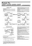
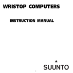
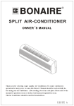
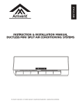
EN | FR | DE | ES | IT | NL | FI | SV
USER’S GUIDE
Suunto Oy 6/2001, 7/2005
COPYRIGHT
This publication and its contents are proprietary to Suunto Oy.
Suunto, Wristop Computer, Suunto Observer, Replacing Luck and their logos are registered or unregistered trademarks
of Suunto Oy. All rights reserved.
While we have taken great care to ensure that information contained in this documentation is both comprehensive and
accurate, no warranty of accuracy is expressed or implied. Its content is subject to change at any time without notice.
EN
USER'S GUIDE
CUSTOMER SERVICE CONTACTS
Suunto Oy
Suunto USA
Phone +358 9 875870
Fax +358 9 87587301
Phone 1 (800) 543-9124
Canada
European Call Center
Suunto Website
Phone 1 (800) 776-7770
Phone +358 2 284 11 60
www.suunto.com
1
TABLE OF CONTENTS
CHAPTER 1 INTRODUCTION .................................................................... 5
1.1 General Information .......................................................................................... 5
1.2 Care and Maintenance ...................................................................................... 5
1.2.1. Care of the Suunto Observer .................................................................. 5
1.3 Water Resistance ............................................................................................... 6
1.4 Battery Replacement ......................................................................................... 6
1.5 Adjusting the Bracelet (St and Tt models) ....................................................... 8
1.6 Main Functions (Modes) .................................................................................... 9
1.7 Backlight Features ............................................................................................. 9
1.8 Button Functions ................................................................................................ 9
1.9 LCD Display ...................................................................................................... 10
1.10 Measurements and Units ................................................................................. 11
1.10.1 To Set or Check Unit of Measurement Settings ............................... 11
1.11 Pressure Sensor Calibration ............................................................................ 12
CHAPTER 2 TIME MODE .......................................................................... 13
2.1 Setting up the Time and Calendar ................................................................ 13
2.2 Chronometer Sub Mode .................................................................................. 14
2.2.1 How to Use the Chronometer ................................................................. 14
2.2.2 To View the Chronometer Memory ....................................................... 15
2.3 Daily Alarm Sub Mode .................................................................................... 16
2.3.1 Setting the Daily Alarm(s) ...................................................................... 17
CHAPTER 3 ALTIMETER MODE ............................................................... 17
2
3.1 Altimeter-Barometer Use ................................................................................. 18
3.2 Setting the Altimeter ........................................................................................ 19
3.3 Logbook Sub Mode ......................................................................................... 21
3.3.1 Starting and Stopping a Logbook Recording ....................................... 21
3.3.2 To View in the Logbook Mode .............................................................. 21
3.4 Fast Cumulative Feature ................................................................................. 23
3.5 Logbook History Sub Mode ............................................................................. 23
3.5.1 Clearing the Logbook History ................................................................. 24
3.6 Effect of Air Temperature on Altitude Measurement ..................................... 25
CHAPTER 4 BAROMETER MODE ............................................................. 28
4.1 Setting the Sea Level Pressure ...................................................................... 29
4.2 4-Day Memory Sub Mode ............................................................................... 30
4.3 Barometric Trend Indicator ............................................................................. 31
CHAPTER 5 COMPASS MODE .................................................................. 31
5.1 Bearing Tracking Sub Mode ........................................................................... 32
5.2 Declination Adjustment Sub Mode ................................................................. 33
5.2.1 Setting the Local Declination ............................................................... 33
5.3 Calibrating the Compass ................................................................................. 34
CHAPTER 6 FREQUENTLY ASKED QUESTIONS .................................... 35
CHAPTER 7 ABBREVIATIONS ............................................................... 38
CHAPTER 8 COPYRIGHT AND TRADEMARK NOTICE ........................... 39
CHAPTER 9 CE COMPLIANCE ............................................................... 39
CHAPTER 10 LIMITS OF LIABILITY AND ISO 9001 COMPLIANCE ......... 40
CHAPTER 11 DISPOSAL OF THE DEVICE ................................................ 40
3
Figure 1.1
a)
f)
SELECT
MODE
b)
PRESSURE
SENSOR
ON / OFF
QUICK
- Altitude Alarm Indicator
- Daily Alarm Indicator
- Mode Indicator
- AM/PM Indicator (12h display)
- Low Battery Indicator
- Use Indicator
- Chronometer Indicator
4
d)
e)
c)
CHAPTER 1 INTRODUCTION
1.1 GENERAL INFORMATION
The Observer Wristop Computer is a reliable high precision electronic instrument,
intended for recreational use. The outdoor enthusiast who enjoys venturing in sports like
skiing, kayaking, mountain climbing, hiking and biking can rely on the Observer’s accuracy.
NOTE: The Observer should not be substituted for acquiring measurements that require
professional or industrial precision and should not be used to acquire measurements
when skydiving, hang gliding, paragliding, gyrocopter riding and flying small aircraft.
The Observer is available in three different material combinations:
Observer Sr with stainless steel housing and elastomer strap, Observer St with stainless
steel housing and stainless steel / elastomer bracelet and Observer Tt with Titanium
housing and Titanium / elastomer bracelets. All material versions have identical functions
and operation.
1.2 CARE AND MAINTENANCE
1.2.1 Care of the Suunto Observer
Only perform the procedures described in this manual. Never attempt to disassemble or
service your Suunto Observer. Protect your Suunto Observer from shocks, extreme heat
and prolonged exposure to direct sunlight. Avoid rubbing the Suunto Observer against
rough surfaces as this may scratch the face. If not in use, your Suunto Observer should be
stored in a clean, dry environment at room temperature.
The Suunto Observer can be wiped clean with a lightly moistened (warm water) cloth.
If there are stubborn stains or marks, you can apply mild soap to the area. Do not expose
the Suunto Observer to strong chemicals such as gasoline, cleaning solvents, acetone,
alcohol, insect repellents, adhesives and paint, as they will damage the unit’s seals,
case and finish. Make sure the area around the sensor is kept free of dirt and sand. Never
insert any objects into the sensor opening.
5
1.3 WATER RESISTANCE
Suunto Observer is tested with ISO (International Organization for standardization,
www.iso.ch) standard 2281. This means that the product is water-resistant. In addition to
the term ‘water resistant’, Suunto Observer is marked with an indication of a test
overpressure given as a depth in meters (100 m/330 feet). This indication, however,
does not correspond to a diving depth but refers to the pressure at which the water
overpressure test was conducted.
This means that you cannot dive to a depth of 100 m/330 ft. with your Suunto Observer.
Rain, showering, swimming and other normal exposure to water will not affect its operation
but the buttons shall not be pressed if exposed to water in any circumstances.
NOTE: Suunto Observer wristop computers must not be used for diving.
1.4 BATTERY REPLACEMENT
Suunto Observer operates on a 3-Volt lithium cell, type: CR 2032. The life expectancy
is approximately 12 months in the Time mode.
A low-battery warning indicator is activated on the display when approximately 5–15
percent of the battery capacity is still available. When this occurs, you should replace
the battery. However, extremely cold weather may activate the low battery warning
indicator even though the battery is still fully operational. If the battery warning indicator is activated in temperatures above 10°C (50°F), replace the battery.
NOTE: Heavy use of the backlight, altimeter and compass will significantly reduce
battery life.
You can replace the batteries yourself as long as you do it properly to avoid any leakage
of water into the battery compartment or computer. Always use original battery
replacement kits. (They include a new battery, battery lid and O-ring.) You can purchase
the battery kits from official Suunto retailers.
NOTE: When replacing the battery, also replace the battery lid and O-ring. Never use
the old ones.
6
NOTE: Change the battery at your own risk. Suunto recommends
you to have the batteries changed in official Suunto
services.
To replace the battery:
1. Insert a coin into the slot located on the battery
compartment cover on the backside of your Suunto
Observer.
2. Turn the coin counterclockwise until it is aligned
with the open position marker.
3. Remove the battery compartment cover and the
O-ring, and discard them. Ensure that all surfaces
are clean and dry.
4. Remove the old battery carefully.
5. Place the new battery into the battery compartment under the metal contact clips, with the positive side facing up.
6. With the O-ring in the correct position, replace the
battery compartment cover and turn it with the
coin clockwise until it is aligned with the closed
position marker. Do not press onto the battery compartment cover while turning it with a coin.
NOTE: Perform battery replacement with extreme care
to ensure that your Suunto Observer remains water
resistant. Careless battery replacement may void
warranty.
!
!
!
!
!
WARNING: This Suunto product contains a Lithium cell battery. To reduce risk of fire or
burns, do not disassemble, crush, puncture, short external contacts, charge or dispose
7
of in fire or water. Replace only with manufacturer
specified batteries. Recycle or dispose of used
batteries properly.
!
1.5 ADJUSTING THE BRACELET (ST
AND TT MODELS)
The metal / elastomer bracelets of the Observer
models St and Tt have to be adjusted for the
user. The steps are
1. Remove the buckle by releasing the spring
bars with pin, paper clip or other sharp object.
3. Shorten the bracelet by cutting along the
grooves on the inner surface of the bracelet.
You can do this for instance with scissors. If
you are unsure of the correct length, cut the
pieces one by one and test the length after
cutting each piece. Cut in turns from both sides
of the bracelet to keep the sides equally long.
Be careful in order not to shorten the bracelet
too much.
!
2. Remove both spring bars from the pin holes.
!
5. Attach the buckle to the bracelet by placing
the spring bars into the holes in the buckle. In
both sides of the buckle are holes for two different positions. This can be used for fine ad8
!
4. Replace the spring bars into the last pin holes
of both sides of the bracelet.
justing of the bracelet length. Make sure that the spring bars are positioned straight
in the buckle.
1.6 MAIN FUNCTIONS (MODES)
The Observer has four main modes: TIME, ALTIMETER, BAROMETER, and COMPASS.
In each of the features there are associated sub modes providing further enhancements
to its usefulness during your outdoor adventures. All key features and sub features will be
discussed in further detail following this chapter.
1.7 BACKLIGHT FEATURES
The Observer has an electroluminescent backlight. To activate the backlight, press and
hold the [MODE] button for 2 seconds. The backlight will remain on for approximately 10
seconds. If you press buttons to operate, the backlight remains on 10 seconds from the last
pressing.
1.8 BUTTON FUNCTIONS
The Observer is operated with four buttons as shown in Fig. 1.1: [MODE], [ON OFF],
[QUICK], and [SELECT].
The MODE Button
Located on the top right of the Observer performs the following functions:
• A short press allows you to move from one mode to the next (TIME, ALTI, BARO,
COMP).
• While in the sub mode level, a short press returns you to the main mode.
• During the setup process, a short press accepts all changes and exits the set function.
• A long press of 2 seconds activates the backlight feature.
The ON OFF Button
Located on the bottom right of the Observer performs the following functions:
• In the TIME Mode, the bottom field view can be scrolled displaying the calendar
9
•
•
•
•
date, seconds, or dual time.
During the setup process, a short press causes the selected value to increase.
For chronometer, a short press acts as a start/stop.
In ALTIMETER mode the logbook starts and stops with two short presses.
In the COMPASS mode, two short presses change between the normal compass and
bearing tracking feature.
The QUICK Button
Located on the bottom left of the Observer performs the following function:
• In the setup process, pressing the [QUICK] button causes the selected value to
decrease.
• In the TIME, ALTIMETER, or BAROMETRIC mode, a short press quickly displays the
cumulative information of the current logbook recording. Refer to Chapter 3, Fast
Cumulative Features for more information
• For chronometer, this button is used for lap times and zeroing.
• In COMPASS mode, a short press locks the bearing.
The SELECT Button
Located on the top left of the Observer performs the following functions:
• In a main mode level, a short press allows you to enter into the sub modes of the
particular function or return to the main mode.
• For entering the setup process, a long press of 2 seconds allows you to initiate
changes to the Observer’s functions.
• While in the setup process, a short press allows you to move between settable units
or values and determine preferences.
1.9 LCD DISPLAY
Designed to offer maximum clarity and simplicity the display is divided into several
areas as shown in Fig. 1.1.
10
a) The top field displays numbers or text depending on the mode or sub mode you are
viewing.
b) The middle field displays large numbers and/or the related unit of measure of a
function.
c) The bottom field displays either numbers and/or text.
d) The Mode Indictor Bar displays the main modes of the Observer. The half oblong
located just below the bar indicates the mode you are viewing. The halfshape
under the mode indicator indicates the Observer is being used as a
moon shape
barometer (weather station) or altimeter.
e) The outer circumference of the LCD graphically tracks the units of measure based on
the selected mode.
Barometric Trend Indicator provides a quick
f) On the top left, an arrow shaped
reference view of weather conditions.
1.10 MEASUREMENTS AND UNITS
The Observer supplies two units of measure: Metric or Imperial. Each unit can be
selected individually.
Metric Unit of Measure
m
m/min
ºC
hPa
Imperial Unit of Measure
ft
ft/min
ºF
inHg
1.10.1 To Set or Check Unit of Measurement Settings
If the mode indicator is not on TIME, press the [MODE] button until it is directly below
TIME.
1. Press the [MODE] and [SELECT] buttons simultaneously for 3 seconds to enter the
11
setup mode. The top field will display “SET” momentarily and then change to “UNI”.
NOTE: Setup mode will automatically exit if left idle for more than one minute.
2. Press the [SELECT] button for 2 seconds to view the first setting. You will see the first
unit flashing.
WARNING: If you perform a short press of the [SELECT] button while in the “UNI”
setting mode, you will switch to Pressure Sensor Calibration. Refer to the next section
for more details.
3. Press the [SELECT] button to move to the unit you want to change. You can change
the flashing unit. The units are in the following order: m/ft, m/min / ft/min, hPa/inHg,
ºC/ºF.
4. Press the [ON OFF] or [QUICK] button to toggle between the metric and imperial
settings.
5. To confirm the setting(s), press the [MODE] button.
6. To exit the setup process, press the [MODE] button again.
1.11 PRESSURE SENSOR CALIBRATION
WARNING: This is a FACTORY CALIBRATION SETTING. Do not enter this mode.
If you enter this mode in error, exit immesdiately by pressing the [MODE] or [SELECT]
button to return to the “UNI” setting mode. Normally there is no need to alter the
calibration.
If the Pressure Setting Calibration has been altered, you can return the factory setting.
Proceed as follows: In the calibration setting mode, scroll the barometric pressure value
up or down until text “dEF” appears. This is the factory setting. Then exit by pressing
[MODE].
12
CHAPTER 2 TIME MODE
There are three time sub modes: time, chronometer and alarms.
NOTE: These functions are accessible in the TIME mode, i.e. when the mode indictor is
below TIME.
In the watch time mode, the fields display the following data as shown in Fig. 2.1:
a) Day of the week;
b) Current time;
c) Date dd.mm in 24h display or mm.dd in 12h display, seconds or dual time according
to the last selection (changing data with the [ON OFF] button;
d) Am/pm indicator in 12 h display; and
e) Graphical display of seconds, once every two seconds a new segment lights up until
a full circle of segments (60 seconds) is lit.
2.1 SETTING THE TIME AND CALENDAR
1. In the main mode of the time function, press the [SELECT] button for 2 seconds to
begin the setup process. In the bottom field, seconds will begin to flash.
2. Press the [SELECT] button to move to the field you want to change. The order of
fields is seconds, minutes, hours, 12/24h, year, month, day, dual-time hours, dualtime minutes. You change the value in the field that is flashing.
3. Press the [ON OFF] button to scroll the value in the field up or the [QUICK] button to
scroll down. In the seconds field, the [QUICK] button resets the seconds to zero.
4. Press the [MODE] button to accept the changes made and exit the setup process.
NOTE: If the 12-hour clock is chosen either AM/PM will appear below the hour in the
middle field and the date shows the month first then the day.
Once you determine the year, month and day, the Observer will supply the day of the
week in the top field.
Setup mode will automatically be released if left idle for more than one minute.
13
The dual time will stay the same, even though the time in the main time mode is
adjusted. For example, if you set the dual time to show your home time, your home time
will always be displayed in the sub mode even if you travel to a different time zone and
adjust the time in the main time mode.
The dual time function is completely independent from the current time and does not
effect the alarms or the memory functions. These are dependent on the current local time
in the main time mode.
2.2 CHRONOMETER SUB MODE
In the TIME mode, press the [SELECT] button once to enter this sub mode.
The Observer chronometer feature:
• Can record 1-99 split and lap times; and
• Obtain a maximum range of one run (timing event) up to 24:00:00. Upon exceeding
this range the Observer will activate an audible sound indicating the timing process
has stopped.
In the chronometer mode, the fields display the following data as shown in Fig. 2.2:
a) Seconds and tenths of a second;
b) Hours and minutes;
c) Icon of a “stopwatch”; and
d) Current time.
2.2.1 How to Use the Chronometer
In the chronometer mode:
1. Press the [ON OFF] button to start the chronometer.
2. Press the [QUICK] button to store the lap time and split time into memory.
Lap and split times are displayed as follows:
In the top field the lap time is shown for the latest lap. The number of this lap is shown
in the bottom field “L #” (# = lap number). The lap time is displayed for five seconds
before the measured split time is displayed.
14
The split time is indicated by the abbreviation “SPL” (SPL = split) in the bottom field
displaying for five seconds before it returns to showing the run time.
NOTE: You can continuously press the [QUICK] button during this activity to record and
display new lap and split times up to 99 times.
3. Press the [ON OFF] button to stop the chronometer.
4. Press the [QUICK] button to reset the chronometer to zero once the chronometer is
stopped.
NOTE: The timing of another event cannot start until the stopwatch has been zeroed.
NOTE: Starting the timing of another event removes the data of the previous timing from
the memory.
NOTE: When the timing is going on, the chronometer remains active in the background
when you switch to other modes or sub modes. A stopwatch icon is displayed in the
bottom field to indicate that the chronometer function is active.
2.2.2 To View the Chronometer Memory
While in the chronometer mode, press the [SELECT] button for 2 seconds. This sub
mode features three main screens. You use the [ON OFF] button to advance through the
screens and the [QUICK] button to scroll back to the first screen.
The first screen (Fig. 2.3) displays:
a) The year of the timed event;
b) The time the event started to record;
c) The date of the timed event;
d) The stopwatch icon; and
e) The text “MEM” to indicate the memory view.
You press the [ON OFF] button to move to the next screen.
The second screen (Fig. 2.4) displays:
15
a) The total number of laps stored in the middle field; and
b) The text “MEM and “LAP” and the stopwatch icon in the bottom field.
You press the [ON OFF] button to move to the next screen. In this mode, you can view the
individual lap and split times, each displaying its information on separate screens. You
can view individual sets of lap and split times by using the [ON OFF] button to advance
through the screens and the [QUICK] button to scroll back to the first screen. The screens
are setup in chronological order beginning with lap 1.
These screens (Figures 2.5 and 2.6) display:
a) The seconds and tenths of seconds of the lap or split time in the top field;
b) The hours and minutes of the lap or split time in the middle field; and
c) The text “MEM” and the text “L #”(L # = Lap time number #) or “SPL” (SPL = split time)
in the bottom field. The stopwatch icon appears on the right side. The lap time will
be viewed first and then the corresponding split time will follow automatically.
NOTE: If a display is on for an extended period of time, the lap and split times will begin
to flash alternating at 4-second intervals. After10 minutes the wristop will exit this view
mode automatically.
Press the [ON OFF] button to continue viewing the reminder of lap and split times
recorded. When the last lap and split times have been viewed, the display will show the
finishing time of the event in middle field and the text “End” (indicating the end of
timing) in the bottom field.
Press the [MODE] button once to exit and return to the chronometer sub mode and a
second time to return to the main time mode.
2.3 DAILY ALARM SUB MODE
The Observer allows you to select and enter settings for up to three alarms.
In the TIME mode, press the [SELECT] button twice to enter this sub mode. (After
stopwatch)
16
In the Daily Alarm mode (Fig. 2.7):
a) “ON” or “OFF” (the activation status of an alarm) display in the top field;
b) The alarming time displays in the middle field; and
c) The alarm (1, 2, or 3) displays in the bottom field.
Press the [ON OFF] or the [QUICK] button to toggle between the alarms 1,2, or 3 and
view the settings for each alarm. If any of the alarms is activated, a bell icon displays
over the mode bar.
2.3.1 Setting the Daily Alarm(s)
1. Press the [ON OFF] or the [QUICK] button to select alarm 1,2, or 3.
2. Press the [SELECT] button for 2 seconds. In the top field, the “ON” or “OFF” will
begin to flash.
3. Press either the [ON OFF] or the [QUICK] button to toggle between “ON” and “OFF”.
4. At the setting desired, press the [SELECT] button to move to the next settings. They
follow in order hours, minutes. The field you can change is flashing.
5. Press the [ON OFF] button to scroll the value up or the [QUICK] button to scroll down.
6. At the alarm time desired, press the [MODE] button to accept the changes and exit
the setup process. An icon of a bell will appear at the bottom left side on the middle field
to signify an alarm has been activated.
The Alarm setup is complete. To activate up to three alarms, please repeat steps 1-6.
The alarm volume is not adjustable.
CHAPTER 3 ALTIMETER MODE
The Altimeter provides you with:
• An adjustable unit of measure either meter or feet: meter range -500 to 9000; ft
range -1,600 to 29500;
• A resolution of 1m or 3ft;
• A display up-date on the rate of vertical movement in intervals of 1 second for 3
17
minutes, then every 10 seconds or less;
• A logbook, recording 99 single logs including the total ascent, total descent, number
of runs, and the duration of the log.
• Altimeter-Barometer use feature
To view and use the Altimeter function:
Press the [MODE] button until the indicator is directly below ALTI.
In the ALTIMETER mode the fields display data as shown in Fig. 3.1:
a) The vertical ascent or descent rate in meters or feet per min;
b) The current altitude in increments of 1 meters or 3 feet (depending on the unit of
measure selected);
c) Altimeter mode and altimeter use indicator;
d) The current time; and
e) The outer circumference of the LCD graphically displays lit segments representing
the altitude over a full thousand meters or feet (one complete circle is equivalent to
1000 m or 1000 ft)
3.1 ALTIMETER-BAROMETER USE
The Observer can be used as either a weather station or altimeter. This operating
feature is chosen in the setup process while in the altimeter or the barometer mode. To
toggle between these icon positions, hold the [Select]-button in for 2 seconds and then,
press the [Quick] or [On Off]-button to lock in one of the functions.
The icon for this function is displayed under the corresponding mode indicator (ALTI or
shape. The position of the icon indicates whether the Observer
BARO) in a half-moon
is being used as a weather station (BARO) or altimeter (ALTI).
NOTE: This is different than moving between ALTI and BARO main modes.
THIS IS IMPORTANT.
The use indicator has to be in ALTI position, otherwise the altitude display
is fixed.
18
When Altimeter Use is selected:
• The unit will be used as an altimeter.
• All pressure changes are interpreted as altitude changes.
• The sea level pressure reading displayed in the barometer mode will not change,
even though the absolute pressure reading will change.
When Barometer Use is selected:
• The unit will be used as a weather station.
• The unit interprets all pressure changes as being due to a change in the weather.
• Measured changes will affect only the pressure reading displayed in the barometer
mode. Both sea level pressure and absolute pressure reading will change. These
changes won’t affect the altitude reading in the altimeter mode while barometer use
is activated.
The Observer leaves the factory set to be used as an altimeter.
3.2 SETTING THE ALTIMETER
In setting the Altimeter, there are two processes that can be performed:
• The Reference Altitude (known altitude at the current location); and
• The Altitude Alarm (signals you when a certain programmed altitude is reached).
IMPORTANT NOTE:
In order to set the altitude in the Altimeter mode, the altitude must be known. That
information can be found by utilizing a topographical map, identifying the current
location with the associated altitude marked. You can proceed and follow the
instructions, setting the altimeter, provided in the section below.
If the Altitude is not known, you can set the sea level pressure in the Barometric mode.
Refer to Chapter 4, Setting the Sea Level Pressure.
Setting the Sea Level Pressure will adjust the altimeter to the current altitude within
approximately ten meters or 30 ft.
19
For information regarding the effect of air temperature on altitude measurement refer to
the last section of Chapter 3.
Information on the current sea level pressure can be obtained through newspapers,
local news and radio weather reports, the local airport facility or through the Internet
under local weather.
To set the altimeter:
1. In the altimeter main mode (mode indicator below ALTI), Press the [SELECT] button
for 2 seconds. In the top field, the text “RE” (indicating reference altitude) displays. In
the middle field, the current altitude displays. In the bottom field the half-moon
shaped use indicator under the indicator bar will begin to flash (Altimeter-Barometer
use feature) and the text “USE” will appear.
2. Press either the [ON OFF] or [QUICK] button to toggle the icon to the position under
“ALTI” (for altimeter use) or “BARO” (for barometer use).
3. At the desired preference, press the [SELECT] button to move to the next setting. In
the middle field, the reference altitude value will begin to flash.
4. Press either the [ON OFF] button to scroll the value up or the [QUICK] button to scroll
down.
5. At the desired reference altitude, press the [SELECT] button to move to the next
setting (Altitude Alarm setting). In the top field, the “ON” or “OFF” will begin to flash.
6. Press either the [ON OFF] or the [QUICK] button to toggle between the “ON” and
“OFF” for the Altitude Alarm.
NOTE: An activated altitude alarm is indicated with an alarm symbol.
7. At the desired setting, press the [SELECT] button to move to the next setting. In the
middle field, the alarm altitude will begin to flash.
8. Press either the [ON OFF] button to scroll the value up or the [QUICK] button to scroll
down.
20
9. At the desired altitude, press the [SELECT] button to view the setup preferences for
confirmation or for additional changes, or press the [MODE] button to accept the
changes and exit.
NOTE: You can return to main ALTI display by pressing [MODE] during any of the steps
1-9.
Once you have set the reference altitude of the current location to the known altitude,
the Observer will also correct the sea level pressure, and therefore, it will not be necessary
for this function to be set.
NOTE: Setup mode will automatically be released if left idle for more than one minute.
3.3 LOGBOOK SUB MODE
3.3.1 Starting and Stopping a Logbook Recording
In the main altimeter mode, a logbook recording starts by performing two short presses
of the [ON OFF] button. An ongoing recording is indicated with flashing “LOG” text in the
bottom field. To stop a logbook recording, you must be in the altimeter mode and
perform two short presses of the [ON OFF] button again.
The memory capacity is 99 logs, each at maximum 20 hour duration. After recording
the 99th logbook, the Observer writes the next logbook over the logbook number 1 (the
oldest log) and then continues in numeric order.
The logbook is recording in 10-second intervals, which is quick enough for all activities.
It is not possible to view the individual values of the logbook.
NOTE: You can be in other modes while recording. To indicate logbook-recording
activity, the Observer will display the text “LOG” flashing in the bottom field.
3.3.2 To View in the Logbook Mode
In the Altimeter mode, press the [SELECT] button once to enter this sub mode. The
logbook mode features five screens. The first screen displays for 7 seconds. Thereafter,
21
the screens will increment (2-5) displaying at four-second intervals.
1. The first screen (Fig. 3.2):
• The top field displays the year;
• The middle field displays the text “LO” (LO = logbook) with the current logbook
number flashing; and
• The bottom field displays, the month and day of which the particular logbook was
recorded. To the left of the date, is the text “Log”.
To view previous logs captured, press the [QUICK] button to scroll down.
2. The second screen (Fig. 3.3) shows the ascent information for the particular logbook
that is being viewed.
• The top field displays the average ascent rate during the event.
• The middle field displays the total vertical ascent.
• The bottom field displays the text “ASC” along with the text “Log” to the left.
NOTES: The maximum asc/dsc that can be shown in one logbook is 39,999 m / ft. After
this number the counter starts again at zero.
3. The third screen (Fig. 3.4) shows the descent information for the particular logbook
that is being viewed.
• The top field, the average descent rate during the event.
• The middle field, the total vertical descent.
• The bottom field, the text “dSC” along with the text “Log” to the left.
4. The fourth screen (Fig. 3.5) shows the number of laps (runs) completed for the
particular logbook that is being viewed.
• The middle field, the total number of ascents or descents.
• The bottom field, the text “LAP” along with the text “Log” to the left.
NOTE: A lap is a vertical movement including both ascent and descent equaling 50
meters (150 ft) or above. The first lap can be also only descent.
5. The fifth screen (Fig. 3.6) shows the time duration of recording information in the
22
particular logbook that is being viewed.
• The middle field, the total time of the log.
• The bottom field, the text “dUr” (dUr = duration) along with the text “Log” to the left.
NOTE: Logbooks are self-erasing and cannot be cleared by you.
3.4 FAST CUMULATIVE FEATURE
This feature allows you to check the cumulative vertical ascent/descent in feet or meters,
as well as number of runs of the current logbook while recording.
You can access this information by performing a short press of the [QUICK] button in any
of the TIME, ALTIMETER, or BAROMETER main modes. When activated, three screens
will appear and automatically rotate in intervals of four seconds (as in the figures for
steps 2, 3, and 4 of the Logbook Mode).
• The first screen shows the rate of ascent and the accumulative vertical ascent since
the beginning of the current logbook.
• The second screen shows the rate of descent and the accumulative vertical descent
since the beginning of the current logbook.
• The third screen shows the number of laps (runs) accomplished during the current
logbook.
After the third display is shown, the Observer automatically returns to the main mode in
which you were viewing.
NOTE: During this process, pressing the [QUICK] button allows you to move on to the
next screen.
3.5 LOGBOOK HISTORY SUB MODE
The Logbook history shows a summation of all logs recorded.
In the Altimeter mode, press the [SELECT] button twice to enter this sub mode. There
are four screens displayed in the logbook history.
In the first screen (Fig. 3.7):
23
•
•
•
The top field displays the year when the logbook history was last cleared;
The middle field displays the text “HIS” (“HIS” = history); and
The bottom field displays the month and day when the logbook history was last
cleared.
Press [ON OFF] button to scroll through the remaining three screens. (Press the [QUICK]
button the scroll back to the first screen.)
In the second screen (Fig. 3.8):
• The top field displays the text “HI”;
• The middle field displays the highest altitude recorded since the last date cleared;
and
• The bottom field displays the date when it was reached with the date and year
alternating.
In the third screen (Fig. 3.9):
• The top field displays the text “ASC”; and
• The middle and bottom fields display up to an 8 digit accumulative vertical ascent
since the last reset. The middle field is activated when the value of the vertical
ascent is beyond the 3-digit value displayed in the bottom field.
In the fourth screen (Fig. 3.10):
• The top field displays the text “dSC”; and
• The middle and bottom fields display up to an 8 digit accumulative vertical descent
since the last reset. The middle field is activated when the value of the vertical
ascent is beyond the 3-digit value displayed in the bottom field.
Press either the [SELECT] or the [MODE] button to exit this activity.
3.5.1 Clearing the Logbook History
To clear the history of the logbook:
1. In any of the logbook history screens, press the [SELECT] button for 2 seconds. The
top field displays the text “CLR”, the middle field the text “HIS”, and the bottom field
the text “nO”. All three messages will begin to flash.
24
2. Press either the [ON OFF] or the [QUICK] button to toggle between “YES” and “nO”.
3. Press the [MODE] button to accept the preference “YES” and exit.
The logbook history is erased and a new starting date will be set to begin new cumulative
measurements.
NOTE: Setup mode will automatically exit if left idle for more than one minute.
We recommend that the logbook history be cleared prior to beginning logbook
recording(s).
3.6 EFFECT OF AIR TEMPERATURE ON ALTITUDE MEASUREMENT
The atmospheric pressure means the weight of air mass above the observer: at a higher
altitude there is less air than at a lower altitude. The principle of an altimeter is to
measure the different air pressure between different altitudes.
The outside temperature affects the air weight. Consequently the air pressure difference
between two altitudes is also dependant on temperature.
The altitude calculation of the Observer is based on the air pressure at certain normal
temperatures. Each altitude has a definitive normal temperature. The normal
temperatures at each altitude are presented in Table 1.
25
Table 1. Normal temperatures corresponding to different altitudes
Altitude (m)
Altitude (ft)
above sea level above sea level
0
0
200
656
400
1312
600
1969
800
2625
1000
3281
1200
3937
1400
4593
1600
5250
1800
5906
2000
6562
2400
7874
2800
9187
3000
9843
3400
11155
3800
12468
4000
13124
4500
14765
5000
16405
5500
18046
6000
19686
26
Temperature
15.0
13.7
12.4
11.1
9.8
8.5
7.2
5.9
4.6
3.3
2.0
-0.6
-3.2
-4.5
-7.1
-9.7
-11.0
-14.3
-17.5
-20.8
-24.0
(ºC)
Temperature
59.0
56.7
54.3
52.0
49.6
47.3
45.0
42.6
40.3
37.9
35.6
30.9
26.2
23.9
19.2
14.5
12.2
6.4
0.5
-5.4
-11.2
(ºF)
The altitude measurement error caused by an abnormal temperature gradient can be
approximated as follows. If the sum of the temperature offsets from the normal
temperatures determined at two different altitudes is 1 ºC, the altitude
difference calculated by the Observer is 0.2% off the real altitude
difference (When using imperial units the offset factor is 0.11% / 1 ºF). This is because
the real temperatures are not always the same as the normal temperatures. A higher
than normal temperature causes the calculated altitude difference to be smaller than
the real altitude difference (your mountain ascent was actually higher). Consequently, a
lower than normal temperature causes the calculated altitude difference to be larger
than the real altitude difference (you did not ascend quite as high as displayed).
Table 2 shows an example in which the temperature offsets are positive. In this example,
the reference altitude is set at 1000 m. At 3000 m the altitude difference is 2000 m and
Observer shows 80 m too little (20 ºC * 2000 m * 0.002/ºC = 80 m). Your actual altitude
is thus 3080 m.
All Suunto products with altimeter are temperature calibrated. This means that at
constant pressure, the reading of the pressure sensor is always the same independent of
the unit’s own temperature. However, the air temperature can still effect the altitude
readings as described above.
Table 2. Example using meters and Celsius
Lower point
Set reference altitude (real altitude)
Displayed altitude
Real outside temperature
Normal (table) temperature
Temperature offset (= real - normal)
Sum of temperature offsets
Higher point
1000 m
+17.5 ºC
+8.5 ºC
+9 ºC
+9 ºC + +11 ºC = 20 ºC
3000 m
+6.5 ºC
-4.5 ºC
+11 ºC
27
Table 3 shows an example in which the temperature offsets are negative. This time
imperial units are used. The reference altitude is set at 3280 feet. At 9840 feet the
altitude difference is 6560 feet and Observer shows 100 feet too much (-14 ºF * 6560 ft
* 0.0011/ºF = -100 ft). Your actual altitude is thus 9740 ft.
Table 3. Example using feet and Fahrenheit.
Lower point
Set reference altitude (real altitude)
3280 ft
Displayed altitude
Real outside temperature
+36.3 ºF
Normal (table) temperature
+47.3 ºF
Temperature difference (= real - normal)-9 ºF
Sum of temperature offsets
-9 ºF + -5 ºF = -14 ºF
Higher point
9840 ft
+18.9 ºF
+23.9 ºF
-5 ºF
CHAPTER 4 BAROMETER MODE
The Barometer provides you with:
• An adjustable unit of measure hPa or inHg; hPa range 300 to 1100 hPa, inHg range
8.90 to 32.40;
• A resolution of 1 hPa or 0.05 inHg;
• A one hour interval measuring to estimate barometric trend;
• An automatic 4-day memory of atmospheric pressure;
• Temperature compensation (temperature does not effect the pressure within the
specified temperature range);
• A temperature range -20º to 60ºC or -5º to 140ºF;
• A temperature resolution of 1º C or F; and
• An Altimeter-Barometer use feature. Refer to Chapter 3, Altimeter-Barometer Use for
more information.
28
NOTE: To acquire true temperature reading, take the Observer away from wrist and
allow it to adjust to the ambient temperature for 15 minutes.
To view and use the Barometric function:
Press the [MODE] button until the mode indicator is directly below BARO.
In the Barometric mode the fields display information as shown in Fig. 4.1:
a) The top field displays the current temperature and barometric trend indicator;
b) The middle field displays sea level pressure;
c) The bottom field displays either the current time or the current absolute atmospheric
pressure. (Press the [ON OFF] button to toggle between the two values); and
d) The outer circumference of the LCD graphically displays lit segments of the atmospheric pressure over 100 hPa or 1 inHg where one complete circle is equivalent to
100 hPa/1 inHg, depending on the unit of measure chosen.
NOTE: The absolute pressure is the actual pressure in any location at any given time.
The sea level pressure is the corresponding pressure at sea level.
NOTE: The absolute pressure is depending on current altitude and weather.
4.1 SETTING THE SEA LEVEL PRESSURE
Setting the sea level pressure can be used in setting the altitude measurement if the
altitude is not known.
To set the sea level pressure:
1. In the barometric main mode, press the [SELECT] button for 2 seconds. The top field
displays the text “SEA”; the middle field displays the current sea level pressure, and
under the indicator bar
in the bottom field the half-moon shaped use indicator
will begin to flash (Altimeter-Barometer use feature) and the text “USE” will appear.
2. Press either the [ON OFF] or [QUICK] button to toggle the icon to the position under
“ALTI” (for altimeter use) or “BARO” (for barometer use).
3. At the desired preference, press the [SELECT] button. In the middle field, the sea
29
level pressure value will begin to flash.
4. Press the [ON OFF] button to scroll the value up or the [QUICK] button to scroll down.
5. When the current sea level pressure is displayed, press the [MODE] button to accept
the changes and exit.
Once you complete this process, the altitude measurement on the Observer should be
correct within a range of approximately ten meters or some tens of feet.
NOTE: Information on the current sea level pressure can be obtained through
newspapers, local news and radio weather reports, the local airport facility or through
the Internet under local weather.
NOTE: Setup mode will automatically be released if left idle for more than one minute.
4.2 4-DAY MEMORY SUB MODE
In the Barometric mode, PRESS the [SELECT] button once to enter this sub mode. This
feature allows you to follow changes in pressure that will assist you in forecasting
changes in weather condition (i.e. storms).
In the 4-day memory mode the display fields are as shown in Fig. 4.2:
a) The top field displays the day of the week;
b) The middle field displays the sea level pressure;
c) The bottom field displays the time corresponding to the pressure in the middle field
and the text “MEM”; and
d) The outer circumference of the LCD graphically displays the atmospheric pressure
where one full circle equals 100 hPa or 1 inHg.
To view the information compiled in the 4-day memory:
Press the [QUICK] button to scroll through the history of recordings beginning with
increments of one hour for the first six hours, after that increments are 6 hours.
Press the [ON OFF] button to scroll back up to the most recent recording.
30
4.3 BAROMETRIC TREND INDICATOR
The Barometric Trend Indicator is located in the top left corner of the LCD display. When
the barometer use feature is on, this indicator is displayed in all main modes to provide
you with an indication of upcoming weather conditions. If altimeter use is activated, the
trend indicator is not shown.
The Barometric trend is comprised of two lines forming an arrow. Each line represents a
3-hour period. The right line represents the last 3 hours. The left line represents 3 hours
prior to the last 3 hours. The line can indicate 9 different patterns in the barometric
trend. Examples:
Situation 6-3 hours ago
Situation last 3 hours
Dropped heavy (>2 hPa/3hours)
Dropping heavy (>2 hPa/3hours)
Remained stable
Rising heavy (>2 hPa/3hours)
Risen heavy (>2 hPa/3hours)
Dropping heavy (>2 hPa/3hours)
CHAPTER 5 COMPASS MODE
The Compass provides you with:
• A resolution of 1º for the bearing, and ±5º for North-South direction;
• A bearing tracking mode that’s used to indicate desired direction and actual bearing.
• A declination correction feature; and
IMPORTANT NOTE: To reach as accurate compass readings as possible, keep the
Observer in a level position.
In the compass mode, the fields display the following data as shown in Fig. 5.1:
a) The top field displays a cardinal or half cardinal point abbreviation;
31
b) The middle field displays bearing in degrees;
c) The bottom field displays current time; and
d) The outer circumference of the LCD graphically displays lit segments representing
a North-South arrow; (one-lit segment indicates North, three-lit segments indicate South)
To view and use the Compass function:
Press the [MODE] button until the mode indicator is directly below COMP.
The compass display is active for 45 seconds at a time. After this, the compass enters
“sleep” mode for power saving and an “- - -°” indicator appears in the middle field. To
reactivate the compass, press the [QUICK] button.
NOTE: Compass readings should be performed away from objects possessing sources
of magnetism. Avoid large metal objects, power lines, loudspeakers, electric motors etc.
This type of disturbances cause relatively often need to calibrate the compass.
Always take bearings in the open air, not inside buildings, tents, caves, or other
shelters.
5.1 BEARING TRACKING SUB MODE
In the compass mode you can select to change from the cardinal point mode to the
bearing track mode and utilize the bearing lock feature for tracking purposes.
In the bearing tracking mode, the fields display data as shown in Fig. 5.2:
a) Locked bearing in degrees
b) Actual bearing in degrees
c) Current time
d) The outer circumference of the LCD graphically displays the difference of the locked
and actual bearing. The end of the lit segments indicates the direction of the
bearing to be tracked.
To activate the bearing tracking mode press the [ON OFF] button twice. If active, press
the [ON OFF] button twice to deactivate.
32
To set the bearing lock
1. Press the [SELECT] button for 2 seconds to start the setup process. Located in the
middle field, the actual bearing in degrees will begin to flash.
2. Turn the Observer to the desired direction. Lock the bearing displayed by pressing
the [QUICK] button.
3. To adjust the locked bearing, press the [SELECT] button once, so that the locked
bearing in the top field starts to flash. Then adjust the value with the [ON OFF] and
[QUICK] buttons.
4. At the desired bearing to track, press the [MODE] button to accept the changes and
exit the setup program.
NOTE: The above steps can also be performed in the main compass mode.
Setup mode will automatically be released if left idle for more than one minute.
5.2 DECLINATION ADJUSTMENT SUB MODE
The Observer allows you to compensate for the difference between true north and
magnetic north by adjusting the compass declination.
In the Compass mode, press the [SELECT] button once to enter this sub mode. The
display is shown in Fig. 5.3:
• The top field displays the current declination direction where OFF = no declination;
W = West; E = East;
• The middle field displays declination in degrees; and
• The bottom field displays the text “dEC”.
5.2.1 Setting the Local Declination
1. Press the [SELECT] button for 2 seconds. In the top field, the text “OFF” will begin to
flash.
2. Press the [ON OFF] or the [QUICK] button to select the declination direction in the
top field.
33
3. Press the [SELECT] button to move to the next setting. In the middle field, the
degrees will begin to flash.
4. Press the [ON OFF] button to scroll the degrees up or the [QUICK] button to scroll
down.
5. At the degrees desired, press the [MODE] button to accept the changes and exit.
Local Declination is now set.
NOTE: You can find the local declination in the maps of your area.
Setup mode will automatically exit if left idle for more than one minute.
5.3 CALIBRATING THE COMPASS
A compass calibration should be done whenever the Observer is exposed to a strong
magnetic source, extreme cold weather, the battery is replaced, or you suspect that other
environmental conditions have affected the compass readings. If you notice that the
compass is not showing the direction correctly, you should do the calibration.
NOTE: Calibrate the compass before you use it for the first time, and before you leave
for an extended outdoor activity.
To begin the calibration:
1. Press the [SELECT] button twice when in the main compass mode. The top field
displays the text “CMP”, and the bottom field displays the text “CAL” (Fig. 5.4).
2. Press the [SELECT] button for 2 seconds. In the middle field, the text “PUSH” will
begin to flash, alternating with the sign “-” (Fig. 5.5). This indicates the button
[QUICK / -].
3. Press the [QUICK] button to start calibration. The middle field displays 360º and the
LCD ring on the outer circumference light (Fig. 5.6).
4. Hold the Observer level and slowly rotate the device in a full clockwise or counterclockwise circle. As you turn, the lit LCD segments will turn off.
34
NOTE: For successful calibration, it is important to hold the Observer level during the
calibration process. This is simple to accomplish. For example, place the Observer on
an over-turned drinking glass on a table.
5. Within a minute of completing a full circle, the Observer will inform you whether the
calibration was successful by displaying the text “dOnE” in the middle field (Fig. 5.7),
or if the calibration needs to be repeated by displaying “PUSH” and “-” (Fig. 5.5).
NOTE: you may need to perform the rotating of the compass more than twice around for
the calibration to be completed.
NOTE: If the text “FAIL” appears in the middle field, the battery should be removed and
put back in before trying to proceed with the calibration process. The removal of the
battery will “reset” the unit.
6. Once the calibration is successful, press the [MODE] button to accept calibration.
Press the [MODE] button a second time to return to main compass mode.
The compass calibration is complete.
CHAPTER 6 FREQUENTLY ASKED QUESTIONS
How long does the battery last?
The normal lifetime expectancy is 12 months. Battery life depends mainly on how much
the backlight, the compass and the logbook are used. The low-battery warning symbol
appears on the display when 5 to 15 percent of battery capacity remains. Which gives
you plenty of time to safely change the battery.
Why is the altitude reading not changing even though I’m moving
in a vertical direction?
You are using the Observer as a barometer and the altitude is fixed. To change to the
altimeter use, enter settings in the BARO or ALTI mode. The first thing that you can set
35
is the choice between Altimeter/Barometer Use. Refer to Chapter 3, Altimeter-Barometer
Use.
Why does the vertical ascent/descent measurement show different
readings even though I am inside and staying in the same room?
Indoors, even small, unnoticeable air currents cause changes in air pressure. For example,
if you have a window open at the other end of your house, the air current may affect a
room at the other end of the building so little that you don’t notice it, but the sensors of
the Observer do. Because the Observer measures ascent and descent based on changes
in air pressure, it interprets these changes as vertical movement.
What happens after the 99th logbook?
After recording the 99th logbook, the Observer writes the next logbook over the logbook
number 1 (the oldest log) and then continues in numeric order.
What is the maximum capacity of total vertical ascent or descent
feet/meters in the logbook history?
The maximum figure that can be shown on the display is 39,999.999 representing feet
or meters depending on the unit of measurement set. This should be enough for most
users: 39,999.999 meters is roughly three-quarters around the globe.
What is the duration readout?
The duration readout tells you how many hours and/or minutes the event recorded into
the logbook lasted. For example, if you’re hiking from 1 p.m. to 6 p.m. and the logbook
is on during this time, the readout would show a duration of 5:00 hours.
Does the Observer show future trends in weather conditions?
No, the Observer continually accumulates data on barometric pressure and stores the
data of last 4 days. The barometric trends of the last 6 hour window is displayed
graphically with an arrow in the top field. The Observer does not make forecasts of the
36
future weather, it stores data that supports you doing this. Remember that estimating the
coming weather should be based on different signs of nature in addition to the barometric
trend.
What does “absolute pressure” and “sea level pressure” mean?
Absolute pressure is the actual pressure in any location at any given time. Sea level
pressure equals the corresponding pressure at sea level for a certain altitude that you are
at. For example, if you are at an altitude of 1,000 m/3,300 ft the absolute pressure
normally is around 900 hPa/26.60 inHg. The relative pressure at sea level would then
be around 1,013 hPa/29.90 inHg.
What is temperature compensation?
When the unit is temperature compensated, the temperature of the unit itself does not
affect the altitude measurement of the unit. The unit can be worn on your wrist or placed
on a table - it will in either case give you the proper altitude reading providing the
weather conditions have not changed. All Suunto Observers are temperature
compensated within the range -5 to 140 ° F / - 20 to +60 ° C. Refer to Chapter 3, Effect
of Air Temperature on Altitude Measurement.
Why is the compass not working correctly?
It has been exposed to external electromagnetic disturbance and has to be calibrated.
Refer to Chapter 5, Calibrating the Compass.
Where do I find the correct declination for my area so I can set my
Observer?
Local declination, either E or W, is usually marked on maps with either one-degree or
half-degree accuracy.
When should I operate the Observer in Altimeter Use and when in
Barometer Use?
Altimeter Use (half-moon
indicator below ALTI in the mode bar) is your choice when
37
you want to measure the altitude and there is vertical movement included in your
activity. Barometer Use is suitable for weather measurements.
A natural way to alternate between Altimeter/Barometer Use during a hike is to use the
Observer as altimeter when moving and as barometer when camping (no vertical
movement expected). This way you will have more accurate information on both altitude
and weather. Refer to Chapter 3, Altimeter-Barometer Use.
NOTE: The modes TIME, ALTI, BARO, and COMP are different from the main operational
USE between Altimeter and Barometer.
What do the LCD segments on the circumference mean?
In the Altimeter mode, one full circle equals 1,000 meters or 1,000 feet; therefore the
segments on the circumference graphically show you the altitude over a full thousand.
In the Barometer mode, one full circle equals 100 hPa or 1 inHg, and the segments
indicate the pressure over a full hundred hPa or over a full inHg.
In the main Compass mode, the segments indicate the North and South (one-lit segment
indicates North, three-lit segment indicate South). If you have set the compass to track
a certain bearing, the segments on the circumference indicate the difference between
the direction in which you want to go and your actual bearing.
CHAPTER 7 ABBREVIATIONS
dEF
SNR
RE
ASC
dSC
CLR
38
default factory setting of pressure sensor, corresponds to standard (1013 mbar or
29,90 inHg) airpressure at sea level
sensor (used in pressure sensor calibration)
reference altitude
ascent
descent
clear
bEG
dUR
SPL
MEM
HIS
CMP
CAL
begin
duration
split time
memory view
history
compass
calibration
CHAPTER 8 COPYRIGHT AND TRADEMARK NOTICE
This publication and its contents are proprietary to Suunto Oy and are intended solely
for the use of its clients to obtain knowledge and key information regarding the operation
of Suunto Observer Wristop Computer product.
Its contents shall not be used or distributed for any other purpose and/or otherwise
communicated, disclosed or reproduced without the prior written consent of Suunto Oy.
Suunto, Wristop Computers and their logos are all registered or unregistered trademarks
of Suunto Oy. All rights are reserved.
While we have taken great care to ensure that information contained in this
documentation is both comprehensive and accurate, no warranty of accuracy is expressed
or implied.
CHAPTER 9 CE COMPLIANCE
All Suunto Wristop Computers conform to the required European Union EMC directives
89/336/TEC.
39
CHAPTER 10 LIMITS OF LIABILITY AND ISO 9001
COMPLIANCE
If this product should fail due to defects in materials or workmanship, Suunto Oy will, at
its sole option, repair or replace it with new or rebuilt parts, free of charge, for two (2)
years from the date of its purchase. This warranty is extended only to the original
purchaser and only covers failures due to defects in materials and workmanship that
occur during normal use while in the period of the warranty.
It does not cover damage or failures resulting in accident, misuse, neglect, mishandling,
alteration or modifications of the product, or any failure caused by operation of the
product outside the scope of its published specifications, or any causes not covered by
this warranty.
There are no express warranties except as listed above.
The client can exercise the right to repair under the warranty by contacting our Customer
Service department to obtain a repair authorization.
Suunto Oy, Suunto Europe and Suunto USA/Canada shall in no event be liable for any
incidental or consequential damages arising from the use of or inability to use the
product. Suunto Oy does not assume any responsibility for losses or claims by third
parties that may arise through the use of this device.
Suunto’s Quality Assurance System is certified by Det Norske Veritas to be ISO 9001
compliant in all SUUNTO Oy’s operations (Quality Certificate No. 96-HEL-AQ-220).
CHAPTER 11 DISPOSAL OF THE DEVICE
Please dispose of the device in an appropriate way, treating it as
electronic waste. Do not throw it in the garbage. If you wish, you may
return the device to your nearest Suunto representative.
40