1
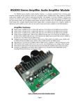
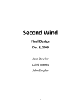
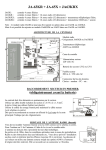
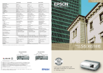
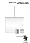
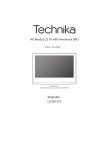
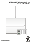
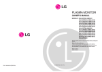
IRS2092S Audio Amplifier Kit IRS2092S Audio Amplifier kit The IRS2092S Audio Amplifier kit module is a Class D Audio Amplifier Kit based on IRS2092S class D amplifier modulator and driver made by International Rectifier®. The design of this board is in accordance with the manufacturer datasheet and recommendations, as well as the reference designs. Furthermore, some improvements has been made to make the board more compact and suitable to use both in new designs, in which the user will adopt the preferred housing, input stages and power supply, and can be used also as a drop-in replacement for existing audio amplifiers, which already have housing, transformer, and input stage. Amplifier Features: Output Power: 200W at 4Ω, or 120W at 8Ω, with less than 0.1% THD+N, at +/- 45V Supply Voltage. Output Power: 350W at 4Ω, or 180W at 8Ω, with less than 0.1% THD+N, at +/- 60V Supply Voltage. Output Power: 500W at 4Ω, or 270W at 8Ω, with less than 0.1% THD+N, at +/- 72V Supply Voltage. Audiophile sound Quality: 0.02% THD+N at 100W at 4Ω or 50W at 8Ω. High efficiency: Up to 96.4% at 270W at 8Ω or up to 94% at 500W at 4Ω. Output over-current and short-circuit protected, power supply over-voltage and under-voltage protection. Mute control pin for easily controlling the amplifier status within the system. Dedicated output MOS-FET choices for each power version for maximum performance and efficiency. Compact size, 100x70x35mm, low weight, just 120 grams. Optimized double layer 1.6mm thick PCB with thick copper traces, for lowest stray inductances. Only THD components used, except IRS2092S IC which uses SMD case and is pre-soldered. Figure 1: IRS2092S Audio Amplifier Kit Page 1 IRS2092S Audio Amplifier Kit Before you begin: IRS2092S Kit must only be assembled and used by skilled peoples with proper tools, equipment and at least basic knowledge in electronic and electrical field. This will prevent any possible causes of malfunction and will offer the DIY product satisfaction immediately. The following tools are the absolute minimum necessary: Two screwdrivers: 4mm slotted and 5mm cross-slot or Pozidriv, Wire cutters, pliers, needle nose pliers, tweezers. Electrical tool: 30-40W adjustable temperature (250-320*C) soldering iron. Universal digital Multimeter, highly recommended oscilloscope with at least 20MHz bandwidth and suitable probes with 1:1 and 1:10 attenuation capable to measure signals with up to 200Vpp. Lab Power supply with adjustable output voltage in range of 0 to +50V and up to 5A current capability with low current limit of 100mA for 200W Kit version or 0 to +-80V and up to 10A current capability with low current limit of 100mA for 350W and 500W kit version. Eventually a built-up power transformer with suitable output voltage and two 100R 10-100W power resistors can be used for tests if Lab Power supply isn’t available. In addition, wires for interconnections (only the signal wires with connector are provided ~20cm long, the power wires must be connected to on-board screw type terminal block) magnifier glasses, several small dishes to place the parts before assembly to avoid losing them, non-acid contact cleaner or better paint thinner to wash the board after assembly before power on first time. Safety comes first: Before beginning, ensure a safe and spacious enough working table, with good lighting and proper ventilation for fumes resulting from soldering process. Prepare the working space, a large table at least two square foot in size. Yes, we know the space is always a problem but we don’t recommend using the kitchen table as the solder droplets resulting from soldering process might be accidentally eaten at a later time. Wash your hands thoroughly and wash your working clothes separately than the rest of clothes. Do not allow children to play with modules, parts and never let them touch the solder wire or solder droplets. We all know that leaded solder is not tasty and is toxic, leading to possible lead poisoning if used very often but very few DIY’ers can solder properly using lead-free or RoHS solder which is much harder to use, require higher melting temperatures and the solder joints are prone to cracking more easily. Not to mention that the higher soldering temperature can damage the sensitive semiconductors and capacitors. For these reasons, the solder alloy is not provided, leaving the user choice what kind of solder to use for any particular project. From our experience the best solder for prototypes, kits and hand assembled modules is the 63/37 alloy which contains 63% tin and 37% lead forming eutectic alloy and have a rosin core. The 60/40 alloy can also be used but is not as easy to use as the 63/37 one. We do not recommend using lead-free solder or some “audiophile grade solder” simply because there isn’t audiophile solder. During the fist phase of the assembly, do not use any electricity powered tools except soldering iron. Check the power cable, body and tip integrity and use it only if doesn’t show signs of excessive wear or exposed conductors. Do not use the power supply yet till the amplifier is completed, verified and ready to be tested. Wear an earthed ESD wrist strap while assembly the board to prevent damaging sensitive components. The wrist strap must be a good quality one to prevent any possible accidents. Do not wear the wrist strap after assembly is done and the board is tested!!! After complete assembly, make sure you double check that all the components are properly soldered in their position and there are no swapped components values or wrong oriented. Use current limited power supply during first power on to prevent damage if something was installed wrong. The IRS2092S Kit only requires ~4080mA per rail for idle operation, two 100R at 10-100W can be used as current limiting resistors in series with each supply rail if a Lab power supply isn’t available. We recommend installing all the components except the few 2/3W power resistors as close as possible on the PCB Board, leaving no space between component and board. Resistors and non-polarized capacitors can be mounted in any direction while diodes, transistors and electrolytic capacitors can only be installed in one direction. If they are connected wrong, damage might occur or at least the amplifier kit will not work properly. Since the kit comes unassembled and the user have the responsibility to assembly and test properly, we do not offer any warranty as we offer for complete assembled and tested boards and products. The design was fully tested and optimized before we run batch manufacturing of PCB’s but there are so many things which can go wrong while assembly that is unreasonable to blame us for any possible failure. This kit is supplied with selected, high-quality original components only, so the quality of the components provided cannot be blamed in case of malfunction. Keep in mind all this aspects when consider purchasing the kit. Page 2 IRS2092S Audio Amplifier Kit Amplifier Description: IRS2092S Kit is a Single channel Class D Audio Amplifier using IRS2092S. Modulator/driver IC. Three output power versions are available: 200W/4R, 350W/4R and 500W/4R. The 200W and 350W power versions are using on-board heatsinks for power dissipation, while the 500W version can use either the standard on-board heatsinks if a cooling fan is used to provide airflow or a heaspreader to spread the heat to an external, larger heatsink. When purchasing the kit the standard heatsinks are provided, heatspreader must be sourced or manufactured by the user because its size depends on the available space in the enclosure where the IRS2092S amplifier kit will be installed. Only one differential voltage is required for each board version: +-45V (+-42 to +-46V range) for 200W version, +-60V (+-57 to +-64V range) for 350W version and +-72V (+-68V to +-77V range) for 500W version. If the power supply delivers lower voltage, out of range the amplifier might not start due to under-voltage protection, as well as if the voltage is higher out of range will not start due to over-voltage protection. Unless the voltage is significantly higher than maximum value (+25-30% or more) and is applied for short term damage will not occur. Any power supply capable to deliver from +-42V to +-46V and at least 3A per rail can be used for 200W IRS2092S Kit version, +-57V to +-64V and 4A or more per rail for 350W IRS2092S Kit version and +-68 to +-77V at 5A for 500W IRS2092S Kit version. Both linear power supply and SMPS can be used. The best performances can be achieved with SMPS due to the fact that the voltage drop is much smaller for a SMPS even unregulated type than a classic linear power supply where the output voltage tends to drop more. Excellent performances can be achieved using a regulated power supply. In addition, above a certain power level, usually 300-500W the SMPS becomes more economical than similar power rating Linear Power Supply while all the rest of advantages such as higher efficiency, lower size and weight, overload and S/C protection come as a bonus. One of the main advantages of a SMPS is that the most of the energy is stored in primary side high voltage capacitors which have a much better capacitance per volume ratio than lower voltage capacitors. For a linear power supply to achieve comparable performances with same power rating SMPS, required capacitance of the capacitors from each rail is much higher. If SMPS will be used, recommended SMPS for IRS2092 kit modules are: for 200W version one SMPS240QR +-45V for one IRS2092S kit and SMPS500(Q)R +-45V for 2 IRS2092S kits for 350W version one SMPS400QR +-60V for one IRS2092S kit and SMPS800RE +-60V for 2 IRS2092S kits for 500W version one SMPS500R +-72V for one IRS2092S kit and SMPS1200R +-72V for 2 IRS2092S kits If Linear Power supply will be used, below are the recommended values for the Power supply Mains power transformer and electrolytic capacitors for best performance application. A properly sized rectifier bridge must be used, rated for at least 25A at 200V for 200W and 350W IRS2092S kits and 35A at 400V or more for up to 4 IRS2092S kits and the mains transformer must have the power rating at least 0.8 x total amplifier power rating, the higher the better. The mains transformer must have two identical windings with output voltages of: 2x32 to 33V AC at 4A 250VA for single 200W IRS2092S kit, and 7A 450VA for two 200W IRS2092S kits 2x43 to 45V AC at 5A 450VA for single 350W IRS2092S kit, and 8A 750VA for two 350W IRS2092S kits 2x52 to 54V AC at 6A 650VA for single 500W IRS2092S kit and 11A 1200VA for two 500W IRS2092S kits The capacitance of the filter capacitors used on each rail of the power supply must be chosen as follows: For 200W version, the required minimum capacitance must be at least: 4700uF at 50-63V for +-45V (+-42V to +-46V) linear supply version supplying one 200W IRS2092S kit 10,000uF at 50-63V for +-45V (+-42V to +-46V) linear supply version supplying two 200W IRS2092S kits. 18,000uF at 50-63V for +-45V (+-42V to +-46V) linear supply version supplying four 200W IRS2092S kits. For 350W version, the required minimum capacitance must be at least: 4700uF at 70-80V for +-60V (+-57V to +-64V) linear supply version supplying one 350W IRS2092S kit 10,000uF at 70-80V for +-60V (+-57V to +-64V) linear supply version supplying two 350W IRS2092S kits. 18,000uF at 70-80V for +-60V (+-57V to +-64V) linear supply version supplying four 350W IRS2092S kits. For 500W version, the required minimum capacitance must be at least: 3900uF at 80-100V for +-72V (+-68V to +-77V) linear supply version supplying one 500W IRS2092S kit 8200uF at 80-100V for +-72V (+-68V to +-77V) linear supply version supplying two 500W IRS2092S kits 15000uF at 80-100V for +-72V (+-68V to +-77V) linear supply version supplying four 500W IRS2092S kits Page 3 IRS2092S Audio Amplifier Kit If the total system price is more important than performance, the absolute minimal configuration will use a simple mains transformer with suitable rated power and output voltages and one high current rectifier bridge only. The IRS2092S kit on-board capacitors will provide enough energy storage for most applications except subwoofer duty amplifiers which require extra capacitance to avoid premature shut-down or possible damage due to repeated bus-pumping which occur when very low frequency and high power signals are amplified. Eventually the on-board electrolytic capacitors supplied with the board can be replaced with larger ones which can fit on the board and offer enough capacitance to reduce bus pumping when no other power supply board is used, just mains transformer and rectifier bridge in low system cost implementations. Although music signal has a high crest factor, and the IRS2092S amplifier kit modules have very high efficiency, and the power rating of the transformer can be lower than the total power of the amplifiers, it must be at least half the total power of the amplifier modules supplied to prevent excessive voltage drop. Like everywhere there is a compromise between cost and performance. Following mains transformers voltage and current values are suitable: 250VA transformer for two 200W amplifier modules version with 2x32-33V AC 4A, 450VA transformer for two 350W amplifier modules version, with 2x43-45V AC, 5A and 625VA transformer for two 500W amplifier modules version with 2x52-54V AC, 6A. The audio input signal is provided to the IRS2092S kit on the signal connector Pin1. The Mute control which allows muting the amplifier when is pulled to GND with an external switch is available on signal connector Pin3. In the middle, Pin2 is the common GND connection. For maximum flexibility, the signal is fed into IRS2092S IC directly through an RC network without using any preamplifier or buffer, allowing the user to freely choose the best suitable front end for each application. The input impedance of the IRS2092S kit amplifier is 3.63Kr for 200W and 350W versions and 3.99Kr for 500W version. The resistors values from the feedback loop were chosen to offer same input sensitivity for all IRS2092S kit versions while achieving the rated power. The input sensitivity is 1.5V and overall gain is 18.9 for 200W version, 25.2 for 350W version and 30.2 for 500W version. The exact values are: 200W version: Input sensitivity for 200W: 1.49V gain: 18.9 350W version: Input sensitivity for 350W: 1.49V gain: 25.2 500W version: Input sensitivity for 500W: 1.48V gain: 30.2 The IRS2092S amplifier kit requires several supply voltages for proper operation. The highest voltage and current supply is required for power stage operation while the lower voltage, lower current supplies are required for IRS2092S IC internal comparator and modulator and 12V referenced to V- for driver stage. All these low power supply voltages are derived and regulated from the main supply voltages so that the IRS2092S amplifier Kit module only requires two symmetrical voltages for proper operation. Unlike many other class D amplifier which requires a lot of careful design and consideration when setting the working parameters such as dead-time for power stage, over-current protection, under-voltage and overvoltage protections, the IRS2092S kit has all these parameters readily calculated and optimized for each power version based on the power switching MOSFET’s used on each version and chosen components to populate the board are provided. The dead-time setting was chosen for minimum dead-time value yet avoiding crossconduction, to maximize audio quality and minimize the switching losses. The dead-time values are between 25ns for 200W and 350W and 45nS for 500W version. This allows the amplifier to reproduce the audio signal with extremely low THD, typically below 0.02% from 1W to 180W for 200W version, to 320W for 350W version and around 450W for 500W version. The rated output power is obtained with THD values between 0.03 and 0.09% when the amplifier modules are supplied with nominal voltage required from a high-quality power supply, either linear or SMPS as recommended in the previous paragraph. Audio industry, both PA and especially IC manufacturers enjoy to declare output power ratings at 1% THD and 10% THD. Although 1% THD cannot be noticed by most humans, we consider that 10% THD is a torture for ears, more like a chainsaw than amplifier. Yet we made some measurements at these THD values and here are the maximum output powers on 4R load which can be obtained at 1% and 10% THD when the amplifier is supplied at the rated supply voltage from a regulated SMPS and the input signal exceeds the nominal level of 1.5V. These measurements were made only for test purpose; we do not advertise these power levels and also not recommend using the amplifiers to deliver higher power than their rated power. Although the amplifier can withstand high distortion values the human ear is more prone to fatigue and especially high frequency drivers are prone to damage when highly distorted signal is applied. 200W version supplied at +-45V: 216W at 1% THD and 272W at 10% THD 350W version supplied at +-60V: 374W at 1% THD and 443W at 10% THD 500W version supplied at +-72V: 537W at 1% THD and 664W at 10% THD Page 4 IRS2092S Audio Amplifier Kit Assembly Instructions: If all the above sections were read and understood, you can proceed to assembly. First, print the BOM corresponding to your amplifier kit power version, unpack the components and PCB, examine the parts and identify the parts based on their designator and values following the BOM. Make sure you have all the necessary components and try to not lose or damage any of them during assembly, as the amplifier will not work if something is missing or damaged. We double check the content before packing and shipping, and also weighing the components bag to make sure there isn’t weight difference between bags of components. Having ~100 components requires a lot of attention to have all of them packed dozen of times without missing something. In the unlikely event that something is indeed missing, contact us ASAP before attempting to replace the missing component with some wrong value which can damage the amplifier being built. Yet we shouldn’t be held responsible if any small component is missing (resistor, capacitor) especially if the parcel is opened at customs for inspection. A small resistor, diode or capacitor can be easily lost if the package is opened and inspected thoroughly. All the components designators are marked on the PCB top side, for all components where the body size is large enough the designator is placed within the component footprint body perimeter. Once the components are installed the designator is not visible but you can check the PCB layout in the manual for reference in case of wrong placed components. Most of the components designators are oriented in the same direction, allowing easier identification. Since there are no components on the bottom side of the PCB, there are no components designators on the bottom side. The IRS2092S IC is the only component ready soldered on the PCB directly, because it uses a SMD package which is not easy to solder by hobbyists and easy to damage if is overheated or tiny solder drops are shorting two or more adjacent pins. Figure 2: Resistors color code table Identify all the resistors by reading the values written on the edge tape or using the table with color codes above. Start by forming the leads of resistors and diodes. Install all 0.25W and 0.5W resistors first. Install the components with same value first. Insert the components through PCB board holes in their correct location. To avoid losing them, bend their legs on the opposite side. Once all the small resistors are installed and the correct location is double-checked, proceed to solder them. Use a soft cotton cloth folded twice or four times to obtain a thick soft pad which will retain the components in their position while being soldered. Use a small, heavy object to press the board against the cloth during soldering. Start from one corner of the board, with the first resistor terminal. Grab the leg and sweep it up puling with low force, about 1-2N till it stays perpendicular on the board. Use the soldering iron to apply solder on the PCB pad where the component terminal comes out. For best results two steps soldering process is recommended. In the first step, solder is added to immobilize the component legs, after all the legs are fixed use a cutting tool to cut the legs ~ 1mm from the PCB base. Wait until all the rest of components are installed and pre-soldered then the whole board can be re-soldered. Using this method the soldering will be clean and even, and after washing the board with thinner will look as good as professionally done. Page 5 IRS2092S Audio Amplifier Kit Once the low profile components (resistors and diodes) are installed, proceed to next step, ceramic capacitors and film capacitors installation, as well as small signal transistors. The ceramic capacitors must be soldered carefully, one by one and no mechanical tension should be applied to their body or legs because they are brittle and easier to damage than other components. Lastly, the larger components can be installed. Install all three heatsinks, make sure they are properly aligned then install the two MOS-FET power transistors and one bipolar transistor. Check the BOM carefully and install each transistor on its designated location. Do not swap the bipolar transistor with any of the MOS-FET transistors!!! Apply a thin film of thermal compound (not supplied due to import restrictions in some countries, you have to purchase it separately, the best one is the clean white paste used for computer CPU, never use the silver one which is electrically conductive) on each heatsink. The black bipolar transistor has the body isolated and can be installed without any kind of isolator but the two power MOSFET’s must be electrically isolated from the heatsink using the thermal pads provided, one for each transistor. The mounting screw must use the bushing. Be careful when installing the screw and bushing to center the transistor and thermal pad hole to avoid pinching and creating a short circuit. Use moderate force to tight the screws, do not allow the thermal pad to twist or bend during tightening the screw. Once the transistors are installed, verify the isolation between the transistor tab and heatsink using a digital multimeter. It has to show very high value, order of MΩ or above. If there is a short circuit, thermal pad or bushing might be damaged and must be replaced. Do not try to power on the amplifier with short-circuited transistor to heatsink as it will damage the transistors, IC and other components. Next, solder the screw type power connectors. Do not use excessive heat while soldering the connectors otherwise the connector body might be melted and damaged. Install the inductor. Make sure will not touch the heatsink or any other near-by components. If necessary, install insulating spacers between the inductor and the components on the PCB which might get in contact with. Lastly, install the three capacitors, one smaller on the side with small components and two large electrolytic capacitors. Observe correct polarity when install them, do not install them opposite!!! The white thick arc on the PCB footprint must match the negative marking line on the capacitors, and the square pad must match the positive terminal of the capacitor. After all the components are installed, clean the solder side of the board with thinner and spend few minutes and check again all the soldering joints, if all components are soldered properly and if there are no short circuits between adjacent solder pads which can damage the components. Once everything was installed correctly and the board was cleaned, proceed to step-by step testing. The best power supply for testing the amplifier is a bench dual variable power supply which can deliver an output voltage from zero to nominal voltage of the amplifier and can limit the current to around 100mA. Assuming that you have this power supply, after connecting the correct polarity supply for V-, GND and V+, first time you power on the board, start the voltage from zero and set the current limit to ~100mA. Slowly increase the supply voltage till about half the required voltage and read the current value. It should not exceed 25mA. Only the RED LED called Mute will light. Once the supply voltage is around +-35V for 200W version, +-45V for 350W version and +-58V for 500W version, the amplifier must start properly. The Blue LED will light and the RED LED will not light anymore indicating that the amplifier operates. To make sure everything works properly, there are few voltages to measure. On the PCB revision 1.3 and above, available starting from January 2014 on the backside of the PCB there are few solder pads marked as follows: V- connected to negative supply, Vdrv connected to 12V supply for driver stage, Vaa 5.6V IC supply, Vss -5.6V IC supply and CSD connected to CSD pin of the IC. Measure the voltage between V- and Vdrv must be around 12-13V. Measure the voltage between Vaa to GND and Vss to GND, must have +5.6V and -5.6V CSD to GND about 5V during normal operation and -5 to -2V when the amplifier is muted. Figure 3: IRS2092S Audio Amplifier kit schematic Page 6 IRS2092S Audio Amplifier Kit Figure 4: IRS2092S Audio Amplifier PCB Overlay rev. 1.2 Figure 5: IRS2092S Audio Amplifier PCB Overlay rev. 1.3 Page 7 IRS2092S Audio Amplifier Kit IRS2092S KIT 200W version Designator C1 C2 C3 C4 C5 C6 C7 C8 C9 C10 C11 C12 C13 C14 C15 C16 C17 C18 C19 C20 C21 C22 C23 C24 C25 C26 C27 C28 C29 D1 D2 D3 D4 L1 Mute ON Power Q1 Q2 Q3 Q4 Q5 Q6 R1 R2 R3 R4 Value 10uF 25V 1nF 100V 100uF 10V 220pF 100V 470uF 100V 220n 63V 100n 63V 4700uF 50V 100nF 50V 33uF 25V 220pF 1KV 100nF 63V 1nF 100V 100nF 50V 1nF 100V 100nF 50V 1nF 100V 220pF 1KV 100nF 63V 33uF 25V 100uF 10V 100nF 50V 1uF 100V 220nF 100V 33uF 25V 100nF 50V 220n 100V 4700uF 50V 33uF SF14 SF14 SF14 SF14 22uH 25A Red LED 3mm Blue LED 3mm 5 Pins 5mm IRF540 2N3904 2N3904 IRF540 2N3906 22SC5171 330R 3K3 68K 510R Footprint/Description Capacitor Cylinder 5mm Capacitor Ceramic 2.54mm Capacitor Cylinder 5mm Capacitor Ceramic 2.54mm Capacitor Cylinder 18mm Capacitor Radial 6x4mm Capacitor Radial 8x4mm Capacitor Cylinder 25mm Capacitor Ceramic 2.54mm Capacitor Cylinder 5mm Capacitor Ceramic 5mm Capacitor Radial 200x100 Capacitor Ceramic 2.54mm Capacitor Ceramic 2.54mm Capacitor Ceramic 2.54mm Capacitor Ceramic 2.54mm Capacitor Ceramic 2.54mm Capacitor Ceramic 5mm Capacitor Radial 6x3mm Capacitor Cylinder 5mm Capacitor Cylinder 5mm Capacitor Ceramic 2.54mm Capacitor Radial 12x7mm Capacitor Radial 12x7mm Capacitor Cylinder 5mm Capacitor Ceramic 2.54mm Capacitor Radial 6x4mm Capacitor Cylinder 25mm Capacitor Cylinder 5mm 1A 200V Fast Switching 1A 200V Fast Switching 1A 200V Fast Switching 1A 200V Fast Switching TOR T106-2 VERTICAL 10mA LED 3mm 10mA LED 3mm Terminal Block 5x5mm 33A 100V 44mR MOS-FET 200mA 40V NPN Transistor 200mA 40V NPN Transistor 33A 100V 44mR MOS-FET 200mA 40V PNP Transistor 2A 180V 20W NPN Trans Resistor Axial 0.25W Resistor Axial 0.25W Resistor Axial 0.25W Resistor Axial 0.25W Designator R5 R6 R7 R8 R9 R10 R11 R12 R13 R14 R15 R16 R17 R18 R19 R20 R21 R22 R23 R24 R25 R26 R27 R28 R29 R30 R31 R32 R33 R34 R35 R36 R37 R38 R39 R40 R41 R42 Signal Th1 U1 Z1 Z2 Z3 Z4 Z5 Z6 Page 8 Value 3K3 100K 10K 2K4 22R 4R7 100K 10K 27K 10K 6K8 10K 10K 10R 5K6 47K 10K 10K 100R 2K2 20R 10R 10R 4K7 22K 4K7 510R 10K 4K7 10R 10K 6K8 470R 22R 4R7 3K3 3K9 4K7 3Pin 2.54mm 50K IRS2092S 5V6 15Z 39Z 39Z 5V6 13Z Footprint/Description Resistor Axial 2W Resistor Axial 0.25W Resistor Axial 0.25W Resistor Axial 0.25W Resistor Axial 0.5W Resistor Axial 0.5W Resistor Axial 0.25W Resistor Axial 0.25W Resistor Axial 0.25W Resistor Axial 0.25W Resistor Axial 0.25W Resistor Axial 0.25W Resistor Axial 0.25W Resistor Axial 0.25W Resistor Axial 0.25W Resistor Axial 0.25W Resistor Axial 0.25W Resistor Axial 0.25W Resistor Axial 0.25W Resistor Axial 0.25W Resistor Axial 2W Resistor Axial 0.25W Resistor Axial 0.25W Resistor Axial 0.25W Resistor Axial 0.25W Resistor Axial 1W Resistor Axial 0.25W Resistor Axial 0.25W Resistor Axial 0.25W Resistor Axial 0.25W Resistor Axial 0.25W Resistor Axial 0.25W Resistor Axial 2W Resistor Axial 0.5W Resistor Axial 0.5W Resistor Axial 2W Resistor Axial 0.25W Resistor Axial 0.25W HDR 1X3 2.54mm PTC Thermistor 50K Class D Amplifier Controller 0.5W Zenner Diode 0.5W Zenner Diode 0.5W Zenner Diode 0.5W Zenner Diode 0.5W Zenner Diode 0.5W Zenner Diode IRS2092S Audio Amplifier Kit IRS2092S KIT 350W version Designator C1 C2 C3 C4 C5 C6 C7 C8 C9 C10 C11 C12 C13 C14 C15 C16 C17 C18 C19 C20 C21 C22 C23 C24 C25 C26 C27 C28 C29 D1 D2 D3 D4 L1 Mute ON Power Q1 Q2 Q3 Q4 Q5 Q6 R1 R2 R3 R4 Value 10uF 25V 1nF 100V 100uF 10V 220pF 100V 180uF 200V 220n 100V 100n 100V 2200uF 63V 100nF 50V 33uF 25V 220pF 1KV 100nF 100V 1nF 100V 100nF 50V 1nF 100V 100nF 50V 1nF 100V 220pF 1KV 100nF 100V 33uF 25V 100uF 10V 100nF 50V 1uF 100V 220nF 100V 33uF 25V 100nF 50V 100n 250V 2200uF 63V 33uF SF14 SF14 SF14 SF14 22uH 25A Red LED 3mm Blue LED 3mm 5 Pins 5mm IRFB4019 2N3904 2N3904 IRFB4019 2N3906 22SC5171 330R 3K3 91K 510R Footprint/Description Capacitor Cylinder 5mm Capacitor Ceramic 2.54mm Capacitor Cylinder 5mm Capacitor Ceramic 2.54mm Capacitor Cylinder 18mm Capacitor Radial 6x4mm Capacitor Radial 8x4mm Capacitor Cylinder 25mm Capacitor Ceramic 2.54mm Capacitor Cylinder 5mm Capacitor Ceramic 5mm Capacitor Radial 200x100 Capacitor Ceramic 2.54mm Capacitor Ceramic 2.54mm Capacitor Ceramic 2.54mm Capacitor Ceramic 2.54mm Capacitor Ceramic 2.54mm Capacitor Ceramic 5mm Capacitor Radial 6x3mm Capacitor Cylinder 5mm Capacitor Cylinder 5mm Capacitor Ceramic 2.54mm Capacitor Radial 12x7mm Capacitor Radial 12x7mm Capacitor Cylinder 5mm Capacitor Ceramic 2.54mm Capacitor Radial 6x4mm Capacitor Cylinder 25mm Capacitor Cylinder 5mm 1A 200V Fast Switching 1A 200V Fast Switching 1A 200V Fast Switching 1A 200V Fast Switching TOR T106-2 VERTICAL 10mA LED 3mm 10mA LED 3mm Terminal Block 5x5mm 20A 150V 80mR MOS-FET 200mA 40V NPN Transistor 200mA 40V NPN Transistor 20A 150V 80mR MOS-FET 200mA 40V PNP Transistor 2A 180V 20W NPN Trans Resistor Axial 0.25W Resistor Axial 0.25W Resistor Axial 0.25W Resistor Axial 0.25W Designator R5 R6 R7 R8 R9 R10 R11 R12 R13 R14 R15 R16 R17 R18 R19 R20 R21 R22 R23 R24 R25 R26 R27 R28 R29 R30 R31 R32 R33 R34 R35 R36 R37 R38 R39 R40 R41 R42 Signal Th1 U1 Z1 Z2 Z3 Z4 Z5 Z6 Page 9 Value 4K7 100K 10K 2K4 22R 4R7 100K 10K 39K 10K 6K8 10K 10K 10R 3K3 47K 10K 10K 100R 2K2 20R 10R 10R 4K7 22K 6K8 510R 6K8 4K7 10R 10K 10K 1K 22R 4R7 4K7 10K 4K7 3 Pin 2.54mm 50K IRS2092S 5V6 33Z 51Z 39Z 5V6 13Z Footprint/Description Resistor Axial 2W Resistor Axial 0.25W Resistor Axial 0.25W Resistor Axial 0.25W Resistor Axial 0.5W Resistor Axial 0.5W Resistor Axial 0.25W Resistor Axial 0.25W Resistor Axial 0.25W Resistor Axial 0.25W Resistor Axial 0.25W Resistor Axial 0.25W Resistor Axial 0.25W Resistor Axial 0.25W Resistor Axial 0.25W Resistor Axial 0.25W Resistor Axial 0.25W Resistor Axial 0.25W Resistor Axial 0.25W Resistor Axial 0.25W Resistor Axial 3W Resistor Axial 0.25W Resistor Axial 0.25W Resistor Axial 0.25W Resistor Axial 0.25W Resistor Axial 1W Resistor Axial 0.25W Resistor Axial 0.25W Resistor Axial 0.25W Resistor Axial 0.25W Resistor Axial 0.25W Resistor Axial 0.25W Resistor Axial 2W Resistor Axial 0.5W Resistor Axial 0.5W Resistor Axial 2W Resistor Axial 0.25W Resistor Axial 0.25W HDR 1X3 2.54mm PTC Thermistor 50K Class D Amplifier Controller 0.5W Zenner Diode 0.5W Zenner Diode 0.5W Zenner Diode 0.5W Zenner Diode 0.5W Zenner Diode 0.5W Zenner Diode IRS2092S Audio Amplifier Kit IRS2092S KIT 500W version Designator C1 C2 C3 C4 C5 C6 C7 C8 C9 C10 C11 C12 C13 C14 C15 C16 C17 C18 C19 C20 C21 C22 C23 C24 C25 C26 C27 C28 C29 D1 D2 D3 D4 L1 Mute ON Power Q1 Q2 Q3 Q4 Q5 Q6 R1 R2 R3 R4 Value 10uF 25V 1nF 100V 100uF 10V 220pF 100V 180uF 200V 220n 100V 100n 100V 2200uF 80V 100nF 50V 33uF 25V 220pF 1KV 100nF 100V 1nF 100V 100nF 50V 1nF 100V 100nF 50V 1nF 100V 220pF 1KV 100nF 100V 33uF 25V 100uF 10V 100nF 50V 1uF 100V 220nF 100V 33uF 25V 100nF 50V 100n 250V 2200uF 80V 33uF 25V SF14 SF14 SF14 SF14 22uH 32A Red LED 3mm Blue LED 3mm 5 Pins 5mm IRFB4227 2N3904 2N3904 IRFB4227 2N3906 22SC5171 390R 3K6 120K 510R Footprint/Description Capacitor Cylinder 5mm Capacitor Ceramic 2.54mm Capacitor Cylinder 5mm Capacitor Ceramic 2.54mm Capacitor Cylinder 18mm Capacitor Radial 6x4mm Capacitor Radial 8x4mm Capacitor Cylinder 25mm Capacitor Ceramic 2.54mm Capacitor Cylinder 5mm Capacitor Ceramic 5mm Capacitor Radial 200x100 Capacitor Ceramic 2.54mm Capacitor Ceramic 2.54mm Capacitor Ceramic 2.54mm Capacitor Ceramic 2.54mm Capacitor Ceramic 2.54mm Capacitor Ceramic 5mm Capacitor Radial 6x3mm Capacitor Cylinder 5mm Capacitor Cylinder 5mm Capacitor Ceramic 2.54mm Capacitor Radial 12x7mm Capacitor Radial 12x7mm Capacitor Cylinder 5mm Capacitor Ceramic 2.54mm Capacitor Radial 6x4mm Capacitor Cylinder 25mm Capacitor Cylinder 5mm 1A 200V Fast Switching 1A 200V Fast Switching 1A 200V Fast Switching 1A 200V Fast Switching TOR T106-2 VERTICAL 10mA LED 3mm 10mA LED 3mm Terminal Block 5x5mm 64A 200V 20mR MOS-FET 200mA 40V NPN Transistor 200mA 40V NPN Transistor 64A 200V 20mR MOS-FET 200mA 40V PNP Transistor 2A 180V 20W NPN Trans Resistor Axial 0.25W Resistor Axial 0.25W Resistor Axial 0.25W Resistor Axial 0.25W Designator R5 R6 R7 R8 R9 R10 R11 R12 R13 R14 R15 R16 R17 R18 R19 R20 R21 R22 R23 R24 R25 R26 R27 R28 R29 R30 R31 R32 R33 R34 R35 R36 R37 R38 R39 R40 R41 R42 Signal Th1 U1 Z1 Z2 Z3 Z4 Z5 Z6 Page 10 Value 6K8 100K 10K 2K4 22R 4R7 100K 10K 68K 10K 3K9 10K 10K 10R 6K8 47K 10K 10K 100R 2K2 20R 10R 10R 4K7 22K 10K 510R 6K8 4K7 10R 10K 10K 1K 22R 4R7 6K8 2K2 4K7 3 Pin 2.54mm 50K IRS2092S 5V6 47Z 62Z 47Z 5V6 13Z Footprint/Description Resistor Axial 2W Resistor Axial 0.25W Resistor Axial 0.25W Resistor Axial 0.25W Resistor Axial 0.5W Resistor Axial 0.5W Resistor Axial 0.25W Resistor Axial 0.25W Resistor Axial 0.25W Resistor Axial 0.25W Resistor Axial 0.25W Resistor Axial 0.25W Resistor Axial 0.25W Resistor Axial 0.25W Resistor Axial 0.25W Resistor Axial 0.25W Resistor Axial 0.25W Resistor Axial 0.25W Resistor Axial 0.25W Resistor Axial 0.25W Resistor Axial 3W Resistor Axial 0.25W Resistor Axial 0.25W Resistor Axial 0.25W Resistor Axial 0.25W Resistor Axial 1W Resistor Axial 0.25W Resistor Axial 0.25W Resistor Axial 0.25W Resistor Axial 0.25W Resistor Axial 0.25W Resistor Axial 0.25W Resistor Axial 2W Resistor Axial 0.5W Resistor Axial 0.5W Resistor Axial 2W Resistor Axial 0.25W Resistor Axial 0.25W HDR 1X3 2.54mm PTC Thermistor 50K Class D Amplifier Controller 0.5W Zenner Diode 0.5W Zenner Diode 0.5W Zenner Diode 0.5W Zenner Diode 0.5W Zenner Diode 0.5W Zenner Diode IRS2092S Audio Amplifier Kit Revision uptade: Rev. 1.1 Initial release: April 2012 first batch of boards released Rev. 1.2 Release March 2013, 500W version was added, layout color changed Rev. 1.3 Release January 2014, Layout improvements to increase performance and Over-temperature hysteresis added, R43 220KΩ, Note: The current manual already includes all the changes to the last revision, 1.3. Released today, December 20 2013 Disclaimer: The IRS2092S Audio Amplifier kit Module shall be used according with the instructions provided in this document. The user must respect all the instructions provided in this document and should NOT attempt to modify or change any of the parameters of this product, which can lead to malfunction. The designer and manufacturer of the product, and the official distributor, Connexelectronic, will not be liable for any kind of loss or damage, including but not limited to incidental or consequential damages. Due to the high level of voltages on this board, the user should take all the caution measures needed when working with high voltage levels, should not touch any unisolated part of the board or connectors, or short-circuit any part of the board or connectors. Any misusage will be made on user responsibility. The designer and manufacturer Connexelectronic reserve the right to make changes or modifications on both the product functions and performances without notice. The IRS2092S Audio Amplifierkit Module schematic and PCB design is Connexelectronic proprietary and shall not be distributed, copied or published without written agreement. Connexelectronic does not offer any kind of warrant for this product since it is sold as unassembled kit where user has the responsibility to assembly correctly, and any mistake can damage the circuit and components. Connexelectronic reserve the right to offer limited support for the boards purchased directly from Connexelectronic, and no support at all for the similar boards which aren’t purchased directly from Connexelectronic, or future listed resellers, and from various reasons they look or pretend to be similar or exactly same products. Purchasing the product means that you are aware and agree with all this conditions. Page 11