1
Appendix C: SAS-826TQ Backplane Specifications
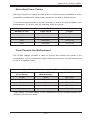
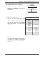
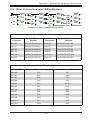
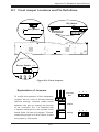
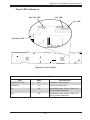
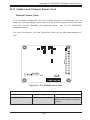
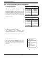
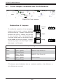
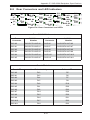
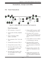
#6. Backplane Main Power Connectors
Backplane
Main Power
4-Pin Connector
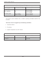
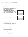
The 4-pin connectors, designated JP10,
JP13, and JP46 provide power to the
Pin#
backplane. See the table on the right for
Definition
1
pin definitions.
2 and 3
4
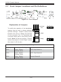
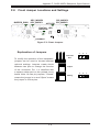
#7/#8/#9. Sideband Headers
+12V
Ground
+5V
Sideband Headers
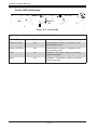
SGPIO is the default mode setting. The
sideband headers are designated JP66,
Pin #
Controller
ID (SB6)
4
SGPIO:
SDOUT;
I2C: Reset
3
GND (SB2)
6
GND (SB3)
5
SGPIO:
SLOAD;
I2C: SDA
8
Backplane
ID (SB7)
7
SGPIO:
SCLOCK;
12C: SCL
10
No Connection
9
No Connection
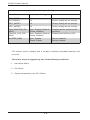
cable. See the table to the right for pin
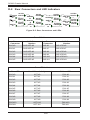
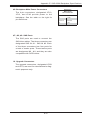
The SAS ports are used to connect the SAS
drive cables. The 12 ports are designated
#0 - #11. Each port is also compatible with
SATA drives.
C-5
Definition
1
erly, you must connect an 8-pin sideband
#10-#21. SAS Ports
Pin #
SGPIO:
SDIN;
I2C:
Backplane
Addressing
JP68, and JP75. For SES-2 to work prop-
definitions.
Definition
2