1
SUPER
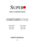
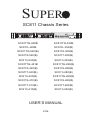
SC811 Chassis Series
SC811TQ-600B
SC811TQ-350B
SC811L-600B
SC811L-350(B)
SC811TQ-520(B)
SC811S-300(B)
SC811S-520(B)
SC811T-300(B)
SC811i-520(B)
SC811i-300(B)
SC811TQ-441B
SC811TQ-280(B)
SC811S-420(B)
SC811S-280(B)
SC811T-420(B)
SC811i-280(B)
SC811i-420(B)
SC811TQ-260(B)
SC811S-410(B)
SC811S-260(B)
SC811T-410(B)
SC811T-260(B)
SC811i-410(B)
SC811i-260(B)
USER’S MANUAL
2.0a
SC811 Chassis Manual
The information in this User’s Manual has been carefully reviewed and is believed to be accurate. The vendor
assumes no responsibility for any inaccuracies that may be contained in this document, makes no commitment
to update or to keep current the information in this manual, or to notify any person or organization of the
updates. Please Note: For the most up-to-date version of this manual, please see our web site at www.
supermicro.com.
Super Micro Computer, Inc. ("Supermicro") reserves the right to make changes to the product described
in this manual at any time and without notice. This product, including software and documentation, is the
property of Supermicro and/or its licensors, and is supplied only under a license. Any use or reproduction of
this product is not allowed, except as expressly permitted by the terms of said license.
IN NO EVENT WILL SUPERMICRO BE LIABLE FOR DIRECT, INDIRECT, SPECIAL, INCIDENTAL,
SPECULATIVE OR CONSEQUENTIAL DAMAGES ARISING FROM THE USE OR INABILITY
TO USE THIS PRODUCT OR DOCUMENTATION, EVEN IF ADVISED OF THE POSSIBILITY OF
SUCH DAMAGES. IN PARTICULAR, SUPERMICRO SHALL NOT HAVE LIABILITY FOR ANY
HARDWARE, SOFTWARE, OR DATA STORED OR USED WITH THE PRODUCT, INCLUDING THE
COSTS OF REPAIRING, REPLACING, INTEGRATING, INSTALLING OR RECOVERING SUCH
HARDWARE, SOFTWARE, OR DATA.
Any disputes arising between manufacturer and customer shall be governed by the laws of Santa Clara
County in the State of California, USA. The State of California, County of Santa Clara shall be the exclusive
venue for the resolution of any such disputes. Super Micro's total liability for all claims will not exceed the
price paid for the hardware product.
California Best Management Practices Regulations for Perchlorate Materials: This Perchlorate warning
applies only to products containing CR (Manganese Dioxide) Lithium coin cells. “Perchlorate Materialspecial handling may apply. See www.dtsc.ca.gov/hazardouswaste/perchlorate”
WARNING: Handling of lead solder materials used in this
product may expose you to lead, a chemical known to
the State of California to cause birth defects and other
reproductive harm.
Manual Revision 2.0a
Release Date: August 26, 2013
Unless you request and receive written permission from Super Micro Computer, Inc., you may not copy any
part of this document.
Information in this document is subject to change without notice. Other products and companies referred to
herein are trademarks or registered trademarks of their respective companies or mark holders.
Copyright © 2013 by Super Micro Computer, Inc.
All rights reserved.
Printed in the United States of America
ii
Preface
Preface
About This Manual
This manual is written for professional system integrators and PC technicians. It
provides information for the installation and use of the SC811 1U chassis. Installation
and maintenance should be performed by experienced technicians only.
This document lists compatible parts available when this document was published.
Always refer to the our Web site for updates on supported parts and configurations.
iii
SC811 Chassis Manual
Manual Organization
Chapter 1 Introduction
The first chapter describes the main features of the SC811 chassis. This chapter
also includes contact information.
Chapter 2 Warning Statements for AC Systems
This chapter discusses warnings, precautions, and system safety. It is recommended that you thoroughly familiarize yourself with the safety precautions in this
chapter before installing and servicing the chassis.
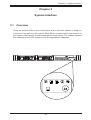
Chapter 3 System Interface
Refer to this chapter for details on the system interface, which includes the functions
and information provided by the control panel on the chassis as well as other LEDs
located throughout the system.
Chapter 4 Chassis Setup and Maintenance
Follow the procedures given in this chapter when installing and removing components, or reconfiguring your chassis.
Chapter 5 Rack Installation
Refer to this chapter for instructions to install the chassis into a rack. Follow the
procedures given in this chapter when installing, removing or reconfiguring your
chassis in a rack environment.
Appendix A Chassis Cables
Appendix B Power Supply Specifications
Appendix C SAS-810TQ Backplane Specifications
Appendix D SATA-810 Backplane Specifications
Note: For information on the CSE-SCA-004 SCSI backplane contact Supermicro's
Technical Support department at www.supermicro.com.
iv
Preface
Contents
Chapter 1 Introduction
1-1Overview.......................................................................................................... 1-1
1-2
Shipping List..................................................................................................... 1-1
1-3
Contacting Supermicro..................................................................................... 1-3
1-4
Unpacking the System..................................................................................... 1-4
1-5
Returning Merchandise for Service................................................................. 1-4
1-6
Where to get Replacement Components......................................................... 1-4
Chapter 2 Standardized Warning Statements for AC Systems
2-1
About Standardized Warning Statements........................................................ 2-1
Warning Definition............................................................................................ 2-1
Installation Instructions..................................................................................... 2-4
Circuit Breaker................................................................................................. 2-5
Power Disconnection Warning......................................................................... 2-6
Equipment Installation...................................................................................... 2-8
Restricted Area................................................................................................. 2-9
Battery Handling............................................................................................. 2-10
Redundant Power Supplies........................................................................... 2-12
Backplane Voltage......................................................................................... 2-13
Comply with Local and National Electrical Codes......................................... 2-14
Product Disposal............................................................................................ 2-15
Hot Swap Fan Warning.................................................................................. 2-16
Power Cable and AC Adapter ....................................................................... 2-18
Chapter 3 System Interface
3-1Overview.......................................................................................................... 3-1
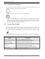
3-2
Control Panel Buttons...................................................................................... 3-2
3-3
Control Panel LEDs......................................................................................... 3-2
3-4
Drive Carrier LEDs........................................................................................... 3-4
SAS/SATA Drives........................................................................................ 3-4
SCSI Drives................................................................................................. 3-4
Chapter 4 Chassis Setup and Maintenance
4-1Overview.......................................................................................................... 4-1
4-2
Removing Power from the System.................................................................. 4-1
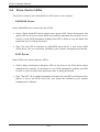
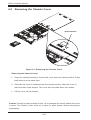
4-3
Removing the Chassis Cover.......................................................................... 4-2
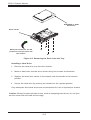
4-4
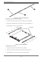
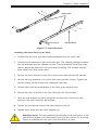
Removing and Installing Hard Drives.............................................................. 4-3
4-5
Installing the Motherboard............................................................................... 4-5
v
SC811 Chassis Manual
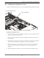
4-6
Installing the Expansion Card.......................................................................... 4-7
4-7
Installing the Air Shroud................................................................................... 4-8
Installation Complete........................................................................................ 4-8
General Maintenance....................................................................................... 4-8
4-8
System Blowers............................................................................................... 4-9
4-9
Power Supply................................................................................................. 4-10
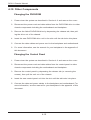
4-10 Other Chassis Components........................................................................... 4-12
Changing the DVD-ROM............................................................................... 4-12
Changing the Control Panel........................................................................... 4-12
Chapter 5 Rack Installation
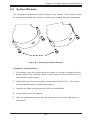
5-1
Preparing for Setup.......................................................................................... 5-1
Choosing a Setup Location.............................................................................. 5-1
Ambient Operating Temperature................................................................. 5-1
Adequate Airflow......................................................................................... 5-1
Circuit Overloading...................................................................................... 5-2
Reliable Ground.......................................................................................... 5-2
Physical Rack Precautions.............................................................................. 5-2
General Server Precautions............................................................................. 5-2
5-2
Rack Mounting Instructions.............................................................................. 5-3
Identifying the Sections of the Rails................................................................ 5-3
Rail Brackets.................................................................................................... 5-3
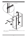
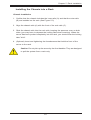
Installing the Chassis into a Rack................................................................... 5-7
Appendix A Cables, Screws, and Other Accessories
A-1Overview..........................................................................................................A-1
A-2
Cables Included with SC811TQ Chassis (SAS/SATA)....................................A-1
A-3
Cables Included with SC811S Chassis (SCSI)................................................A-1
A-4
Cables Included with the SC811T Chassis (SCSI)..........................................A-2
A-5
Compatible Cables...........................................................................................A-2
Alternate SAS/SATA Cables.............................................................................A-2
Extending Power Cables..................................................................................A-3
Front Panel to the Motherboard.......................................................................A-3
A-6
Chassis Screws................................................................................................A-4
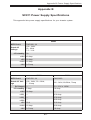
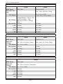
Appendix B SC811 Power Supply Specifications
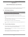
Appendix C SAS-810TQ Safety Guidelines
C-1
ESD Safety Guidelines....................................................................................C-1
C-2
General Safety Guidelines...............................................................................C-1
C-3
An Important Note to Users.............................................................................C-2
C-4
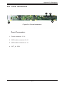
Introduction to the SAS-810TQ Backplane......................................................C-2
vi
Preface
Connectors and Jumpers
C-5
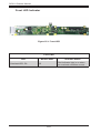
Front Connectors.............................................................................................C-3
Front Components...........................................................................................C-3
C-6
Front Connectors and Pin Definitions..............................................................C-4
C-7
Front Jumper Locations and Pin Definitions....................................................C-6
Explanation of Jumpers...................................................................................C-6
I2C and SGPIO Modes and Jumper Settings..................................................C-7
Front LED Indicators........................................................................................C-8
C-8
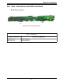
Rear Connectors and LED Indicators..............................................................C-9
Appendix D SATA-810 Backplane Specifications
D-1
ESD Safety Guidelines....................................................................................D-1
D-2
General Safety Guidelines...............................................................................D-1
D-3
An Important Note to Users.............................................................................D-2
D-4
Introduction to the SATA-810 Backplane.........................................................D-2
D-5
Front Connectors.............................................................................................D-3
Front Connectors.............................................................................................D-3
D-6
Front Connector Definitions.............................................................................D-4
D-7
Front Jumper Locations and Pin Definitions....................................................D-5
Explanation of Jumpers...................................................................................D-5
Front LED Indicator..........................................................................................D-6
D-8
Rear Connectors and LED Indicators..............................................................D-7
Rear Connectors..............................................................................................D-7
Rear LEDs........................................................................................................D-8
vii
SC811 Chassis Manual
Notes
viii
Chapter 1
Introduction
1-1Overview
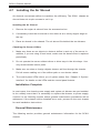
Supermicro’s SC811 1U chassis features a unique and highly-optimized design. The
chassis is equipped with high efficiency power supply in a 1U form factor.
Note: A complete list of safety warnings is provided on the Supermicro web site
at http://www.supermicro.com/about/policies/safety_information.cfm.
1-2 Shipping List
Part Numbers
Please visit the following link for the latest shipping lists and part numbers for your
particular chassis model www.supermicro.com.
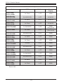
SC811 Chassis Specs
Mode
HDD
I/O Slots
2x SAS/SATA
1x FF
600W
(Gold Level)
2x Fixed
1x FF
600W
(Gold Level)
SC811TQ-520/
SC811TQ-520B
2x SAS/SATA
1x FF
520W
SC811S-520/
SC822S-520B*
2 U320 SCSI
1x FF
520W
2x Fixed
1x FF
SC811TQ-441B
2x SAS/SATA
1x FF
440W
(Platinum Level)
SC811S-420/
SC811S-420B*
2x U320 SCSI
1x FF
420W
SC811T-420/
SC811T-420B*
2x SATA
1x FF
420W
SC811TQ-600B
SC811L-600B
SC811i-520/
SC811i-520B
1-1
Power
Supply
520W
SC811 Chassis Manual
SC811 Chassis Specs
Mode
HDD
I/O Slots
Power
Supply
SC811i-420 /
SC811i-420B*
2x Fixed
1x FF
420W
SC811S-410 /
SC811S-410B*
2x U320 SCSI
1x FF
410W DC
SC811T-410 /
SC811T-410B
2x SATA
1x FF
410W DC
SC811i-410 /
SC811i-410B
2x Fixed
1x FF
410W DC
2x SAS/SATA
1x FF
350W
(Gold Level)
SC811L-350B
2x Fixed
1x FF
350W
(Gold Level)
SC811S-300 /
SC811S-300B*
2x U320 SCSI
1x FF
300W
SC811T-300 /
SC811T-300B
2x SATA
1x FF
300W
SC811i-300 /
SC811i-300B
2x Fixed
1x FF
300W
SC811TQ-280 /
SC811TQ-280B
2x SAS
1x FF
280W
SC811S-280 /
SC811S-280B*
2x U320 SCSI
1x FF
280W
2x Fixed
1x FF
280W
SC811TQ-260 /
SC811TQ-260B
2x SAS/SATA
1x FF
260W
SC811S-260 /
SC811S-260B*
2x U320 SCSI
1x FF
260W
SC811T-260 /
SC811T-260B
2x SATA
1x FF
260W
SC811i-260 /
SC811i-260B
2x Fixed
1x FF
260W
SC811TQ-350B
SC811i-280 /
SC811i-280B
* End of Life
1-2
Chapter 1 Introduction
1-3 Contacting Supermicro
Headquarters
Address:
Super Micro Computer, Inc.
980 Rock Ave.
San Jose, CA 95131 U.S.A.
Tel:
+1 (408) 503-8000
Fax:
+1 (408) 503-8008
Email:
[email protected] (General Information)
[email protected] (Technical Support)
Web
Site:
www.supermicro.com
Headquarters
Address:
Super Micro Computer, Inc.
980 Rock Ave.
San Jose, CA 95131 U.S.A.
Tel:
+1 (408) 503-8000
Fax:
+1 (408) 503-8008
Email:
[email protected] (General Information)
[email protected] (Technical Support)
Web
Site:
www.supermicro.com
Asia-Pacific
Address:
Super Micro Computer, Inc.
3F, No. 150, Jian 1st Rd.
Zhonghe Dist., New Taipei City 23511
Taiwan (R.O.C)
Tel:
+886-(2) 8226-3990
Fax:
+886-(2) 8226-3992
Web
Site:
www.supermicro.com.tw
Technical Support:
Email:
[email protected]
Tel: +886-(2)-8226-3990
1-3
SC811 Chassis Manual
1-4 Unpacking the System
Inspect the box in which the chassis was shipped. If the chassis itself shows damage, file a damage claim with the carrier.
1-5 Returning Merchandise for Service
A receipt or copy of your invoice marked with the date of purchase is required before any warranty service will be rendered. You can obtain service by calling your
vendor for a Returned Merchandise Authorization (RMA) number. When returning to
the manufacturer, the RMA number should be prominently displayed on the outside
of the shipping carton, and mailed prepaid or hand-carried. Shipping and handling
charges will be applied for all orders that must be mailed when service is complete.
For faster service, RMA authorizations may be requested online (http://www.supermicro.com/support/rma/).
Whenever possible, repack the chassis in the original Supermicro carton, using the
original packaging material. If these are no longer available, be sure to pack the
chassis securely, using packaging material to surround the chassis so that it does
not shift within the carton and become damaged during shipping.
This warranty only covers normal consumer use and does not cover damages incurred in shipping or from failure due to the alteration, misuse, abuse or improper
maintenance of products.
During the warranty period, contact your distributor first for any product problems.
1-6 Where to get Replacement Components
Although not frequently, you may need replacement parts for your system. To
ensure the highest level of professional service and technical support, we strongly
recommend purchasing exclusively from our Supermicro Authorized Distributors/
System Integrators/Resellers. A list of Supermicro Authorized Distributors/System
Integrators/Reseller can be found at: http://www.supermicro.com. Click the Where
to Buy link.
1-4
Chapter 2: Warning Statements for AC Systems
Chapter 2
Standardized Warning Statements for AC Systems
2-1 About Standardized Warning Statements
The following statements are industry standard warnings, provided to warn the user
of situations which have the potential for bodily injury. Should you have questions
or experience difficulty, contact Supermicro's Technical Support department
for assistance. Only certified technicians should attempt to install or configure
components.
Read this appendix in its entirety before installing or configuring components in the
Supermicro chassis.
These warnings may also be found on our web site at http://www.supermicro.com/
about/policies/safety_information.cfm.
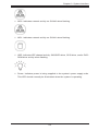
Warning Definition
Warning!
This warning symbol means danger. You are in a situation that could cause bodily
injury. Before you work on any equipment, be aware of the hazards involved with
electrical circuitry and be familiar with standard practices for preventing accidents.
警告の定義
この警告サインは危険を意味します。
人身事故につながる可能性がありますので、いずれの機器でも動作させる前に、
電気回路に含まれる危険性に注意して、標準的な事故防止策に精通して下さい。
此警告符号代表危险。
您正处于可能受到严重伤害的工作环境中。在您使用设备开始工作之前,必须充分
意识到触电的危险,并熟练掌握防止事故发生的标准工作程序。请根据每项警告结
尾的声明号码找到此设备的安全性警告说明的翻译文本。
此警告符號代表危險。
您正處於可能身體可能會受損傷的工作環境中。在您使用任何設備之前,請注意觸
電的危險,並且要熟悉預防事故發生的標準工作程序。請依照每一注意事項後的號
碼找到相關的翻譯說明內容。
2-1
SC811 Chassis Manual
Warnung
WICHTIGE SICHERHEITSHINWEISE
Dieses Warnsymbol bedeutet Gefahr. Sie befinden sich in einer Situation, die zu
Verletzungen führen kann. Machen Sie sich vor der Arbeit mit Geräten mit den
Gefahren elektrischer Schaltungen und den üblichen Verfahren zur Vorbeugung
vor Unfällen vertraut. Suchen Sie mit der am Ende jeder Warnung angegebenen
Anweisungsnummer nach der jeweiligen Übersetzung in den übersetzten
Sicherheitshinweisen, die zusammen mit diesem Gerät ausgeliefert wurden.
BEWAHREN SIE DIESE HINWEISE GUT AUF.
INSTRUCCIONES IMPORTANTES DE SEGURIDAD
Este símbolo de aviso indica peligro. Existe riesgo para su integridad física. Antes
de manipular cualquier equipo, considere los riesgos de la corriente eléctrica y
familiarícese con los procedimientos estándar de prevención de accidentes. Al
final de cada advertencia encontrará el número que le ayudará a encontrar el texto
traducido en el apartado de traducciones que acompaña a este dispositivo.
GUARDE ESTAS INSTRUCCIONES.
IMPORTANTES INFORMATIONS DE SÉCURITÉ
Ce symbole d'avertissement indique un danger. Vous vous trouvez dans une
situation pouvant entraîner des blessures ou des dommages corporels. Avant
de travailler sur un équipement, soyez conscient des dangers liés aux circuits
électriques et familiarisez-vous avec les procédures couramment utilisées pour
éviter les accidents. Pour prendre connaissance des traductions des avertissements
figurant dans les consignes de sécurité traduites qui accompagnent cet appareil,
référez-vous au numéro de l'instruction situé à la fin de chaque avertissement.
CONSERVEZ CES INFORMATIONS.
תקנון הצהרות אזהרה
על מנת להזהיר את המשתמש מפני חבלה,הצהרות הבאות הן אזהרות על פי תקני התעשייה
יש ליצור קשר עם מחלקת תמיכה, במידה ויש שאלות או היתקלות בבעיה כלשהי.פיזית אפשרית
. טכנאים מוסמכים בלבד רשאים להתקין או להגדיר את הרכיבים.טכנית של סופרמיקרו
.יש לקרוא את הנספח במלואו לפני התקנת או הגדרת הרכיבים במארזי סופרמיקרו
2-2
Warning Statements for AC Systems
. تحذٌز!هذا الزهز ٌعًٌ خطز اًك فً حالة ٌوكي أى تتسبب فً اصابة جسذٌة
كي على علن بالوخاطز الٌاجوة عي الذوائز،قبل أى تعول على أي هعذات
الكهزبائٍة
وكي على دراٌة بالووارسات الىقائٍة لوٌع وقىع أي حىادث
استخذم رقن البٍاى الوٌصىص فً ًهاٌة كل تحذٌز للعثىر تزجوتها
안전을 위한 주의사항
경고!
이 경고 기호는 위험이 있음을 알려 줍니다. 작업자의 신체에 부상을 야기 할 수
있는 상태에 있게 됩니다. 모든 장비에 대한 작업을 수행하기 전에 전기회로와
관련된 위험요소들을 확인하시고 사전에 사고를 방지할 수 있도록 표준
작업절차를 준수해 주시기 바랍니다.
해당 번역문을 찾기 위해 각 경고의 마지막 부분에 제공된 경고문 번호를
참조하십시오
BELANGRIJKE VEILIGHEIDSINSTRUCTIES
Dit waarschuwings symbool betekent gevaar. U verkeert in een situatie die
lichamelijk letsel kan veroorzaken. Voordat u aan enige apparatuur gaat werken,
dient u zich bewust te zijn van de bij een elektrische installatie betrokken risico's
en dient u op de hoogte te zijn van de standaard procedures om ongelukken te
voorkomen. Gebruik de nummers aan het eind van elke waarschuwing om deze te
herleiden naar de desbetreffende locatie.
BEWAAR DEZE INSTRUCTIES
2-3
SC811 Chassis Manual
Installation Instructions
Warning!
Read the installation instructions before connecting the system to the power source.
設置手順書
システムを電源に接続する前に、設置手順書をお読み下さい。
警告
将此系统连接电源前,请先阅读安装说明。
警告
將系統與電源連接前,請先閱讀安裝說明。
Warnung
Vor dem Anschließen des Systems an die Stromquelle die Installationsanweisungen
lesen.
¡Advertencia!
Lea las instrucciones de instalación antes de conectar el sistema a la red de
alimentación.
Attention
Avant de brancher le système sur la source d'alimentation, consulter les directives
d'installation.
.יש לקרוא את הוראות התקנה לפני חיבור המערכת למקור מתח
اقر إرشادات التركيب قبل توصيل النظام إلى مصدر للطاقة
시스템을 전원에 연결하기 전에 설치 안내를 읽어주십시오.
Waarschuwing
Raadpleeg de installatie-instructies voordat u het systeem op de voedingsbron
aansluit.
2-4
Chapter 2: Warning Statements for AC Systems
Circuit Breaker
Warning!
This product relies on the building's installation for short-circuit (overcurrent)
protection. Ensure that the protective device is rated not greater than: 250 V, 20 A.
サーキット・ブレーカー
この製品は、短絡(過電流)保護装置がある建物での設置を前提としています。
保護装置の定格が250 V、20 Aを超えないことを確認下さい。
警告
此产品的短路(过载电流)保护由建筑物的供电系统提供,确保短路保护设备的额定电
流不大于250V,20A。
警告
此產品的短路(過載電流)保護由建築物的供電系統提供,確保短路保護設備的額定電
流不大於250V,20A。
Warnung
Dieses Produkt ist darauf angewiesen, dass im Gebäude ein Kurzschlussbzw. Überstromschutz installiert ist. Stellen Sie sicher, dass der Nennwert der
Schutzvorrichtung nicht mehr als: 250 V, 20 A beträgt.
¡Advertencia!
Este equipo utiliza el sistema de protección contra cortocircuitos (o sobrecorrientes)
del edificio. Asegúrese de que el dispositivo de protección no sea superior a: 250
V, 20 A.
Attention
Pour ce qui est de la protection contre les courts-circuits (surtension), ce produit
dépend de l'installation électrique du local. Vérifiez que le courant nominal du
dispositif de protection n'est pas supérieur à :250 V, 20 A.
יש לוודא כי.מוצר זה מסתמך על הגנה המותקנת במבנים למניעת קצר חשמלי
250 V, 20 A-המכשיר המגן מפני הקצר החשמלי הוא לא יותר מ
هذا المنتج يعتمد على معداث الحمايت مه الدوائرالقصيرة التي تم تثبيتها في
المبنى
20A, 250V :تأكد من أن تقييم الجهاز الوقائي ليس أكثر من
2-5
SC811 Chassis Manual
경고!
이 제품은 전원의 단락(과전류)방지에 대해서 전적으로 건물의 관련 설비에
의존합니다. 보호장치의 정격이 반드시 250V(볼트), 20A(암페어)를 초과하지
않도록 해야 합니다.
Waarschuwing
Dit product is afhankelijk van de kortsluitbeveiliging (overspanning) van
uw electrische installatie. Controleer of het beveiligde aparaat niet groter
gedimensioneerd is dan 220V, 20A.
Power Disconnection Warning
Warning!
The system must be disconnected from all sources of power and the power cord
removed from the power supply module(s) before accessing the chassis interior to
install or remove system components.
電源切断の警告
システムコンポーネントの取り付けまたは取り外しのために、
シャーシー内部にアクセス
するには、
システムの電源はすべてのソースから切断され、電源コードは電源モジュールから取り
外す必要があります。
警告
在你打开机箱并安装或移除内部器件前,必须将系统完全断电,并移除电源线。
警告
在您打開機殼安裝或移除內部元件前,必須將系統完全斷電,並移除電源線。
Warnung
Das System muss von allen Quellen der Energie und vom Netzanschlusskabel
getrennt sein, das von den Spg.Versorgungsteilmodulen entfernt wird, bevor es
auf den Chassisinnenraum zurückgreift, um Systemsbestandteile anzubringen oder
zu entfernen.
2-6
Chapter 2: Warning Statements for AC Systems
¡Advertencia!
El sistema debe ser disconnected de todas las fuentes de energía y del cable
eléctrico quitado de los módulos de fuente de alimentación antes de tener acceso
el interior del chasis para instalar o para quitar componentes de sistema.
Attention
Le système doit être débranché de toutes les sources de puissance ainsi que de
son cordon d'alimentation secteur avant d'accéder à l'intérieur du chassis pour
installer ou enlever des composants de systéme.
אזהרה מפני ניתוק חשמלי
!אזהרה
יש לנתק את המערכת מכל מקורות החשמל ויש להסיר את כבל החשמלי מהספק
.לפני גישה לחלק הפנימי של המארז לצורך התקנת או הסרת רכיבים
يجب فصم اننظاو من جميع مصادر انطاقت وإزانت سهك انكهرباء من وحدة امداد
انطاقت قبم
انىصىل إنى انمناطق انداخهيت نههيكم نتثبيج أو إزانت مكىناث الجهاز
경고!
시스템에 부품들을 장착하거나 제거하기 위해서는 섀시 내부에 접근하기 전에
반드시 전원 공급장치로부터 연결되어있는 모든 전원과 전기코드를 분리해주어야
합니다.
Waarschuwing
Voordat u toegang neemt tot het binnenwerk van de behuizing voor het installeren
of verwijderen van systeem onderdelen, dient u alle spanningsbronnen en alle
stroomkabels aangesloten op de voeding(en) van de behuizing te verwijderen
2-7
SC811 Chassis Manual
Equipment Installation
Warning!
Only trained and qualified personnel should be allowed to install, replace, or service
this equipment.
機器の設置
トレーニングを受け認定された人だけがこの装置の設置、交換、
またはサービスを許可
されています。
警告
只有经过培训且具有资格的人员才能进行此设备的安装、更换和维修。
警告
只有經過受訓且具資格人員才可安裝、更換與維修此設備。
Warnung
Das Installieren, Ersetzen oder Bedienen dieser Ausrüstung sollte nur geschultem,
qualifiziertem Personal gestattet werden.
¡Advertencia!
Solamente el personal calificado debe instalar, reemplazar o utilizar este equipo.
Attention
Il est vivement recommandé de confier l'installation, le remplacement et la
maintenance de ces équipements à des personnels qualifiés et expérimentés.
!אזהרה
. להחליף את הציוד או לתת שירות עבור הציוד,צוות מוסמך בלבד רשאי להתקין
يجب أن يسمح فقط للمىظفيه المؤهليه والمدربيه لتزكيب واستبدال أو خدمة هذا الجهاس
경고!
훈련을 받고 공인된 기술자만이 이 장비의 설치, 교체 또는 서비스를 수행할 수
있습니다.
2-8
Chapte