1
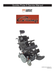
January 2007
©2006 Sunrise Medical
2
Table of Contents
INTRODUCTION
QUICKIE ELECTRONICS SECTION
Introduction ............................................................................4
Tools Required ...............................................................4
Basic Setup ...................................................................5
Multimeter Tutorial ..........................................................6
The Multimeter ........................................................6
The Probes..............................................................6
The Ports.................................................................6
Symbols ..................................................................7
Health and Safety ...........................................................8
Good Working Practices .........................................8
Battery Safety..........................................................8
Battery Chargers .....................................................9
EMI Warnings ..........................................................9
Quickie Electronics by Delphi ..............................................27
Hand Control Types and Functionality .........................27
QR3 – Three Button Rehab Control ......................27
QR 2 Button Mini Hand Control ............................28
QR-ED Quickie Enhanced Display........................28
Delphi Diagnostics Trouble Shooting Chart ..........32
SEATING
Z-Bop Seating System.........................................................33
Back Angle Adjustment ........................................................33
Seat Width Adjustment ........................................................34
Seat Frame Depth Adjustment ............................................35
Seat Depth Adjustment.................................................36
Frame Depth/Seat Depth Position ........................37
POWER BASE SECTION
APPENDIX A
Z-Bop Power Base .............................................................. 11
Batteries ....................................................................... 11
Battery Diagnostics ...............................................12
Battery Types ........................................................13
Accessing the Batteries.........................................14
Changing the Battery ............................................15
Replacing Shrouds .......................................................16
Battery Connectors ...............................................19
Battery Chargers ..........................................................20
Desktop 8 Amp Fully Automatic Charger ..............20
Lightweight Charger ..............................................21
Trouble Shooting ..........................................................21
Motors ..........................................................................22
Checking the Motor Brushes .................................22
Checking Motor Resistance and Continuity ..........22
Motor Removal and Replacement ........................23
The Freewheel Mechanism ...................................25
Drive Wheels ................................................................25
Changing Drive Wheel Assembly ..........................25
Suspension...................................................................26
Acronyms for Delphi ...........................................................39
THE LATEST VERSION OF THE TECHNICAL SERVICE MANUAL CAN BE FOUND AT:
www.sunrisemedical.com
3
©2006 Sunrise Medical
INTRODUCTION
Introduction
Please read and follow instructions in this service manual before attempting to troubleshoot or repair this product
for the first time. If there is anything in this Service Manual that is not clear, or if you require additional technical
assistance, contact Sunrise Medical at 1-800-333-4000. At the prompt, you will be asked to enter your account
number, or if you don’t have your account number, press “#”, then 1 for Customer Services.
Safely troubleshooting and/or repair of this product depends on your diligence in following the instructions within
this manual. Sunrise Medical is not responsible for injuries or damage resulting from a person’s failure to exercise
good judgement and/or common sense.
This Service Manual has been compiled as a troubleshooting guide for the Quickie Z-Bop.
Photographs and content may differ from the actual products in some cases due to changes in specifications and
other factors.
This Service Manual is intended for use by persons with a basic working knowledge and the skills required in
servicing and maintaining Power Wheelchairs. Persons without a General Working knowledge and expertise in the
servicing of this product should not carry out troubleshooting procedures. This can result in problems with future
servicing, and/or damage to the unit.
Parts and configuration or specifications of Products included in this Service Manual are subject to change without
notice.
Tools Required
17.
18.
19.
20.
21.
22.
23.
21.
25.
26.
27.
28.
29.
30.
31.
32.
33.
31.
35.
36.
The following list of tools should enable any task to be
dealt with. Some will only occasionally be needed, but
it is advisable to own or have access to them.
1.
2.
3.
4.
5.
6.
7.
8.
9.
10.
11.
12.
13.
11.
15.
16.
Metric socket set
SAE socket set
Hexagon wrenches, (SAE & metric)
3.5 - 8mm flat screwdriver
No. 0 cross-head screwdriver
No. 1 cross-head screwdriver
No. 2 cross-head screwdriver
Metric combination spanner set 5 - 25mm
SAE combination spanner set 1/8 - 1”
Vice grips
Long nose pliers
Adjustable spanner
Combination pliers
Cir-clip pliers
Hammer, (small & large)
Soft hammer, (rubber, hide or nylon)
©2006 Sunrise Medical
4
Feeler gauges, (metric & SAE)
Utility knife
Pin punches
Electric drill
Drill bits, (metric & SAE)
Torque wrench
Steel engineering rule
Tape measure
Tire pump
Tire pressure gauge
Personal safety gear
Wire strippers/cutters
Tag crimper
Multi-meter
Battery tester
Quickie HHP
Parts manuals & Tech Service manuals
Tire levers
9 inch diagonal cutters
Schrader valve stem puller
INTRODUCTION
Basic Setup
When setting up the components of the chair, complete the following checklist to ensure proper and safe operation
of the equipment.
Check :
□ Are the batteries fully charged?
a. Test battery voltage with D.C. meter across the terminals of batteries. The measurement should be above
12 volts D.C.
b. If not, fully charge the batteries.
□
a.
b.
c.
Are all necessary power components installed and connected ?
Input device (normally Joystick).
Bus cable from Joystick to the controller.
Control Module; for the Z-Bop located under the battery cover.
□
a.
b.
c.
d.
Are all necessary connections fastened or inserted?
Battery connectors to the batteries.
Power harness to battery connectors and controller.
Cable between Joystick and the Control.
Both Motor Connectors to the Control Module.
□ Is the Freewheel Mechanism engaged?
a. With the power off the chair should not move if pushed from behind.
b. If the chair moves when pushed, refer to Freewheel Mechanism section for proper operation.
□ Does 7 bar Display light up when Power On/Off switch is depress?
a. If no - recheck the 4 checks listed above then refer to Diagnostics.
b. If yes – the Power Wheelchair is ready to drive.
5
©2006 Sunrise Medical
©2002
INTRODUCTION
Multimeter Tutorial
MULTIMETER
The Multimeter
The multimeter is one of the most useful tools in the
toolbox. It can be used to check wires, shorts, voltages,
resistance, all manner of electrical circuits. This tutorial
is designed to help clarify the symbols and socket options found on various multimeters.
The Probes
PROBES
Probes connect the meter to the circuit. Simply touch
them to the connections you want to measure and read
the display. Obviously, this depends on how the meter
is set up, and what is being measured.
The Ports
1. The Common Port.
Generally, the black probe plugs in here (negative)
and as the name suggests, it’s the common element to all of the testing circuits. Think of it as the
ground rail.
2. Voltage, Resistance and Continuity port.
This is commonly used option. Connect the red
(positive) probe to this port when using any voltage readings, resistance readings or when checking wire continuity (explained in more detail later
in the tutorial).
3. Current up to 300mA.
This port is used for “counting electrons” in a
circuit, and thus their rate of flow (current being
the flow of electrons). You’ll notice that this side
is “fused”, so that you don’t end up melting the
meter’s circuits.
4. Current up to 10A.
Same as above, except it can take more current,
as the name suggests.
©2006 Sunrise Medical
PORTS
6
INTRODUCTION
Symbols
This section describes the basic symbols used in a typical multimeter.
AC
This symbol means alternating current. Use this when you want to test
something that has AC current running through it. Typically you’d want to test
the voltage of an inverter (for cold cathodes or neons) or a similar device.
DC
This means Direct Current. This is the type of electrical power produced by
a battery. With a battery connector, the black wires) should be connected to
the negative(-) terminal of the battery and should be considered the common
ground. The red wire(s) should be connected to the positive(+) terminal of the
battery and is considered the “hot” lead.
Voltage
This means Voltage or Potential Difference. This measures the potential
difference between the two probes. To measure voltage, connect the positive
probe to a port that is marked “V” or Voltage.
Note: “mV” means millivolts .001 Voltage
Current
Technically, this term is incorrect. It should be “I” but since current is
measured in Amps and the readout value is in amps, the symbol makes
sense. This measures the current that is flowing through the part of the circuit
between the two probes (the meter itself). Typically, you need to plug the
positive terminal into a port marked “A” or Current. You need to put the meter
“In Series” in the circuit to use this feature correctly.
Resistance
This symbol means Resistance and is measured in Ohms. You can use this
setting to measure the resistance between two points; for example across a
piece of wire or a resistor (to check its value). If you don’t have a continuity
check, then this can be used to check for shorts. Any value below 0.05 Ohms
constitutes a short, meaning that whatever the probes are attached to is
connected electrically.
Continuity
A commonly used function. Basically, what it does is put a current through
the two terminals (the same as the Ohm-meter function) and if the resulting
value is within the “contact” range, it will beep. This feature found on some
multimeters enables you to check for shorts without taking your eyes off your
work. Other meters may have a light that turns on when a short is found.
7
©2006 Sunrise Medical
INTRODUCTION
Health and Safety
Good Working Practices
While working on powered mobility products, it is essential to observe good working
practices. Below are a series of safety guidelines and recommendations. Please note that
these precautions are intended to serve only as a guide, not to supersede or replace any
safety statute, NHS or other safety regulations.
General
• Always wear suitable protective clothing when handling batteries.
• Always wear suitable eye protection when drilling or inspecting.
• When safe to do so, wear protective gloves when handling the running gear or
batteries, as these parts are exposed to paths, parks etc.
• If the drive wheels have to be raised off the floor, always use a pair of axle stands
to secure the vehicle.
Battery Safety
•
•
•
•
•
•
•
•
•
•
•
•
•
•
Use extra caution when working with batteries.
Always make sure that the batteries are disconnected from the vehicle before
commencing work.
Always check that the battery charger is disconnected from the vehicle / batteries
before commencing work.
Do not smoke.
Keep batteries away from all sources of ignition.
Do not place objects on the battery tops.
Always try to keep someone within earshot of your work area so that they may
come to your assistance if needed.
Always wear personal protection when handling batteries, including, eye/face
protection and gloves.
Make sure there is easy access to soap and water in case of acid spills.
Avoid touching eyes or unprotected parts of the body while working on batteries.
Remember that non-sealed batteries can contaminate any packaging, housing,
or boxes they may have been transported in so handle all packaging with care,
especially during disposal.
If battery acid should come into contact with bare skin or clothing, be sure to wash
contacted area immediately, using plenty of soap and water. If battery acid enters
the eyes, flush with running cold water for as long as possible while medical help
is being sought.
When the tops of batteries are exposed, take extra care when working on or
around the terminals.
Do not allow metal tools to drop on to or touch the exposed terminals of the
batteries or other exposed connections, as this could cause a short circuit, which
may result in an explosion.
©2006 Sunrise Medical
8
INTRODUCTION
•
•
Remove personal items of jewelry, such as rings, watches, chains etc.
before working on batteries. Such items could cause short circuits resulting
in serious burns.
Batteries are constructed of heavy materials. Therefore moving batteries
requires appropriate lifting techniques. Safety footwear should also be worn.
In addition, disposal of old batteries requires correct procedures. Contact
your local authority for their recommendations.
Battery Chargers
•
•
•
•
•
Remember battery chargers are connected to household current.
Always observe all guidelines and laws relating to electrical equipment.
Never operate the battery charger in wet or damp conditions.
If you think that the charger has been exposed to water or excessive
dampness, do not use it. Return the unit to the dealer/supplier for inspection/
replacement.
If you think the battery charger is defective or is visibly damaged, return the
unit to the dealer/supplier for inspection.
EMI Warnings
•
•
•
•
EMI means electromagnetic (EM) interference (I). EMI comes from radio
wave sources, such as radio transmitters and transceivers. A “transceiver” is
a device that both sends and receives radio wave signals.)
There are a number of sources of intense EMI in our daily environment.
Some of these are obvious and easy to avoid. Others are not, and we may
not be able to avoid them.
Powered wheelchairs, although tested in accordance with EMC guidelines,
may be susceptible to electromagnetic interference (EMI) emitted from
sources such as, radio stations, TV stations, amateur radio (HAM) transmitters,
two-way radios, and cellular phones.
EMI can also be produced by conducted sources or electro-static discharge
(ESD).
What effect can EMI have?
1. EMI, without warning, can cause a power chair to:
• Release its electronic brakes
• Move by itself
• Move in unintended directions.
• If any of these occur, severe injury could result.
2. EMI can damage the control system of a power chair, resulting in a safety
hazard and/or costly repairs.
9
©2006 Sunrise Medical
INTRODUCTION
Sources of EMI
1. Hand-Held Transceivers: The antenna is usually mounted directly on the unit.
These include:
• Citizens band (CB) radios
• “Walkie-talkies”
• Security, fire and police radios
• Cellular phones
• Lap top computers with phone or fax
• Other personal communication devices
Note - These devices can transmit signals while they are on, even if not in use. The
wheelchair should be switched off when not in use.
2. Medium-Range Mobile Transceivers: These include two-way radios used in police
cars, fire engines, ambulances and taxi cabs. The antenna is usually mounted on
the outside of the vehicle.
3. Long-Range Transceivers: These include commercial radio and TV broadcast
antenna towers, amateur (HAM) radios and alarm systems in department stores.
NOTE- The following are Not likely to cause EMI problems: Lap-top computers
(without phone or fax), cordless phones, TV sets or AM/FM radios, CD or tape
players.
EM energy rapidly becomes more intense as you get closer to the source. For
this reason, EMI from handheld devices is of special concern. A person using one
of these devices can bring high levels of EM energy very close to a power chair
without the user’s knowledge.
Immunity level
The level of EM is measured in volts per metre (V/m). Every power wheelchair can
resist EMI up to a certain level. This is called its “immunity level”. The higher the
immunity level, the less the risk of EMI. It is believed that a 20 V/m immunity level will
protect the power wheelchair user from the more common sources of radio waves.
The configuration tested and found to be immune to at least 20 V/m is: Quickie
Rhythm and Groove power wheelchairs with a right-handed mounted joystick system,
18” seat width, 18” seat depth, dual-post height-adjustable armrests, fixed tapered
legrests with one-piece solid footplate and Gp 24 gel cell batteries.
The following dealer installed speciality input devices have an unknown effect on the
immunity level because they have not been tested with the Delphi control system:
• Breath Control (“Sip n Puff”)
• Tri-Switch Head Array
• Proximity Head Array
• Proportional Mini-Joystick/Chin Control
• Buddy Button
• Wafer Board
©2006 Sunrise Medical
10
POWER BASE SECTION
Z-Bop Power Base
Batteries
Safety
If mishandled batteries can be dangerous and hazardous.
•
•
•
•
•
•
All mobility batteries, whether wet type or gel/sealed type, contain lead
and sulfuric acid. Both of these materials are toxic and in the case of
sulfuric acid, highly corrosive. Additionally, when batteries are charged,
they produce hydrogen gas which is “highly” flammable and can cause
explosion. This is why proper handing is mandatory at all times.
Battery explosion - This is frequently the result of too low an acid/electrolyte
level in the battery, which allows high concentrations of hydrogen to build
up. This is possible with all batteries if improper charging or battery failure
occurs, but not common in gel/sealed batteries.
< KEEP SPARKS AND FLAMES AWAY FROM BATTERIES >
Burns - dropping a wrench or screwdriver across battery terminals results
in sparks, and intense heat. Improper assembly of battery boxes or battery
box wiring may short the battery through the wiring and produce a possible
electrical fire.
Electronic damage - batteries that are improperly wired can short out
electronic chair components resulting in expensive repairs.
Pollution - improper disposal of batteries could damage the environment.
All batteries should be disposed of through a reliable battery recycler.
Battery Charge Cycle Illustration
Typical Flooded Battery
Discharge
POS = PbO2
NEG = Pb
ACID = H2SO2
-
+
+
+
+
+
+
+
+
+
+
-
+
-
+
-
+
-
+
-
+
-
+
-
+
-
+
-
+
-
+
POS = PbSO4
NEG = PbSO4
ACID = H2O
-
H2O
H2SO2
Recharge
As battery discharges, the sulfate from the electrolyte forms on the plates.
As battery recharges, the sulfate is driven back into the electrolyte
11
©2006 Sunrise Medical
POWER BASE SECTION
Battery Diagnostics
How Long Should Batteries Last?
An average of 1 to 1.5 years.
Factors that affect battery performance:
• Maintenance - Poor maintenance.
• Charging - Improper charging shortens battery life.
• Chair Components - Malfunctioning electronics, bad motors, electric brakes,
and corroded wiring are just some of the factors that may affect battery life and
performance.
Battery Servicing and Replacement
Automobile batteries, which are used for starting, are tested with a load tester to
assure a high rate of energy production in a short burst.
The voltmeters on load testers are not accurate enough to establish a
state of charge.
Deep-cycle batteries produce energy more slowly and are designed to hold up to
constant discharging and recharging. Testing a deep-cycle wheelchair or scooter
battery requires different procedures than an automobile battery.
A routine for testing deep-cycle batteries should follow these guidelines:
Never replace just one battery at a time. This will create an imbalance when charging
and ultimately damage both batteries.
Check batteries for a voltage difference. A voltage difference of more than .4 volts D.C.
is a true indicator of a bad battery.
Voltage test - A dead battery cannot be effectively tested, yet many people mistakenly
try to do just that. Any battery that reads 11.0 volts or less is technically dead.
To perform any testing, especially a load test:
A. Batteries must be charged
B. The top charge must be taken from fully charged batteries if charge rate has just
finished.
•
•
•
Load Test - This test can only be done on fully charged batteries and can
diagnose one type of problem, an internal short.
Capacity/ Discharge Test - This is the only accurate way to test a deep-cycle
battery for adequate running time. The problem with this test is that it is time
consuming.
Current / Voltage check with a regular interval check - Another way of truly
knowing how much time your battery will last is also time consuming.
©2006 Sunrise Medical
12
POWER BASE SECTION
Battery Types
REMEMBER: IT IS THE RESPONSIBILITY OF THE
INSTALLER TO KNOW WHAT KIND OF BATTERIES
TO INSTALL IN THE CUSTOMER’S WHEELCHAIR!
•
•
•
•
Deep-cycle batteries are designed to be
discharged and recharged on a regular basis.
Starting or automotive type batteries use a rapid
burst of power to start an engine and are quickly
recharged by an alternator or generator. They
are rated by cold cranking amps, a measure that
has no relevance to wheelchair application.
Marine and RV batteries frequently are not
deep-cycle as they are often used for starting
engines.
Only use Deep-Cycle sealed type batteries
in a wheelchair.
U1
Battery Size
• Batteries function as a power wheelchair’s fuel
tank. The larger the group size, the farther the
wheelchair will go.
• Use the size specified by the wheelchair
manufacturer. Never use undersized batteries.
50 Ahr
13
©2006 Sunrise Medical
POWER BASE SECTION
1.
2.
3.
4.
Accessing the Batteries
Pull out the safety pin (A) from the left front seat
post (fig 1.1 ).
Lift up on both front seat latches (fig 1,2).
Tilt the seat back (fig 1.3), slide it forward, and
remove from the base (fig 1.4).
Remove top shroud and unplug motor controller to
expose batteries (fig 1.5).
A
Fig 1.1
General Battery Maintenance
Keep terminals free of corrosion and insure wiring
connections are secure. Check for frayed or loose
contacts.
Fig 1.2
Fig 1.3
Fig 1.4
Fig 1.5
©2006 Sunrise Medical
14
POWER BASE SECTION
Changing the Battery
1. Firmly grasp the red battery connector and pull
apart.
2. Firmly grasp the black battery connector and pull
apart.
3. Firmly grasp the smaller white battery connector
and pull apart.
4. Using provided strap, carefully lift battery from
chair. Rear battery is removed at an angle due to
seat assembly.
Fig 1.6
To install batteries, reverse above procedures. Insure
all wiring is clear of battery compartment before replacing batteries in compartment.
Fig 1.7
Fig 1.8
Fig 1.9
15
©2006 Sunrise Medical
POWER BASE SECTION
Replacing Shrouds
Fairing
• Lift and remove fairing (fig 1.33) (attached with
Velcro).
Fig 1.33
Battery Cover
1. Remove seat (See Accessing Batteries section).
2. Use screwdriver to unlock top shroud.
3. Detach motor controller harness connectors.
4. Lift up and away (fig 1.34).
Fig 1.71
Fig 1.34
Main Shroud Assembly
1. Remove locking pins to release front uprights
(fig 1.35).
Fig 1.35
©2006 Sunrise Medical
16
POWER BASE SECTION
2. Lift and remove front uprights (fig 1.36).
3. Remove locking pins to release rear uprights ( fig
1.37).
4. Lift and remove rear uprights (fig 1.38).
5. Lift and remove rear transit bracket (fig 1.39).
Fig 1.36
Fig 1.37
Fig 1.38
Fig 1.39
17
©2006 Sunrise Medical
POWER BASE SECTION
Replacing Shrouds
6. Unscrew four shroud retaining screws (fig 1.40).
7. Pull front shroud forward slightly (fig 1.41).
8. Lift and remove shroud assembly (fig 1.42).
Fig 1.40
Fig 1.41
Fig 1.42
©2006 Sunrise Medical
18
POWER BASE SECTION
Battery Connectors
The battery connection uses a 2 way connector with a
White Jumper to give the series connection of 24 volt
It has a clearly designated RED and BLACK connector
which connect to the Positive for RED and the Negative for the BLACK with JUMPER (White) joining the
system. The system has a 100 amp non-removable
fuse built into the Cable and a removable 15 amp fuse
for Auxiliary Power.
Fig 1.43
Inspecting the Fuses
Remove caps on each of the two 15 amp fuses and
visually inspect (fig 1.44). Insure there are no breaks
in the fuse material. If continuity is still in doubt, unplug
fuse from holder and check resistance across fuse
blades. Zero resistance indicates a usable fuse. Infinite
resistance indicates a non-usable fuse.
The 100 amp fuses
Fig 1.44
Fuse Wiring Diagram
RED
RED
+
-
YELLOW
BLACK
FRONT
Battery
+
-
BLACK
RED
15A
100A
RED
RED
+
YELLOW
+
100A
Rear
Battery
BLACK
Fig 1.45
19
100A
15A
©2006 Sunrise Medical
POWER BASE SECTION
Battery Chargers
Chargers and Charging
• Use the wheelchair manufacturer’s automatic charger for all routine
charging.
• The best recharge point for deep cycle batteries is roughly at 50%
discharge.
• Never run batteries completely flat [total discharge].
• Do not purchase automotive chargers. They are not designed to charge
deep cycle batteries and will quickly ruin gel/sealed batteries.
• Do not use chargers designed for wet battery charging with gel/sealed
batteries; their charging voltages are different.
Desktop 8 Amp Fully Automatic Charger
DC Output
Connector
Pin 2
Negative
Pin 1
Positive
Pin 3
Inhibit Line
Fig 1.46
Red Light
Off
Steady
Off
Off
Off
Steady
Slow Blink
Fast Blink
Fig 1.47
Green Light
Off
Steady
Slow Blink
Fast Blink
Steady
Off
Off
Off
Function
No AC power or no battery connected
Light test when AC connected
Charging (< 80% charged)
Charging (> 80% charged)
Normal charge completed
Under voltage shut off, < 18.0 volts
Over voltage shutoff, > 33.96 volts
Max timer shutoff, > 16 hours
Fig 1.48
Troubleshooting Tips
1. Check for battery voltage at chair’s charger input .
2. Check for continuity between cable (DC output and connection inside).
3. Check for AC voltage.
1. Check for possible blown fuse.
©2006 Sunrise Medical
20
POWER BASE SECTION
Lightweight Charger
The Lightweight Charger is a switched mode 8 amp
output charger. Because of its compact size it uses a
forced air cooling system. Upon connection to a battery
and AC power, the charger first evaluates the battery’s
state of charge. If the battery is already charged, the
charger goes into standby mode and continuously
monitors the battery’s terminal voltage. If the battery
needs charging the charger begins its charge cycle.
After completing the charge cycle it goes into standby
mode and continuously monitors the battery’s terminal
voltage. If the charger is left connected to the battery, it
will keep the battery “topped off” by beginning a trickle
charge of about 2 amps whenever the terminal voltage
falls below 25.7 volts.
Fig 1.49
Trouble Shooting
The following checklist should help you to troubleshoot
any of the problems with the charger. Make sure to
observe all Safety instructions.
Symptom
LED’s do not
turn on
Yellow LED
blinks 1 time
Yellow LED
blinks 2 times
Yellow LED
blinks 3 times
Yellow LED
blinks 4 times
Fig 1.50
Possible cause
Solution
No Power.
Unit not plugged in.
Bad Outlet.
Blown Fuse internal to charger.
D.C. internal board faulty.
Battery’s rated capacity exceeds charger rating.
Battery may be damaged or old.
Battery’s rated capacity exceeds charger rating
Battery may be damaged or old.
Unit may be damaged if A.C. is removed and
re-applied and does not work.
Battery’s rated capacity exceeds charger rating.
Battery voltage exceeds charger specified
operating range.
Yellow LED
blinks 5 times
Battery charger overheated.
Yellow & Green
LED’s blink
simultaneously
Battery not connected to charger
Too low of voltage less than 6 volts
Reverse Polarity.
21
Try a known good outlet.
Try another charger.
Try another AC cord.
Try another set of batteries.
Try another charger.
Try another set of batteries.
Try another charger.
Try another set of batteries.
Try another charger.
Try a specified set of batteries
Try another charger.
Remove power, wait ten minutes and then
reapply power.
Physically check all connections
Look for shorts or burning smell
If power is re-applied and fault re-occurs
change charger.
Check for good continuity of cable.
Check for good battery
Voltage at charger port Make sure voltage
on meter is reading positive
[no reverse polarity ]
©2006 Sunrise Medical
POWER BASE SECTION
Motors
Checking Motor Resistance and Continuity
Motor Connector
Chair
Z-Bop
Motor
Resistance
0-2 ohms
Brake Solenoid
Resistance
60-65 ohms
Brake Solenoid
Motor
Fig 1.51
Fig 1.53
Fig 1.52
Checking the Motor Brushes
Note: When removing brushes from the motor for
inspection, please note orientation and location of the
brushes as they are removed from the motor (fig 1.54).
The brushes are “burned in” to the commutator and
reinstallation in a location or orientation not matching
the pre-inspection location may negatively affect motor
operation.
Checks:
• How smooth is the brush surface – did it create “C”
shaped groove?
• If there is less than 1/4” brush material left the
Brushes should be replaced.
• How the wire between the coil looks – did it discolor
(fig 1.55)
• Did the Top soldered joint melt (fig 1.56).
• How does the commutator look after the brush has
been contacting the surface (fig 1.57).
Wire between Coil
Fig 1.55
©2006 Sunrise Medical
Brush Assembly
Fig 1.54
Commutator Inspection
Top Solder
Fig 1.56
Fig 1.57
22
POWER BASE SECTION
Motor Removal and Replacement
Disassembly
Note: For ease of disassembly, set the base frame on
a block where all six wheels are at least 1 inch above
the ground.
a. Unwrap the wire looms from the motor and pull the
motor connector out (figure 1.58).
b. Depress the motor connector locking tab and unplug it.
c. Use a 5mm hex key to remove the six mounting
screws (figure 1.59).
d. Hold the motor-wheel assembly and tilt the cog release rod toward the center of the base to get around
the motor mount, then pull the motor-wheel assembly
out through the bottom of the frame.
e. Straighten the lock washer tab of the drive wheel.
f. Use a 17mm deep socket wrench to remove the
drive wheel retention nut, then pull the drive wheel out
from the motor shaft.
fig 1.58
Note: If the drive wheel is difficult to remove, then remove the wheel plate screws (Phillips Head)
Reassembly
a. Perform the reverse of instructions above.
Note: Torque specifications
* Motor mounting screws
15-20 ft-lbs
* Wheel retention nut
35-40 ft-lbs
* Wheel plate screw
15-20 ft-lbs
fig 1.59
Adjustment
Note: There is a suspension bumper on the frame
to limit the motor’s movement (figure 1.60). It also
changes the pre-load on the front caster.
a. Use a 13mm open wrench to loosen or tighten the
jam nut and make the proper adjustment (operator
preference).
b. Install wire tie on back inside corner of gear box.
fig 1.60
23
©2006 Sunrise Medical
POWER BASE SECTION
Disassembly
1. Use a 16mm wrench and 19mm wrench to remove
the motor mount pivot bolt (figure 1.61).
2. Slide the motor mount out from the base frame pivot
bracket.
Reassembly
a. Reverse above instructions.
Hint: Insure the suspension cable is properly seated
on the pulley wheel (fig 1.62).
Note: Torque specifications on the pivot bolt and the
mounting bolt are 40 in-lbs.
Fig 1.61
Fig 1.62
©2006 Sunrise Medical
24
POWER BASE SECTION
The Freewheel Mechanism
Disengage
Pull Cog Release rearward to disengage motor
Engage
Push Cog Release forward to engage motor
Fig 1.63
Drive Wheels
Changing Drive Wheel Assembly
Disassemble:
1. Straighten the lock washer tab of the drive
wheel.
2. Use a 17mm deep socket wrench to remove the
drive wheel retention nut, then pull the drive wheel
out from the motor shaft.
Note: If the drive wheel is difficult to remove, then remove the wheel plate screws (Phillips Head)
Reassembly
Perform the reverse of instructions above.
Note: Torque specifications
* Wheel retention nut
35-40 ft-lbs
* Wheel plate screw
15-20 ft-lbs
Fig 1.64
25
©2006 Sunrise Medical
POWER BASE SECTION
Suspension
Motor Bumper
Note: There is a suspension bumper on the frame
to limit the motor’s movement (figure 1.65). It also
changes the pre-load on the front caster.
a. Use a 13mm open wrench to loosen or tighten the
jam nut and make the proper adjustment (operator
preference).
Rear Caster Bumper
Note: There is a suspension bumper on the rear caster
assembly to limit rocking motion (figure 1.66).
a. Use a 13mm open wrench to loosen or tighten the
jam nut to make the proper adjustment
(operator preference).
Fig
1.66
©2006 Sunrise Medical
26
QUICKIE ELECTRONICS SECTION
Quickie Electronics by Delphi
Hand Control Types and Functionality
Joystick Descriptions:
• All joysticks use a Centered Power On/Off button which have a delay for Power-up
• No delay for Power-down.
• All Joysticks have a Horn which is programmable for volume levels.
• The operation of up or back ( Drive Through Condition) is achieved by deflecting the Joystick in the reverse
direction
• The forward direction will allow the customer to come back to starting position.
QR3 – Three Button Rehab Control
• SUNRISE PART # 020012
• Works with all Quickie Rehab Motor Controls.
• Mode Select, On/Off and Horn Buttons only.
• Program system through programming port
in front of hand control, or through any other
available Bus port.
• Programming via HHP or PCSS.
• LED Indicators for Mode Status, Mode
selection,
• Seating function and Battery SOC.
• Keyless Lock Mode
• Sleep and Power Off Modes
• “Switch” Joystick option with Latched control.
Drive Profile Mode
There are 4 separate Drive Profiles to choose. After
depression of Mode Button push the Joystick in any of
the four directions to choose what Drive Profile to be in.
Fig 2.1
When you select a drive profile, the small light for that
drive profile will glow red to indicate that it has been
selected. After you select a drive profile, the wheelchair automatically goes back into drive mode and any
further movement of the joystick will begin to move the
wheelchair.
Fig 2.2
27
©2006 Sunrise Medical
QUICKIE ELECTRONICS SECTION
QR 2 Button Mini Hand Control
(P/N 020009)
The Delphi Mini-Joystick features comprehensive positioning hardware that greatly enhances the user’s ability
to personalize their fit.
The control box attaches to the armrest.
The mini-joystick comes standard with the Enhanced
Display.
Fig 2.4
QR-ED Quickie Enhanced Display
• (P/N 020024)
• Driving information
• Access to the electronic menu tree
• Remote control of InfraRed (IR) compatible
devices: TVs, DVD players, stereos,X10 household lighting systems, etc.
• Included with all Specialty Control Packages.
Fig 2.5
©2006 Sunrise Medical
28
QUICKIE ELECTRONICS SECTION
Mounting
•
•
QR Hand Controls can be mounted on either
side of the Wheelchair to accommodate Left
Handed and Right Handed Users.
QR Hand Controls must be mounted using
three M5 x 14 button head screws.
12.00
6.00 +- 0.25
12.00
42.00
Fig 2.8
Fig 2.9
Wiring
• Before making any connections to the Hand
Control, disable the Wheelchair by disconnecting
the Batteries and/or elevating the drive wheels.
• Use only Sunrise Medical approved wiring
Harnesses to connect the Hand Control.
• Wiring should be suitably restrained and fastened
to the wheelchair to prevent snagging and to
ensure that there is no strain on connectors.
• Take particular care when routing and securing
cables on moveable structures, such as Tilt, Lift
and Recline etc. Such moving structures have
the potential to crush and shear wiring, causing
potential electrical issues.
• To maintain EMC compliance, ensure that
wires are routed as per Sunrise Medical
recommendations.
Note: bottom two pins 3 & 4 can be used to measure
battery voltage.
Quick Disconnect
Bus Cable
Fig 2.10
Additional Bus Connection/
Programming Connector
Can Bus Pin Outs
Pin Definition
1
CAN Hi
2
CAN Lo
3
+24V
4
Ground
29
©2006 Sunrise Medical
QUICKIE ELECTRONICS SECTION
Programmable Ranges
Menu Item
Drive Profiles
Device
Forward Speed
Reverse Speed
Turning Speed
Forward Acceleration
Reverse Acceleration
Forward Deceleration
Reverse Deceleration
Turn Acceleration
Turn Deceleration
Power
High Speed Torque
Low Speed Torque
Description
Determines number of profiles
Selects Drive input when profile is Active
Determines Fwd Speed settings
Determines Rev Speed settings
Determines Turning Spd settings
Determines Fwd Accel Rate
Determines Rev Accel Rate
Determines Fwd Decel Rate
Determines Rev Decel Rate
Determines Turn Accel Rate
Determines Turn Decel Rate
Determines allowable current for Motor torque limiting
Determines the maximum amount of torque available at the highest speed
Determines the maximum amount of torque available at the lowest speed
Range
1-4
5 - 100
0 – 100
0 - 100
0 - 100
0 - 100
0 - 100
0 - 100
0 - 100
0 - 100
20 - 100
20 - 100
20 - 100
Device
Type of input control utilized : hand control, 3 Button, SCIM1, ECM or compact joystick.
Forward Speed,
The maximum speed setting for the control module and the minimum setting – to drive the chair in the forward
direction.
Reverse Speed
The maximum speed setting for the control module and the minimum setting – to drive the chair in the reverse
direction.
Turning Speed
The maximum speed setting for the control module and the minimum setting – to drive the chair in the left or right
direction.
Accel Fwd & Rev
How quickly the chair reaches the selected speed up to the maximum. Settings are in 1% increments.
Decel – Fwd & Rev
How quickly the chair comes to a stop from forward or reverse directions. Settings are in 1% increments.
Turn Acceleration
How quickly the chair reaches maximum turning speed, or how quickly the chair responds to a turn command. This
parameter is extremely important as to how sensitive the chair is to input device movements and how easy it is for
the user to control the chair.
Turn Deceleration
How quickly the chair comes to a stop from a turn. Also very important in the control of the chair. Settings are 1%
increments.
Torque Limit
Determines amount of demand or current applied to output of control to motors in response to Drive Input commands.
©2006 Sunrise Medical
30
QUICKIE ELECTRONICS SECTION
Power On / Off Options
This button turns the wheelchair control on and off. You can see if the wheelchair control is on by looking at the
lights just under the on/off button. If any of the lights are visible, the control is on.
Keyless Lock Feature
This is a programmable feature that can be Enabled or Disabled – Default Disabled. The lock is engaged by depressing and holding the On/Off switch for a period of greater than 10 seconds and then simultaneously pushing the
joystick forwards.
The lock is disengaged by depressing and holding the On/Off switch for a period of greater than five seconds and
then simultaneously pulling the joystick backwards.
Audio acknowledgment of the lock engaged operation is by sounding the horn for 50ms. Audio acknowledgment
of the lock disengaged operation is by sounding the horn for 50ms three times, with 50ms “spacing” between the
tones.
Battery Diagnostic Threshold
• Battery under-voltage Error Threshold (Range – 13-23 volts - normally set to 16 volts) This is the voltage at
which the control will monitor for a specified period of time and will execute an error of 1 bar flash.
• Battery Voltage Error Period (Range setting of 0 – 100 seconds - normally set to 30 seconds) This is the
period of time in which the control will look at a lower voltage parameter and count a time out – prior to
execution of error
• Battery Voltage Low Warning Threshold (Range setting of 13 – 23 volts - normally set to 18 volts) This is
the voltage at which the control will give a Low Voltage warning normally set higher than the Under-voltage
Error Threshold.
ECM Errors
LED illumination state
Errors are indicated by the LED associated with the
Mode Button Flashing GREEN.
Error Description
ECM Internal Error
Priority *
2
Module Communication Error 3
Battery Under Voltage Error 9
or Battery Over Voltage Error
Invalid System Configuration
Error
1
Drive Lockout External
Source
7
“X” indicates blinking
Battery Operating State of Charge
HCM
BSOC
>80%
70-80%
Any
Any
60-70%
Any
50-60%
Any
40-50%
Any
30-40%
Any
20-30%
Any
31
©2006 Sunrise Medical
QUICKIE ELECTRONICS SECTION
Delphi Diagnostics Trouble Shooting Chart
Symptom
Battery Voltage has
Dropped Lower or Raised
Higher Than Operating
Voltage
Code Flash
Solution
Batteries Depleted
Loose or Disconnected
battery
Bad Cells
Overcharged Batteries
Recharge batteries
Test with Volt Meter
Load Test Batteries
Check Connections
Replace batteries with New Set. Check Battery
Condition for Overcharged You will notice
sides of Batteries are concave (overcharged)
Disconnect Left. Motor Con- 2 bars – every 2 seconds
nection
(Left to Right)
Motor 2 Open Circuit
Check motor connector
Check Armature Resistance
Switch Motor Leads
Replace Brushes
Replace Motor
Disconnect Right. Motor
Connection
3 bars – every 2 seconds
(Left to Right)
Motor 1 Open Circuit
Check motor connector
Check Armature Resistance
Switch Motor Leads
Replace Brushes
Replace Motor
Disconnect of Left or Right
Brake Connection or Brake
over-current
4 bars – every 2 seconds
(Left to Right)
Park Brake 1 or Park Brake Reconnect brake
2 open circuit or Short
Check brake resistance
Circuit
Switch motor leads replace motor
Active Input Not Neutral At
Power-On Error
5 Bars – every 2 seconds
(Left to Right)
Active Input Not Neutral At
Power-On Error
Check to see if client has their hand on remote
Reset Power check integrity of Joystick Gimbal
If bent Replace out
Replace Joystick Module.
Loss of Communication
6 Bars – every 2 seconds
(Left to Right)
Loss of Communication
with Bus Line
Devices on Bus
Check wiring connections
Check all bus connections
Check diagnostic readings Replace components causing failure if constant problem.
Motor Controller Internal
Module Error
7 Bars – every 2 seconds
(Left to Right)
Motor Controller Internal
Module Error
Replace Control module
Check all connections
Motor Controller High Temperature Warning
1 Green (far right green)
Motor Controller High Tem- Stop Chair
perature Warning is TRUE Check Motor Connections
Check Motor resistance (Refer to Section 4)
Check all connections
Replace Control Module
Invalid System Configuration
2 Green (right to left)
Invalid System Configuration Error is TRUE
Check to see if Module is compatible with
system
If using QC control and hooking up non protocol device error will occur
If compatible with system try another control
module unplug Device
Drive Lockout External
Source
3 Green (right to left)
Drive Lockout Source is
True
Connection to source of inhibit such as tilt
system Recline
Charger is Plugged in
Ripples up from 1st LED to Charger Plugged In – InTop LED #7
hibit Circuit
©2006 Sunrise Medical
1 Bar – every 2 seconds
(Left to Right)
Diagnosis
32
Disconnect Charger
Check wiring for Common Pin 2 and Pin 3
short
SEATING
Z-Bop Seating System
Back Angle Adjustment
1. Remove rear back plate through bolt (fig 3.1).
2. Adjust back to desired angle.
3. Replace rear back plate through bolt.
Fig 3.1
33
©2006 Sunrise Medical
SEATING SECTION
Seat Width Adjustment
1. Remove seat.
2. Remove four cross member through bolts (A) and
nuts ( fig 3.2).
3. Adjust width (see chart & fig 3.3).
4. Replace four cross member through bolts.
A
Fig 3.2
Tube Hole Saddle A Saddle B Saddle C
1
10"
11"
12"
2
12"
13"
14"
3
14"
15"
16"
4
16"
17"
18"
Fig 3.3
©2006 Sunrise Medical
34
SEATING SECTION
Seat Frame Depth Adjustment
1. Remove seat
2. Remove four cross member end bolts (A) (fig
3.4).
3. Adjust frame depth (see chart & fig 3.5).
4. Replace four cross member end bolts.
A
A
Fig 3.4
SEAT FRAME DEPTH CROSS MEMBER LOCATION
SHORT (13”-16”)
A&1
STANDARD (15”-18”)
B&2
EXTENDED (17”-20”)
C&3
C
3
B
A
2
1
Fig 3.5
35
©2006 Sunrise Medical
SEATING SECTION
Seat Depth Adjustment
1. Remove forward back plate through bolt (A) and
nut.( fig 3.6).
2. Place bolt (A) in place holder location to prevent
back angle shift ( fig 3.7).
A
Fig 3.6
3. Remove rear back plate through bolt (B) and nut.(
fig 3.7 & fig 3.8).
B
Fig 3.7
Fig 3.8
©2006 Sunrise Medical
36
SEATING SECTION
4. Adjust seat depth per Frame Depth/Seat Depth
Chart ( fig 3.11).
5. Replace rear back plate through bolt and nut (fig
3.9).
6. Replace forward back plate through bolt and nut
( fig 3.10).
Fig 3.9
Fig 3.10
Frame Depth/Seat Depth Position
Frame
Depth
13
14
15
16
17
18
19
20
9
8
7
6
5
Seat
Depth
11
12
13
14
15
16
17
18
Backplate
Position
2&4
3&5
4&6
5&7
6&8
7&9
8 & 10
9 & 11
1
1
2
10
3
11
2
4
3
Fig 3.11
37
©2006 Sunrise Medical
SEATING SECTION
©2006 Sunrise Medical
38
Acronyms for Delphi
Acronym or Term
ACM
BSOC
CAN
CRD
DC
ECM
ED
GUI
HCM
HHP
IR
LED
LCD
MCM
MHCM
PWM
SAE
SCIM
APPENDIX A
APPENDIX A
A
Definition
Attendant Control Module
Battery State Of Charge
Controller Area Network
Customer Requirements Document
Direct Current
Environmental Control Module
Enhanced Display
Graphical User Interface
Hand Control Module
Hand Held Programmer
Infra Red
Light Emitting Diode
Liquid Crystal Display
Motor Control Module
Mini Hand Control Module
Pulse Width Modulated
Society of Automotive Engineers
Specialty Control Input Module
39
©2006 Sunrise Medical
©2006 Sunrise Medical
40