1
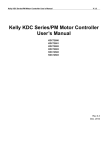
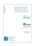
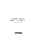
Quickie® Rehab Control
Quickie® Rehab Control
Powered by Delphi®
Owner ’s Manual
QR
Improving People’s Lives
CONTENTS
TA B L E O F C O N T E N T S
1. REHAB CONTROL MODELS OVERVIEW.............................................
A. Quickie Rehab Motor Control ....................................................................
B. Driver Input Types.......................................................................................
C. Displays to Driver........................................................................................
D. Non-Driving Interface Modules...................................................................
E. Customizing the System ..............................................................................
II. WARNINGS AND CAUTIONS ..............................................................
A. EMI (Electromagnetic Interference) ............................................................
B. What is EMI? ................................................................................................
C. What Effect Can EMI Have? ........................................................................
D. Sources of EMI ............................................................................................
E. Distance From EMI Sources........................................................................
F. EMI Immunity Level.....................................................................................
G. Report All Suspected EMI Incidents ............................................................
H. Controller Settings ......................................................................................
I. Safety Check-List.........................................................................................
J. Changes and Adjustments ...........................................................................
K. When Seated in a Parked Wheelchair .........................................................
L. Environmental Conditions ...........................................................................
III. SYSTEM TIMEOUT OR LONG MODE TO TURN OFF POWER..........
IV. OPERATION USING HANDCONTROLS..............................................
A. Keyless Lock Function .................................................................................
B. Auto Mode Enabled or Standby Function ..................................................
C. Operation of Wheelchair Using QR-3: 3 Button Handcontrol ...................
D. Operation of Wheelchair using QR-7 (Europe only): Compact Joystick ....
E. Operation of Wheelchair Using QR-2: Compact Joystick...........................
V. QUICKIE ENHANCED DISPLAY ...........................................................
VI. OPERATION OF WHEELCHAIR USING SPECIALTY
CONTROL MODULE (QR-SCM)............................................................
A. Quickie Enhanced Display ...........................................................................
B. Specialty Input Control................................................................................
C. Power On/Off and Mode Ports...................................................................
D. Input Devices...............................................................................................
VII. OPERATION OF SEATING FUNCTIONS .............................................
A. Operation of Seating Functions Using Handcontrols ..................................
B. Operation of Seating Functions Using Direct Actuator Switch...................
C. Operation of Seating Actuators with Hex Switch and QMAC....................
D. Drive Creep Mode and Drive Lockout .......................................................
E. Function with a Lift Module Present ...........................................................
VIII. OPERATION OF ECM FUNCTIONS .....................................................
IX. TROUBLESHOOTING ............................................................................
A. Display Devices. ..........................................................................................
B. Display Methods ..........................................................................................
C. Coded Display .............................................................................................
D. Textual Display.............................................................................................
E. Diagnostic Messages with Coded Displays .................................................
F. Drive Mode Faults .......................................................................................
G. Power Seating Mode ...................................................................................
H. Diagnostic Messages with Text Displays......................................................
014806 Rev. A
2
3
3
3
3
4
4
4
4
4
4
5
5
5
5
5
5
5
5
6
6
6
6
6
7
8
9
10
10
10
10
10
11
12
12
12
13
13
14
14
14
14
14
14
14
14
14
16
18
I
I . R E H A B C O N T RO L M O D E LS OV E RV I E W
• Can interface and control optional external technologies such
as a mouse emulator for a computer, environmental control
unit or a communication device.
• Acts as the system “hub” for any centralized wheelchair functions
I. REHAB CONTROL MODELS OVERVIEW
The Quickie electronic control system made by Delphi® represents a new means with which to operate powered wheelchairs.
Sunrise Medical has been manufacturing powered mobility devices
for many years and has acquired a vast knowledge of the clinical
needs of those using powered wheelchairs. Delphi is one of the
largest manufacturers of electronics with a worldwide presence
and brings exceptional engineering design and manufacturing
knowledge to powered wheelchair controls. The combination of
these two companies has produced a breakthrough in electronic
controls that exceeds the reliability and durability standards traditionally seen in the powered wheelchair industry.
B. DRIVER INPUT TYPES:
The Quickie QR platform can receive direction or input from a
variety of module types. These inputs are dictated by the unique
needs of the operator. They range from hand function to switch
inputs such as sip n’ puff or head control. This platform is designed
to optimize the function of the operator and ensure safe, simple
and effective driving.
For rehabilitation applications, the family of Quickie electronic
modules made by Delphi begins with the Quickie Rehab (QR) platform. This series of controls are designed with the unique needs of
the individual in mind. These controls are highly customizable and
offer an unmatched level of expansion as needs change over time.
Significant research and development has gone into providing the
Quickie Rehab controls to provide a system that is intuitive while
offering features new to the power wheelchair industry.
1. QR-3 Rehab Joystick or Handcontrol (3 buttons)
• Identified by 3 buttons
• Provides a joystick for those that desire this modality of input
• Provides discrete switches for operator input to control
power on/off, function selector (via permanent keypad
switches and/or via optional phono jacks)
• Provides optional rotary speed dial to let you adjust your
speed
• Provides discrete LED displays for feedback to the driver
through the QR-3
• Provides acoustic output for feedback to the driver and
warning horn
• Can interface with a wide variety of knob choices such as a
goal post and ball.
The electronic control system of a power wheelchair is made of
several modules that work together to provide driving as well as
optional functions such as powered seating, lights, and environmental controls. An overview of this system is shown below:
Your Special
driving
system
Your joystick
Specialty Control
Module – QRSCM
Quickie QR
Motor Control
Module
Powered Seating Systems
2. QR-SCM: Specialty Control Module (SCM)
• Converts an switch type input into commands that the QR
Motor Control Module can interpret
• Provides an interface for special input devices such as Sipand-Puff, ASL, Switch-It, Tash discrete switches, Head
Control, and others
• Provides a lighted display, through the Quickie Enhanced
Display, for feedback to operator as to power status and
mode of operation
Powered
wheelchair
motors
Lights,
Communication
Device,
Computer, etc.
3. QR-2: Compact Joystick (2 buttons)/
Q-AD Attendant Control
• Identified by 2 buttons
• Can be used for chin driving or when a small operator joystick is desired
• Can be used to provide joystick operation for an attendant
override to the primary driver
• Comes standard with discrete switches for power on/off and
mode select
• Provides a lighted display for feedback to operator
• Provides acoustic output for feedback to operator and warning horn
A. QUICKIE REHAB MOTOR CONTROL
MODULE:
This module is similar to the main processing unit of a personal
computer. The QR Motor Control Module takes the input from
you and delivers information and commands to the motors for driving, actuators for powered seating and even to external devices like
a mouse emulator for a computer, environmental control unit or a
communication device.
C. DISPLAYS TO DRIVER:
When a QR-2 joystick module or a QR-SCM is used, the Quickie
enhanced lighted display (QR-ED) acts as the “dashboard” for the
operator. These lights indicate power level, mode, drive profile
number and many additional features.
• Controls the speed and direction of the wheelchair via two
independent direct current (DC) motors and electromechanical brakes
• Estimates the battery charge level and acts as a “gateway”
for battery charging (i.e. the battery and charger each connect directly to the motor control module)
• Can interface and control optional actuator modules for
power assisted seat functions
Enhanced Display Module: QR-ED
• Provides the operator with a clear, easy to see display that
can illustrate text and icons.
• Can provide acoustic output for feedback to driver and
warning horn
3
014806 Rev. A
1
• Ideal for interfacing with external systems such as a mouse
emulator, communication device or a radio frequency controlled ECU system.
• Can have up to two modules which provide four channels.
• When interfacing with infra-red capable devices in your environment, the enhanced display provides integrated Infra-Red
learning for remote control functions
D. NON-DRIVING INTERFACE MODULES:
E. CUSTOMIZING THE SYSTEM:
The Quickie QR platform provides seamless interfacing with a variety of non-driving functions. These functions such as powered
seating operation and alternative switch devices (i.e. mouse emulator, environmental controls, communication devices, etc.) can be
fully controlled right from your input module. This turnkey system
will allow you to select a driving mode, a powered seating mode or
an ECU mode to tell the system what you desire to do. The following modules describe interfacing with non-driving systems:
Like your computer system, the Quickie QR platform has a wealth
of software programming options to ensure that the input and performance is intimately matched to the wants and needs of the
operator. Below you will see the options for programming or customizing the platform:
HandHeld Programmer
• Service tool for the modification of calibration parameters,
and monitoring of system values
Quickie Multi Actuator Control (QR-MAC) Module - optional
• This module is used to control multiple seating functions.
For those times when a single or double powered seating
system is required, then the operation will not require this
module as the function is already built into your operator
input. Instead the QR-MAC is needed for multiple actuator
systems up to 7 actuators.
• Through the QR-MAC, the operator commands the powered seating system fully, with independent control of tilt,
recline, shear reduction, elevating seat and powered elevating legrests.
• Additionally the QR-MAC can allow customizable settings to
your powered seating system (i.e. the range of tilt or recline,
when functions will operate together – recline and powered
legs versus independently.
PC Simulation Program (software only – Available Fall 2006)
• Personal Computer based software for demonstrating the
operational features of the wheelchair system
PC Setup Station (software only – Available Fall 2006)
• Dealer/clinician tool used to customize and troubleshoot the
QR system.
Your Quickie QR wheelchair controls may be configured with a
wide variety of hardware and software options for your individual
needs. Your dealer, clinician or other rehabilitation technical specialist normally does this set up.
Refer to the appropriate sections of this Owner’s Manual for operation of each of these options based on your specific controls configuration. If you are unsure of your specific controls configuration,
please consult your dealer, clinician or call Sunrise Customer Service.
Environmental Control Module (QR-ECM)
• Designed to control nine general purpose relay outputs
• Provides a selectable voltage power supply output
I I . WA R N I N G S A N D C AU T I O N S
2. There are a number of sources of intense EMI in your daily
environment. Some of these are obvious and easy to avoid.
Others are not, and you may not be able to avoid them.
3. Powered wheelchairs may be susceptible to electromagnetic
interference (EMI) emitted from sources such as radio stations, TV stations, amateur radio (HAM) transmitters, twoway radios, and cellular phones.
4. EMI can also be produced by conducted sources or electrostatic discharge (ESD).
II. WARNINGS AND CAUTIONS
A. EMI (ELECTROMAGNETIC
INTERFERENCE)
WARNING
Heed all warnings to reduce the risk of unintended
brake release or chair movement:
1. Beware of the danger from hand-held transceivers. Never
turn on or use a hand-held transceiver while power to your
chair is on. Use extra care if you believe that such a device
may be in use near your chair.
2. Be aware of nearby radio or TV stations, and avoid coming
close to them.
3. If unintended movement occurs or unintended brake release
occurs, turn your chair off as soon as it is safe to do so.
C. WHAT EFFECT CAN EMI HAVE?
WARNING
1. EMI can cause your chair, without warning, to:
• Release its brakes
• Move by itself
• Move in unintended directions
If any of these occurs, it could result in severe injury to you
or others.
2. EMI can damage the control system of your chair. This could
create a safety hazard, and lead to costly repairs.
B. WHAT IS EMI?
WARNING
1. EMI means: electromagnetic (EM) interference (I). EMI
comes from radio wave sources such as radio transmitters
and transceivers. (A “transceiver” is a device that both sends
and receives radio wave signals).
014806 Rev. A
4
II
D. SOURCES OF EMI
WARNING
H. CONTROLLER SETTINGS
WARNING
The sources of EMI fall into three broad types:
Program settings beyond the ability of the rider can
result in serious injury. Consult your health care advisor before you alter settings.
1. Never use the ON/OFF switch to stop your chair except in
an emergency. This will result in an abrupt stop, and may
cause you to fall.
2. To slow or stop your chair, return the joystick to neutral
Be aware that your dealer may need to adjust the controller settings of your chair to reduce the risk of a collision, fall or tip-over.
1. Hand-Held Transceivers: The antenna is usually mounted
directly on the unit. These include: Citizens band (CB)
radios, “Walkie-talkies”, Security, fire and police radios,
Cellular phones, Lap-top computers with phone or fax,
Other personal communication devices
NOTE–
These devices can transmit signals while they are on, even if not in
use.
2. Medium-Range Mobile Transceivers: These include twoway radios used in police cars, fire trucks, ambulances and
taxi cabs. The antenna is usually mounted on the outside of
the vehicle.
3. Long-Range Transceivers: These include commercial radio
and TV broadcast antenna towers and amateur (HAM) radios.
NOTE–
1. Check and adjust the settings every six to twelve months (or
more often, if needed).
2. Consult your supplier to adjust the control settings immediately if you notice any change in your ability to:
• Control the joystick.
• Hold your torso erect.
• Avoid running into objects.
The following are not likely to cause EMI problems: Lap-top computers (without phone or fax), Cordless phones, TV sets or AM/FM
radios, CD or tape players.
E. DISTANCE FROM EMI SOURCES
WARNING
I. SAFETY CHECK-LIST
WARNING
EM energy rapidly becomes more intense as you get closer to the
source. For this reason, EMI from hand-held devices is of special
concern. A person using one of these devices can bring high levels
of EM energy very close to your chair without you knowing it.
Before each use of this chair:
1. Make sure the chair operates smoothly. Check for noise,
vibration, or a change in ease of use. (They may indicate low
tire pressure, loose fasteners, or damage to your chair).
• If you detect a problem, make sure to repair or adjust
the chair. Deferring repair or adjustment could increase
the risk for injury. Your supplier can help you find and
correct the problem.
2. Make sure batteries are charged. Green lights on charge indicator will light up when charge is full. Yellow lights indicate
battery charge level is getting low. Red lights indicate batteries are in immediate need of charging.
F. EMI IMMUNITY LEVEL
WARNING
1. The level of EM energy is measured in volts per meter (V/m).
Every power wheelchair can resist EMI up to a certain level.
This is called its “immunity level”.
2. The higher the immunity level, the less the risk of EMI. It is
believed that a 20 V/m immunity level will protect the power
wheelchair user from the more common sources of radio
waves.
3. The configuration tested and found to be immune to at least
20 V/m.
Individuals with physical limitations requiring the use of a specialty
control input device known not to be immune to 20 V/m, or not
known, should exercise extra care around known sources of EMI.
J. CHANGES & ADJUSTMENTS
WARNING
Never use non-Quickie parts or make changes to
your chair unless authorized by Sunrise. (Doing so
may create a safety hazard).
1. If you modify or adjust this chair it may increase the risk of a
fall or tip-over.
2. Modifications unauthorized by Sunrise constitutes remanufacturing of the wheelchair. This voids the warranty. The rider
then assumes all future liability for the wheelchair.
There is no way to know the effect on EMI if you add accessories
or modify this chair. Any change to your chair may increase the risk
of EMI. Parts from other suppliers have unknown EMI properties.
K. WHEN SEATED IN A PARKED
WHEELCHAIR
WARNING
G. REPORT ALL SUSPECTED EMI
INCIDENTS
WARNING
1. Always turn off your chair when you are parked, even for a
moment. This will prevent:
• Accidental movement from contact with the joystick by
you or others.
• Unintended brake release or movement from EMI
sources. (See Section II-D)
2. Make sure that persons who help you (for example: store
clerks) are aware of the joystick and do not touch it. If they
do, your chair may move suddenly when you do not expect it.
You should promptly report any unintended movement or brake
release. Be sure to indicate whether there was a radio wave source
near your chair at the time.
Contact Sunrise Medical Customer Service Department at
(800) 333-4000.
5
014806 Rev. A
II, III, IV
L. ENVIRONMENTAL CONDITIONS
WARNING
•
•
•
•
Make sure battery cover is secure.
Replace joystick boot if it becomes torn or cracked.
Make sure all electrical connections are secure.
Dry the chair as soon as you can if it gets wet, or if you
use water to clean it.
2. Proceed slowly and use extra care if you must operate your
chair on a wet or slick surface.
• Do so only if you are sure it is safe.
• Stop if one or both main wheels lose traction. If this
occurs, you may lose control of your chair or fall.
• Never operate your chair on a slope or ramp if there is
snow, ice, water or oil film present.
• When in doubt, have someone help you.
3. When not in use, keep your chair in a clean, dry place.
Your chair is not designed for use in a heavy rain
storm, or in snowy or icy conditions.
1. Contact with water or excessive moisture can cause an electrical malfunction. The frame, motors and other chair parts
are not water-tight and may rust or corrode from the inside.
To avoid a chair failure:
• Minimize exposure of your chair to a rain storm or very
wet conditions.
• Never take your chair into a shower, tub, pool or sauna.
• Do not use your chair in fresh or salt water (such as at
the edge of a stream, lake, or ocean).
• Do not use a garden hose or pressure washer to clean
your chair
I I I . S Y S T E M T I M E O U T O R LO N G M O D E TO T U R N O F F P OW E R
set from 0 minutes to 720 minutes. There are two timers. A powersave timer that shuts down the system to conserve power and can
be awakened by a long command (intended for Sip & Puff users)
and a system timeout that shuts down the system completely.
III. SYSTEM TIMEOUT OR LONG MODE
In addition to the on/off buttons, there are two other ways to turn
off the control’s power.
If this feature is enabled, your wheelchair controls will automatically
power off when unused for a long period of time to conserve battery power. This time is programmable by your dealer, and can be
A long mode command or holding the mode button for more than
5 seconds will put the controls into power save mode or suspend.
I V. O P E R AT I O N U S I N G H A N D C O N T RO LS
B. AUTO MODE ENABLED OR
STAND-BY FUNCTION
IV. OPERATION USING HANDCONTROLS
The Quickie Rehab platform comes with the ability to use time to
send the power wheelchair into a waiting mode that allows you to
operate functions other than driving. Programmable by your
provider, this auto mode or stand-by mode occurs when there is
no movement of the joystick or driver input for the programmed
time. This option is available in one or multiple drive profiles. You
will know that you have entered this mode because the small light
next to the mode button will turn red. During this time, you can
choose to drive again or select one of 3 alternative functions: profile select, powered seating mode, or alternative control (ECU)
mode. The forward direction will always return you to active driving and the light will return to green. The left and right turns and
reverse directions are active depending on what you have on your
chair. A left command goes to drive profile select. Once there,
move joystick in direction of profile desired per the drive profile
piechart and the selection is made. Control will return to driving
immediately. The reverse direction will send you to ECM mode
select (only active if an ecm is on the chair – mode light becomes
amber, move joystick in direction of channel desired per the drive
profile select piechart. Once the ECM channel is selected joystick
controls that port until a mode switch is hit. A right command
goes into actuator mode.
A. KEYLESS LOCK FUNCTION
If your wheelchair has the keyless lock function enabled, then you
can use your handcontrol to “lock out” the wheelchair control to
prevent someone else from tampering with the system, and then
unlock it to drive it yourself again.
To lock your control, perform the following sequence – press and
hold the on/off switch for 5 seconds while simultaneously holding
the joystick all the way forward. To unlock your chair, perform the
following sequence press. Hold the on/off switch for 5 seconds
while simultaneously holding the joystick all the way in reverse.
If you ever lock your wheelchair controls and forget the sequence
to unlock, please call your power wheelchair provider.
_____________________________________________
(record phone # here)
014806 Rev. A
6
IV
Battery State of Charge IndicatorGauge
When the green lights are solid and steady, the battery has a high
state of charge. When amber lights are showing, the battery is not
highly charged, but is still charged to some extent. When only the
red lights are showing, the battery charge is low, and you should be
careful not to run out of battery charge or the wheelchair will no
longer operate. Sunrise Medical recommends charging the wheelchair as soon as possible when only the red lights are showing. If
the lights flash, then this indicates a fault and your power chair supplier should be contacted.
Once in actuator mode, right cycles through the options,
forward/reverse operate the actuator, and a mode switch hit is
needed to drive.
Forward
Forward– Active Driving
Left
Left– Drive Profile Select
Reverse
Horn button
When depressed, the horn will sound until the button is released.
Reverse– ECM Mode Select
Mode button
The mode button is used to change driving profiles and to change
the control input device where more than one are fitted. The Mode
button is also used for accessing other wheelchair functions, such as
seating actuators and control of optional Environmental Controls,
based on the functions installed on your chair. A long hold of this
button will also cause your chair to go into suspend mode.
Right
1. Using the mode button to select drive profiles
• When you press the mode button
once, the small light near the mode button will become red, and now the joystick is used to select the drive profile
you want. Move the joystick all the way
forward to select Drive Profile 1, right to
select Drive Profile 2, in reverse to select
Drive Profile 3 and left to select Drive Profile 4. When you
select a drive profile, the small light for that drive profile will
be red to indicate that it has been selected. After you select a
drive profile, the wheelchair automatically goes back into
drive mode and any further movement of the joystick will
begin to move the wheelchair.
Right– Actuator Mode
C. OPERATION OF WHEELCHAIR USING
3 BUTTON HANDCONTROL
On/Off
Battery
Gauge
2. Using the mode button to select seating functions
• If your wheelchair has seating functions installed, you
press the mode button twice to enter seating control mode.
The small light by the mode button will be green when you
are in seating mode. In seating mode, the green lights on the
wheelchair seating icon will indicate which seating actuator is
currently selected. Moving the joystick left or right will
select different seating actuators. While any of these is
selected, moving the joystick forward or reverse will move
the actuator in one direction or the other. Refer to the
power chair manual for more complete directions on seating
actuator control.
Seating
Function
Indicator
Horn
Mode
Button
Drive Profile/ ECM
Select Indicator
3. Using the mode button to select Environmental
Controls or Alternative Controls Mode
• If you press the mode button three times (or twice if your
wheelchair has no seating functions installed), the control will
change into ECM mode and the small light next to the mode
button will be amber. Refer to ECM section later in this manual for operation of ECM devices while in ECM mode.
• Pressing the mode button cycles the control from drive
to drive profile select to seating mode to ECM and then back
to drive in sequence. If your wheelchair does not have seating functions or ECM functions installed, then the control system automatically will skip these modes as the mode button
is selected in sequence. This will also occur if only one of the
four possible drive profiles is active.
If using auto mode or stand-by mode, refer to Section IV-B.
Joystick
The wheelchair is operated through the handcontrol module,
which should be mounted in a convenient location near your hand
while seated in the wheelchair. The picture below shows the joystick and button locations and general purpose for each.
On/Off button
This button turns the wheelchair control on and off. You can see if
the wheelchair control is on by looking at the lights just under the
on/off button. If any of the lights are visible, the control is on.
7
014806 Rev. A
IV
Joystick
The motion of the wheelchair is controlled through the joystick.
Horn button
When depressed, the horn will sound until the button is released.
1. Operation when Handcontrol programmed for
proportional operation:
• Press the joystick in the direction you want the chair to
move. The chair will move faster when the joystick is displaced more. Returning the joystick to the neutral position,
such as by letting go, will cause the chair to stop moving.
Mode button
The mode button is used to switch from drive mode to selection of
drive profile, and to operating other wheelchair functions, such as
seating actuators and control of optional Environmental Controls,
based on the functions installed on your chair. A long command
will cause your power chair to enter suspend mode.
2. Operation when Handcontrol programmed for switch
operation:
• When programmed for switch operation, the Handcontrol
will operate as a, 4 switch input module. Moving the joystick
halfway in a direction will be the same as activation of a
switch. Refer to the later Switch Input Control section of this
Owners Manual for more complete instructions on operation
of the wheelchair using switch inputs.
1. Using the mode button to select drive profiles:
• When you press the mode button
once, the small light near the mode button will become red, and now the joystick is used to select the drive profile
you want. Move the joystick all the way
forward to select Drive Profile 1, right to
select Drive Profile 2, in reverse to select
Drive Profile 3 and left to select Drive Profile 4. When you
select a drive profile, the small light for that drive profile will
be red to indicate that it has been selected. After you select a
drive profile, the wheelchair automatically goes back into
drive mode and any further movement of the joystick will
begin to move the wheelchair.
D. OPERATION OF WHEELCHAIR USING 7
BUTTON HANDCONTROL WITH
LIGHTS AND INDICATORS
(Europe Only)
Battery
Gauge
Seating
Function
Indicator
Mode
Button
On/Off
2. Using the mode button to select seating functions:
• If your wheelchair has seating functions installed, you
press the mode button twice to enter seating control mode.
The small light by the mode button will be green when you
are in seating mode. In seating mode, the green lights on the
wheelchair seating icon will indicate which seating actuator is
currently selected. Moving the joystick left or right will
select different seating actuators. While any of these is
selected, moving the joystick forward or reverse will move
the actuator in one direction or the other. Refer to the later
Seating section of the manual for more complete directions
on seating actuator control.
Assignable
Horn
Drive Profile
Indicator
Assignable
Joystick
3. Using the mode button to select ECM mode:
• If you press the mode button three times (or twice if your
wheelchair has no seating functions installed), the control will
change into ECM mode and the small light next to the mode
button will be amber. Refer to ECM section later in this manual for operation of ECM devices while in ECM mode.
• Pressing the mode button cycles the control from drive
to drive profile select to seating mode to ECM and then back
to drive in sequence. If your wheelchair does not have seating functions or ECM functions installed, then the control system automatically will skip these modes as the mode button
is selected in sequence.
If using auto mode or stand-by mode, refer to Section IV-B.
The wheelchair is operated through the handcontrol module,
which should be mounted in a convenient location near your hand
while seated in the wheelchair. The picture below shows the joystick and button locations and general purpose for each.
On/Off button
This button turns the wheelchair control on and off. You can see if
the wheelchair control is on by looking at the lights just under the
on/off button. If any of the lights are visible, the control is on.
Joystick
The motion of the wheelchair is controlled through the joystick.
Battery
When the green lights are solid and steady, the battery has a high
state of charge. When amber lights are showing, the battery is not
highly charged, but is still charged to some extent. When only the
red lights are showing, the battery charge is low, and you should be
careful not to run out of battery charge or the wheelchair will no
longer operate. Sunrise Medical recommends charging the wheelchair as soon as possible when only the red lights are showing. If
the lights flash, then this indicates a fault and your power chair supplier should be contacted.
014806 Rev. A
1. Operation when Handcontrol programmed for
proportional operation:
• Press the joystick in the direction you want the chair to
move. The chair will move faster when the joystick is displaced more. Returning the joystick to the neutral position,
such as by letting go, will cause the chair to stop moving.
2. Operation when Handcontrol programmed for switch
operation:
• When programmed for switch operation, the
Handcontrol will operate as a, 4 switch input module,
8
IV
depending on how the system was set up. Moving the joystick halfway in a direction will be the same as activation of a
switch. Refer to the later Switch Input Control section of
this Owners Manual for more complete instructions on operation of the wheelchair using switch inputs.
Horn Function
The horn is accessed through the Driver menu.
Mode button
The mode button is used to switch from drive mode to selection of
drive profile, to seating functions and to control of Environmental
Controls, depending on the functions installed on your chair.
Headlamps button
Press this button to turn the headlamps on and off. The small light
next to the button will be lit when the headlamps are on. You
must press a second time to turn this function off.
1. Determining which drive profile is active:
• When you first turn on the wheelchair controls, the small
light by the mode button will be red, and then turn off for
1.5seconds followed by a flash once for drive profile 1, twice
for drive profile 2, three times for drive profile 3 or four
times for drive profile 4. This is also shown in the upper left
hand corner of the QR-ED screen which displays the number
of drive profile which is active.
Hazard Lights button
Press this button to turn the hazard lights on and off. The small
light next to the button will flash when the hazard lights are on.
You must press a second time to turn this function off.
Right Turn Indicator
Press this button to turn the turn indicator lights on and off. The
small light next to the button will flash when the Right Turn lights
are on. You must press a second time to turn this function off.
2. Using the mode button to select drive profiles:
• When you press the mode button
once, the QR-ED will cycle from the
active drive screen to the Driver Menu
screen. The first item on the Driver
Menu is Drive Profile Select. A right
command will send you into the Drive
Profile Select Screen, at which point an
input command in the direction shown will select that profile.
As soon as a selection is made, the screen will return to
active ready to drive.
Left Turn Indicator
Press this button to turn the turn indicator lights on and off. The
small light next to the button will flash when the Left Turn lights are
on. You must press a second time to turn this function off.
E. OPERATION OF WHEELCHAIR USING
QR-2 COMPACT JOYSTICK
On/Off
3. Using the mode button to select seating functions:
• If your wheelchair has seating functions installed, you
press the mode button the QR-ED will cycle from the active
drive screen (shown below) to the Driver Menu screen
(shown below). On the driver menu will be the powered
seating options available on your chair. A right command will
send you into the powered seating function. A mode command will return you to ready to drive. While any of these
functions are selected, moving the joystick forward or
reverse will move the actuator in one direction or the other.
Refer to the later Seating section of the manual for more
complete directions on seating actuator control. An audible
acknowledgement is given each time the actuator is changed.
If using auto or stand-by mode, refer to Section IV-B.
Mode
button
The wheelchair is operated through the handcontrol module,
which should be mounted in a convenient location while seated in
the wheelchair. When used as the primary driver control, the QR2 should be used with the QR-ED to provide feedback to the user.
The picture below shows the joystick and button locations and
general purpose for each.
Joystick
The motion of the wheelchair is controlled through the joystick.
1. Operation when Handcontrol programmed for
proportional operation:
• Press the joystick in the direction you want the chair to
move. The chair will move faster when the joystick is displaced more. Returning the joystick to the neutral position,
such as by letting go, will cause the chair to stop moving.
On/Off button
This button turns the wheelchair control on and off. You can see if
the wheelchair control is on by looking at the lights next to the
on/off button. If any light is visible, the control is on.
2. Operation when Handcontrol programmed for switch
operation:
• When programmed for switch operation, the Handcontrol
will operate as a 4 switch input module. Moving the joystick
halfway in a direction will be the same as activation of a
switch. Refer to the later Switch Input Control section of this
Owners Manual for more complete instructions on operation
of the wheelchair using switch inputs.
Battery Gauge
While driving, the small light near the On/Off button will indicate
the battery state of charge. Green indicates high battery charge,
amber indicates mid battery charge, red indicates low battery
charge and flashing red indicates very low battery charge. If used
with a Quickie Enhanced Display, then the battery gauge will be
shown on the display screen.
9
014806 Rev. A
V, V I
V. Q U I C K I E E N H A N C E D D I S P L AY – U S E R M E N U A N D NAV I G AT I O N
The general menu structure is
PROGRAM –
Used to enable/disable features and set operating parameters for various functions
V. QUICKIE ENHANCED DISPLAY
The menu visible in the Quickie Enhanced Display is used to navigate from one wheelchair function to another. The “Driver Menu”
is a customized group of menu selections that was programmed for
you when your wheelchair was set up. The wheelchair functions
that you use most frequently should be the functions placed in your
user menu at setup.
All the menu items are available in the Operate menu. To get from
the Driver Menu to the Operate menu, go to the top of the Driver
Menu and execute a long left command (more than 3 seconds).
OPERATE –
Used to operate wheelchair functions
MONITOR –
This section of the menu is used to monitor
various operating characteristics of the wheelchair. This is normally used in conjunction with
set up and maintenance by a dealer.
INFORMATION – This section of the menu is used to display
module information such as model number,
serial number, hardware version, software version, etc. This section of the menu is normally
used by the dealer in maintenance.
Menu navigation in either the Driver Menu or the Main Menu is
similar to using Windows Explorer on your personal computer.
Navigation of the menu is done by using the following commands,
which have the following action associated with them:
FAULTS –
FORWARD – takes you up the menu.
REVERSE – takes you down the menu.
LEFT –
takes you up one level in the menu.
RIGHT –
takes you down one level in the menu or activates
the highlighted function.
ESCAPE –
takes you back to drive mode.
This section of the menu is used to display fault
for troubleshooting and maintenance by the
dealer.
For more information on the Quickie Enhanced Display, refer to
the Quickie Enhanced Display Manual.
V I . O P E R AT I O N O F W H E E LC H A I R U S I N G S P E C I A LT Y
C O N T RO L I N P U T M O D U L E ( Q R - S C M )
B. SPECIALTY INPUT CONTROL
VI. OPERATION OF WHEELCHAIR USING QR-SCM
General
The Quickie QR-SCM is used to take the signals from your specialty input and translate them to QR motor controller. The following
input types are possible:
If your wheelchair is set up to operate using a specialty input
device, such as breath control, head array or tray switches, then
the input device is used to control the wheelchair functions rather
than the handcontrol.
• 4 Axis Proportional
• 3 Axis Proportional
• 4 Sw
• 3 Sw
• 2 Sw
• 1 Sw
• Sip & Puff – 4 Pressure
• Sip & Puff 2 Pressure
• Sip & Puff 2 Pressure with 2 Sw
See the detailed operations for these drive methods in
Section VI-D.
DB9
Connector
NOTE:
SNP
Sensor
Jacks for Power
and Mode
all of these Inputs can be used in conjunction with:
On/Off Switch
Mode Switch
Escape Timeout
Latched Methods
A. QUICKIE ENHANCED DISPLAY
C. POWER ON/OFF AND MODE PORTS
It is recommended that users of specialty input devices have an
Enhanced Display installed in order for you to know the state of
your wheelchair controls although operation of the QR-SCM is possible without. This manual assumes that a Quickie Enhanced
Display is provided with your specialty controls.
On each QR-SCM there are 2 jacks for a power on/off switch and a
mode switch. These ports can except any 1/8” standard mechanical
ability switch.
On/Off Control
If installed, this button turns the wheelchair control on and off. You
can see if the wheelchair control is on by looking at the lights just
under the on/off button. If there is a visible screen on the ED, then
the wheelchair power is on.
For instructions regarding additional features of the Enhanced
Display, please refer to the Quickie Enhanced Display manual.
014806 Rev. A
10
VI
Escape Methods– Means to change from driving to non-driving functions.
1. Mode Switch
If installed, the mode button is used to toggle between Drive
Mode and the Menu Mode.
2. Escape Timeout
If escape timeout is enabled on your wheelchair, then if you
do not issue any commands, the controls will automatically
escape after a pre-set length of time. Escape timeout will
toggle between drive mode and the QR-ED driver menu.
transitions may be performed by allowing the control
to timeout or use the stand-by mode to progress to the
next mode if your control is so programmed.
b. 3 Axis
A 3-axis proportional input device may be configured
with a separate on/off button and/or may be configured
with a separate mode button, or the mode transitions
may be performed by allowing the control to timeout to
the next mode if your control is so programmed.
The motion of the wheelchair is controlled through
the 3-axis input. To toggle between forward and
reverse directions, execute a short forward command.
If your controls have “FWD/REV MODE” enabled
then the chair will automatically toggle between forward and reverse direction on a pre-set programmable time cycle.
Suspend Activation
If it is desired to use only one switch, a long mode command or
pressing the mode button for more than 5 seconds will cause the
chair to power on. A long mode command when the chair is on
will cause the control to switch off.
Latched Method
Switched Input Devices can be set up in latched, cruise or steppedcruise operation. Latched, Cruise and Stepped Cruise operation
apply only to driving the wheelchair forward or reverse, not to
steering inputs which always operate to steer for as long as the
steering input command is given by the user. Additionally, your
wheelchair can have only the forward or the reverse direction programmed for latched, Cruise or Stepped Cruise operation with the
opposite direction in non-latched mode.
2. Switched
Switched input devices include breath control, switched head
arrays, tray switches etc. Inputs to the wheelchair control using
switches is different depended on the number of switches installed
and set up on your wheelchair. Configurations of switches include
4 switch, 3 switch, 2 switch, 1 switch, and sip & puff control. Since
operation of the wheelchair only depends on the number of
switches installed and set up, not of the input device itself, each
switch configuration is described separately below.
1. Single Speed
In Single Speed latched mode, when a forward or reverse
switch command is executed, the wheelchair will move at a
pre-set speed until the opposite directional command is
given. The opposite directional command will cause the
wheelchair to stop.
2. Step
In Stepped-Cruise mode, when a forward or reverse command is executed, each time the same-direction command is
executed, the wheelchair will accelerate to a somewhat higher
speed and when the opposite direction command is executed
the wheelchair will decelerate to a somewhat slower speed in
original direction. To stop the wheelchair in Stepped-Cruise
mode, a long opposite direction command is given.
3. Cruise
In Cruise mode, when a forward or reverse command is executed, the wheelchair will gradually accelerate as long as the
command is being executed. Then when the switch is
released the wheelchair will proceed at that constant speed
until an opposite command is executed. An additional samedirection will increase speed in that direction. The opposite
directional command will cause the chair to slow down until
the opposite command is released. Additional oppositedirection commands will cause further decreased speed.
a. 4 Sw
A 4-Switch input device may be configured with a separate on/off button and/or may be configured with a
separate mode button, or the escape timeout may be
used if enabled. Alternatively, you may use two short
forward commands in sequence to escape.
The motion of the wheelchair is controlled through
the 4-switch discrete input device.
If you press two adjacent directions simultaneously, the
wheelchair will move diagonally in those two directions. While driving forward or reverse, if you simultaneously give the right or left command for a period,
the chair will continue moving forward or reverse, but
will turn left or right as long as the adjacent direction
command is given in order to steer.
b. 3 Sw
The motion of the wheelchair is controlled through
the 3-switch discrete input device.
If you execute two adjacent direction commands
simultaneously, the wheelchair will move diagonally in
those two directions. While driving forward or reverse,
if you simultaneously give the right or left command for
a period, the chair will continue moving forward or
reverse, but will turn left or right as long as the adjacent
direction command is given in order to steer.
Toggle between forward and reverse direction by executing a short forward command or, if enabled, allowing
the wheelchair to timeout to toggle direction.
D. INPUT DEVICES
There are two basic types of input devices, proportional and switched,
and operation of the wheelchair is different for each of these.
1. Proportional
Proportional devices are inputs, such as a joystick, which move the
wheelchair faster or slower depending on how much you move the
input device. For example, if you move the joystick all the way forward the chair will go faster than if you only move it part way forward.
c. 2 Sw
The motion of the wheelchair is controlled through
the 2-switch discrete input device.
A forward command is a short left switch closure, followed by another left switch closure. A reverse command is a short right switch closure, followed by
another right switch closure. In unlatched mode, the
a. 4 Axis
A 4-direction proportional input device may be configured with a separate on/off button and/or may be configured with a separate mode button, or the mode
11
014806 Rev. A
VI, VII
chair will continue forward or reverse as long as the
second switch closure is maintained. When in
unlatched mode, you must stop driving forward or
reverse to turn.
3. Sip & Puff
a.
d. 1 Sw
Single switch is always used in scanning mode.
Scanning operation can be set up as 8-direction or 4
direction. 4 direction can be set up either in 5-step or
7-step sequence.
• 4 step– The scan selections will automatically
change every few seconds (this is programmable)
according to a pre-set sequence of selections.
When the desired selection is visible in the ED,
the single switch closure will select the function.
For a 5-step sequence, the selections are – forward, right, reverse, left and escape in order.
• 8 Step– The scan selections will automatically
change every few seconds (this is programmable)
according to a pre-set sequence of selections.
When the desired selection is visible in the ED,
the single switch closure will select the function.
For a 5-step sequence, the selections are – forward, forward-right, right, reverse-right, reverse,
escape, reverse-left, left, forward-left, and escape
in order. After selection of the desired function,
the scanner keeps scanning in the same order.
•
•
•
•
4 Pressure– Sip & puff commands.
Hard puff is forward.
Hard sip is reverse
Soft puff is right
Soft sip is left
b.
•
•
•
•
•
2 Pressure– Sip & puff commands.
Short double puff is forward
Short double sip is reverse
Sip is left
Puff is right
Double sip is escape
c. 2 Pressure with 2 Sw
While driving forward or reverse, the two switch input
buttons steer the wheelchair in the left or right directions. The wheelchair will steer in the indicated direction for as long as the button is pressed, and will stop
steering in that direction when the button is released.
Sip & puff commands.
• Puff is forward
• Sip is reverse
• Left switch is left
• Right switch is right
V I I . O P E R AT I O N O F S E AT I N G F U N C T I O N S
the joystick in the reverse direction will move the seating actuator in
the opposite direction. Releasing the joystick will NOT stop movement of the seating actuator. Any additional movement of the joystick will stop movement of the seating actuator.
VII. OPERATION OF SEATING FUNCTIONS
A. OPERATION OF SEATING FUNCTIONS
USING HANDCONTROLS
B. OPERATION OF SEATING FUNCTIONS
USING DIRECT ACTUATOR SWITCH
When using a handcontrol, first enter Seating Mode using the Mode
button as described for your Handcontrol model. When in Seating
Mode, movement of the joystick to the left or right will select
which actuator to move, and movement of the joystick forward or
reverse will actually move the actuator. The Seating Functions can
be set up in latched or unlatched mode.
If a direct actuator switch is installed on your wheelchair, then you
can still operate the seating actuators from the handcontrol module
or the SCIM as described above for your specific control model.
However, the seating actuators can also be operated, even while
driving the wheelchair with the joystick. Direct actuator switches
can be used to operate up to two seating functions.
One seating actuator (Latched mode not enabled). Note: all seating
functions are set up as latched or non-latched as a group. If you
do not know whether latched mode is enabled for your wheelchair,
please ask the dealer or technician who programmed the controls.
While one of the Seating Functions is selected, move the joystick
forward to move the seating actuator in one direction and release
the joystick to stop. Move the joystick in reverse to move the
seating actuator in the opposite direction.
Operation of seating actuators with a direct actuator switch is different depending on whether you have one or two actuator functions and whether latched mode is enabled or disabled.
One seating actuator (Latched mode not enabled). Note: all seating
functions are set up as latched or non-latched as a group. If you
do not know whether latched mode is enabled for your wheelchair,
please ask the dealer or technician who programmed the controls.
Move the Direct Actuator Switch forward to move the seating
actuator in one direction and release Direct Actuator Switch to
stop. Move the Direct Actuator Switch in reverse to move the
seating actuator in the opposite direction.
One Seating actuator (Latched mode enabled). Note: all seating
functions are set up as latched or non-latched as a group. If you do
not know whether latched mode is enabled for your wheelchair,
please ask the dealer or technician who programmed the controls.
While one of the Seating Functions is selected, move the Direct
Actuator joystick forward to move the seating actuator in one direction. Releasing the Direct joystick will NOT stop movement of the
seating actuator. Any additional movement of the joystick in any
direction will stop movement of the seating actuator. Movement of
014806 Rev. A
One Seating actuator (Latched mode enabled). Note: all seating
functions are set up as latched or non-latched as a group. If you do
not know whether latched mode is enabled for your wheelchair,
12
VII
C. OPERATION OF SEATING ACTUATORS
WITH HEX SWITCH
AND QMAC
please ask the dealer or technician who programmed the controls.
Move the Direct Actuator Switch forward to move the seating
actuator in one direction. Releasing the Direct Actuator Switch will
NOT stop movement of the seating actuator. Any additional
movement of the Direct Actuator Switch will stop movement of
the seating actuator. Movement of the Direct Actuator Switch in
the reverse direction will move the seating actuator in the opposite
direction. Releasing the Direct Actuator Switch will NOT stop
movement of the seating actuator. Any additional movement of the
Direct Actuator Switch will stop movement of the seating actuator.
If your wheelchair is equipped with an independent Hex Switch then
you can operate up to six seating actuators independently from the
joystick or from the SCIM input device. The hex switch will normally be mounted in a convenient location for operation by hand.
You can be driving the wheelchair and still operate seating functions
at the same time using the Hex Switch.
Two seating actuators(Latched mode not enabled). Note: all seating
functions are set up as latched or non-latched as a group. If you
do not know whether latched mode is enabled for your wheelchair,
please ask the dealer or technician who programmed the controls.
The Direct Actuator Switch is used to operate either Seating actuator 1 by moving it in the forward direction or Seating actuator 2 by
moving it in the reverse direction.
Operation of seating actuators using the Hex Switch is different
depending on how many actuators are on your wheelchair and
whether latched mode is enabled. Each direction of the Hex
Switch joystick and each of the two buttons can be set up to operate a different seating function.
Operation of Seating Functions when Latched mode is not
enabled.
Note: all seating functions are set up as latched or non-latched as a
group. Individual seating functions cannot be set up as latched
while others are unlatched. If you do not know whether latched
mode is enabled for your wheelchair, please ask the dealer or technician who programmed the controls. The first switch closure of a
seating function switch using the Hex Switch will move the seating
actuator in one direction for as long as the switch is closed.
Releasing the switch will stop movement of the actuator. The second switch closure of the same switch will select the opposite
direction for that seating function. The third switch closure will
move that actuator in the opposite direction for as long as the
switch is closed. Releasing the switch will stop movement of the
actuator.
Move the Direct Actuator Switch forward to move seating actuator
1 in the one direction and release to stop. Move the Direct
Actuator Switch forward again to move seating actuator 1 in the
opposite direction and release to stop.
CAUTION: If you don’t remember the last direction the actuator was moving
when last used, then you might move in an unintended direction.
Move the actuator slowly to avoid an unwanted movement.
Move the Direct Actuator Switch in reverse to move seating actuator 2 in the one direction and release to stop. Move the Direct
Actuator Switch in reverse again to move seating actuator 2 in the
opposite direction and release to stop.
CAUTION: If you don’t remember the last direction the actuator was moving
when last used, then you might move in an unintended direction.
Move the actuator slowly to avoid an unwanted movement.
CAUTION: If you don’t remember the last direction the actuator was moving
when last used, then you might move in an unintended direction.
Move the actuator slowly to avoid an unwanted movement.
Two seating actuators (Latched mode enabled). Note: all seating
functions are set up as latched or non-latched as a group. If you do
not know whether latched mode is enabled for your wheelchair,
please ask the dealer or technician who programmed the controls.
The Direct Actuator Switch is used to operate either Seating actuator 1 by moving it in the forward direction or Seating actuator 2 by
moving it in the reverse direction.
Operation of Seating Functions when Latched mode is enabled.
Note: all seating functions are set up as latched or non-latched as a
group. Individual seating functions cannot be set up as latched while
others are unlatched. If you do not know whether latched mode is
enabled for your wheelchair, please ask the dealer or technician
who programmed the controls. The first switch closure of a seating function switch using the Hex Switch will move the seating
actuator in one direction, and releasing the switch will not stop the
actuator movement. To stop the actuator movement, press any
Hex Switch button or move the Hex Switch joystick in any direction. The next switch closure of the same switch will select the
opposite direction for the same seating function.
Move the Direct Actuator Switch forward to move seating actuator
1 in one direction. Releasing the Direct Actuator Switch will NOT
stop movement of actuator 1. To stop movement of actuator 1,
move the Direct Actuator Switch in any direction. Move the
Direct Actuator Switch forward again to move seating actuator 1 in
the opposite direction. Releasing the Direct Actuator Switch will
NOT stop movement of actuator 1. To stop movement of actuator 1, move the Direct Actuator Switch in any direction.
CAUTION: If you don’t remember the last direction the actuator was moving
when last used, then you might move in an unintended direction.
Move the actuator slowly to avoid an unwanted movement.
CAUTION: If you don’t remember the last direction the actuator was moving
when last used, then you might move in an unintended direction.
Move the actuator slowly to avoid an unwanted movement.
Move the Direct Actuator Switch forward to move seating actuator
1 in one direction. Releasing the Direct Actuator Switch will NOT
stop movement of actuator 2. To stop movement of actuator 2,
move the Direct Actuator Switch in any direction. Move the Direct
Actuator Switch forward again to move seating actuator 2 in the
opposite direction. Releasing the Direct Actuator Switch will NOT
stop movement of actuator 1. To stop movement of actuator 2,
move the Direct Actuator Switch in any direction.
D. DRIVE CREEP MODE AND DRIVE
LOCKOUT
When using seating functions such as tilt, recline or seat lift, the
wheelchair may become unstable if you drive too fast while the
seating is in a tilted, reclined or lifted position. For this reason, if
your seating system is in a position that might cause instability, the
controls will automatically cause the wheelchair to enter “creep
mode” where only driving slowly is allowed, or will automatically
lock out the drive function so the chair may not be driven as long
as the seating system is in that position. Returning your seating
CAUTION: If you don’t remember the last direction the actuator was moving
when last used, then you might move in an unintended direction.
Move the actuator slowly to avoid an unwanted movement.
13
014806 Rev. A
VII, VIII, IX
position will automatically enable normal driving function. While in
creep mode or drive lock out, the green lights on the seating icons
on handcontrols will all flash or the ED will indicate that you are in
either drive lockout or creep mode.
down position. You should always operate your lift only on flat
level ground free of obstructions. Serious injury can occur if driving
on sloped terrain or while climbing an obstacle with the seat elevated. If combined with a power tilt or power recline system, then
the tilt or recline can only be used to a specific angle while the lift is
a away from home. The actuator will not function beyond this
point if elevated.
E. FUNCTION WITH A LIFT MODULE
PRESENT
When using an elevating seat or power lift module, the system will
be in Creep mode as soon as the lift is away from the home or
V I I I . O P E R AT I O N O F E C M F U N C T I ON S
Examples of types of devices that can be controlled to some
degree using your Delphi Rehab wheelchair controls are: augmentative communication devices, powered leg bag emptier, etc.)
VIII. OPERATION OF ECM FUNCTIONS
Operation of Environmental Control Module (ECM) functions
requires other devices to be set up on your wheelchair that are not
part of your Delphi Rehab wheelchair controls. However, the
Delphi controls may be used to control these other devices ome
cases to operate them using the wheelchair controls joystick or
specialty input device. Your dealer must set up these additional
devices on your wheelchair in order for you to use your wheelchair
controls to work with the ECM devices.
The types of devices installed on your wheelchair determine how
the device will be operated using the wheelchair controls. Your
dealer should provide instructions on operation of these devices
when they are installed.
I X . T RO U B L E S H O OT I N G
E. DIAGNOSTIC MESSAGES WITH CODED
DISPLAYS
IX. TROUBLESHOOTING
NOTE–
If any faults occur contact your wheelchair supplier or Sunrise
Technical Services.
If a fault occurs in a particular mode the fault display shall be extinguished when changing to another mode. e.g. if a fault is present in
seating mode the Battery State of Charge indicator shall resume it's
normal battery charge display when drive mode is selected. When
re-entering seat mode and the a fault is still present the BSOC indicator shall again indicate an actuator or limit switch fault.
A. DISPLAY DEVICES.
Modules with display capabilities used to diagnose system status.
Handcontrol (3 button) QR-3
Handcontrol (7 button) QR-7
Compact Handcontrol (2 button) QR-2
QR-SCM
Enhanced Display QR-ED
Handheld Programmer HHP
PC Setup Station PCSS
F. DRIVE MODE FAULTS
The diagnostic codes in table 1. are displayed for faults occurring in
Drive Mode.
To distinguish a fault code from a normal battery state indication,
the BSOC indicator shall flash at a rate of 3Hz with a 50% on duty
cycle. For non critical faults the BSOC indication alternates
between the battery charge display and the fault display.
B. DISPLAY METHODS
There are two basic methods by which the above modules display
system status and diagnostic information.
Additionally to indicate that a fault has occurred in Drive Mode the
Mode LED (where present) shall flash illuminated RED synchronously.
C. CODED DISPLAY
When a failure is displayed on the SCIM or Mini Handcontrol, the
fault is presented by blinking the fault code sequentially on the
BSOC indicator
Diagnostic information is presented in a non-technical form by a
sequence or combination of colored LEDs.
• QR-3, QR-7, QR-2, QR-SCM
Example - (Red, Amber, Amber, Green …)
D. TEXTUAL DISPLAY
Where multiple faults exist simultaneously the BSOC indicator shall
display the highest level fault only. The fault display hierarchy is:-
Diagnostic information is presented in technical and non-technical
forms in plain text, English and other languages.
Priority
Highest 1
Lowest 10
• QR-ED, HHP, PCSS
014806 Rev. A
14
IX
TABLE 1.
LED Illumination
State1
(If System State = DRIVE) Error2
Priority5
1 Red +
2 Amber +
4 Green
Motor Controller Internal Module Error is TRUE
2
1 Red +
2 Amber +
3 Green (left to right)
Loss of Communication On/Off Error is TRUE
OR
Loss of Communication Non-On/Off Error is TRUE
3
1 Red +
2 Amber +
2 Green (left to right)
Active Input Not Neutral at Power-On Error is TRUE
8
1 Red +
2 Amber +
1 Green (left to right)
Park Brakex Open Circuit Error is TRUE (x=Right, Left)
OR
Park Brake x Over Current Error is TRUE (X=Right, Left)
6
1 Red +
2 Amber
Motor Right Open Circuit Error is TRUE
OR
Motor Right Encoder Error is TRUE
4
1 Red +
1 Amber (left to right)
Motor Left Open Circuit Erro is TRUE
OR
Motor LeftEncoder Error is TRUE
5
1 Red
Battery Under Voltage Error is TRUE
OR
Battery Over Voltage Error is TRUE
9
1 Green (far right green)
Motor Controller High Temperature Warning is TRUE
10
2 Green (right to left)
Invalid System Configuration Error is TRUE
1
3 Green (right to left)
Drive Lockout External Source is TRUE
7
1. All illuminated LEDs shall flash at 3 Hz (± 10%) rate, with
50% on state duty cycle
2. Mode LED shall flash Red synchronous with BSOC LEDs (see
section 6.5.5)
3. Mode LED and associated Seating/Actuator Graphic LEDs
shall flash Green synchronous with BSOC LEDs
4. Mode LED shall flash Amber synchronous with BSOC LEDs
(see section 6.5.5)
5. 1=Highest, 10=Lowest Priority
15
014806 Rev. A
IX
G. POWER SEATING MODE
The diagnostic codes in table 2. are displayed for faults occurring in
Power Seating Mode.
To distinguish a fault code from a normal power seating indication
the relevant actuator in the Power Seating indicator and the Mode
LED shall flash synchronously illuminated GREEN at a rate of 3Hz.
TABLE 2.
LED Illumination
State1
(If System State = ACTUATOR) Error3
Priority5
1 Red +
2 Amber +
4 Green
QMAC Internal Module Error is TRUE
2
1 Red +
2 Amber +
3 Green (left to right)
Loss of Communication On/Off Error is TRUE
OR
Loss of Communication Non-On/Off Error is TRUE
3
1 Red +
2 Amber +
2 Green (left to right)
QMAC2 Hex Switch Not Neutral At Power-On Error is TRUE
8
1 Red +
2 Amber +
1 Green (left to right)
QMAC2 Home Switch Not Neutral At Power-On Error is TRUE
6
1 Red +
2 Amber
Actuator x Encoded Error is TRUE (x=any actuator)
4
1 Red +
1 Amber
(left to right)
Actuator x Over Current Error is set to TRUE (x=any actuator)
5
1 Red
Battery Under Voltage Error is TRUE
OR
Battery Over Voltage Error is TRUE
9
1 Green (far right green)
QMAC2 High Temperature Warning is TRUE
10
2 Green (right to left)
Invalid System Configuration Error is TRUE
1
3 Green (right to left)
Drive Lockout External Source is TRUE
7
1. All illuminated LEDs shall flash at 3 Hz (± 10%) rate, with
50% on state duty cycle
2. Mode LED shall flash Red synchronous with BSOC LEDs (see
section 6.5.5)
3. Mode LED and associated Seating/Actuator Graphic LEDs
shall flash Green synchronous with BSOC LEDs
4. Mode LED shall flash Amber synchronous with BSOC LEDs
(see section 6.5.5)
5. 1=Highest, 10=Lowest Priority
014806 Rev. A
16
IX
LED Illumination
State1
(If System State = AUX) Error4
Priority5
1 Red +
2 Amber +
4 Green
ECM x Internal Module Error is TRUE (x=1 or 2)
2
1 Red +
2 Amber +
3 Green (left to right)
Loss of Communication On/Off Error is TRUE
OR
Loss of Communication Non-On/Off Error is TRUE
3
1 Red +
2 Amber +
2 Green (left to right)
N/A
8
1 Red +
2 Amber +
1 Green (left to right)
N/A
6
1 Red +
2 Amber
N/A
4
1 Red +
1 Amber
(left to right)
N/A
5
1 Red
Battery Under Voltage Error is TRUE
OR
Battery Over Voltage Error is TRUE
9
1 Green (far right green)
N/A
10
2 Green (right to left)
Invalid System Configuration Error is TRUE
1
3 Green (right to left)
Drive Lockout External Source is TRUE
7
1. All illuminated LEDs shall flash at 3 Hz (± 10%) rate, with
50% on state duty cycle
2. Mode LED shall flash Red synchronous with BSOC LEDs (see
section 6.5.5)
3. Mode LED and associated Seating/Actuator Graphic LEDs
shall flash Green synchronous with BSOC LEDs
4. Mode LED shall flash Amber synchronous with BSOC LEDs
(see section 6.5.5)
5. 1=Highest, 10=Lowest Priority
17
014806 Rev. A
IX
H. DIAGNOSTIC MESSAGES WITH TEXT
DISPLAYS
Modules with non-technical text display capabilities:Enhanced Display*
Fault
Possible Cause
Low Battery Voltage
• Batteries discharged
• Battery connections
• Device setting or operation
Left Motor
• Motor connections
• Motor brushes
• Control failure
Right Motor
• Motor connections
• Motor brushes
• Control failure
(Left or right)** Park Brake
•
•
•
•
Joystick Off Center
• Joystick displaced at switch on
• Defective joystick
Communications Error
• Bus connections
• Defective module
Drive Inhibited
• Battery charger connected
• Charger input connector overheated
Actuator Motor
• Actuator overloaded
• Actuator obstructed
• Defective actuator
Limit Switch
• Actuator overloaded
• Actuator obstructed
• Defective switch
Encoder Switch
• Actuator overloaded
• Actuator obstructed
• Defective encoder switch
QMAC Communications Error
• Bus connections
• Defective module
QMAC Over-Temperature
• Excessive use
• Defective module
Manual brake release
Brake connections
Defective brake
Brake micro-switch open
*
These fault message screens shall overwrite the current text
display when a fault occurs.
*
Left or Right is displayed dependent upon which brake has
caused a fault.
014806 Rev. A
18
Sunrise Medical Inc.
7477 East Dry Creek Parkway
Longmont, Colorado 80503
USA
(800) 333-4000
In Canada (800) 263-3390
www.sunrisemedical.com
©2006 Sunrise Medical Inc. 7.06
014806 Rev. A