1
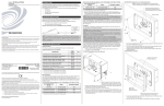
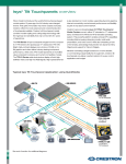
quickstart guide TST-600 1 5.7” Wireless Touch Screen 2 Battery Switch Configure the Touch Screen The TST-600 from Crestron® ships with the battery switch (on the rear) in the OFF (downward) position. The OFF position is used for shipping and long term storage only. Use the included T-pin to turn the switch ON (slide it upward) and place the TST-600 on the included docking station/charger for a minimum of four hours before using. The main menu is the starting point for configuring the TST-600. If no project is loaded, touch the screen to access the main menu. If a project is running, the main menu can be accessed by using the following procedure: To charge the internal battery, the TST-600 must be placed on the TST-600-DS Docking Station, which must be connected to a powered TST-600-IMCW Interface Module (included). 2. When the display turns black, then displays a “3”, release the trigger key. 1. Press and hold the left trigger key on the top of the touch screen until the unit resets (approximately 5 seconds). 3. When “Loading Crestron Applications” appears on the display, touch the screen. 4. Release the touch screen when “Preparing to enter setup” appears. The main menu can also be accessed by pressing HOME, MEDIA, and, on the left of the touch screen display, in sequence twice (press HOME, MEDIA, , , HOME, MEDIA, , ) within a 5 second period. Up NOTE: From any of the setup menus, touch to go back to the previous menu. For details on configuring the TST-600, refer to the TST-600 Configuration Guide (Doc. 7383) at www.crestron.com/manuals. 3 Basic Wireless Setup Before a TST-600 can be used with a Crestron control system, it must first be acquired by a CEN(I)-ERFGW-POE Extended Range RF Wireless Gateway (sold separately). NOTE: Select an RF channel between 12 and 23 for maximum range. Channels 11, 24-26 will result in less range but are available if RF interference requires moving the RF channel. To acquire a TST-600: 1. Use a stylus or other thin tipped object to press ACQUIRE on the CEN(I)-ERFGW-POE gateway to enter Acquire mode. The accompanying LED illuminates, indicating the unit is ready to link with the touch screen. 2. From the main menu on the TST-600, touch RF Setup to display the RF Setup screen. Then place the TST-600 in Acquire mode by touching Acquire on the RF Setup screen. The screen displays an “Acquire in progress” message and the TST-600 is automatically acquired by the gateway within 2 minutes. 3. When the process is complete, the screen displays an “Acquire OK” message. Press ACQUIRE on the gateway to exit Acquire mode. The LED turns off. RF Setup Screen RF Setup (Acquire in Progress) Screen IEEE 802.15.4 Channel Selection (2400 MHz PHY) Channel 1 (802.11b/g) Channel 11 2410 2400 MHz 12 2415 Channel 6 (802.11b/g) 13 2420 2412 MHz 14 2425 15 2430 22 MHz 17 18 16 2435 2440 2445 Channel 11 (802.11b/g) 2 MHz 19 2450 20 2455 2437 MHz 21 2460 22 2465 2462 MHz 23 2470 24 2475 25 26 2480 2483.5 MHz RF (802.15.4) Wi-Fi (802.11b/g) RF Setup (Acquire OK) Screen For details, refer to “Appendix A: The RF Spectrum” and “Appendix B: Optimum RF Reception Guidelines” in the TST-600 Configuration Guide (Doc. 7383). 1 For regulatory compliance information, refer to Doc. 7382. www.crestron.com QUICKSTART DOC. 7381E (2034457, Sheet 1 of 2) 09.14 Specifications subject to change without notice. 888.273.7876 201.767.3400 TST-600 NOTE: The RF ID of the unit must match the RF ID specified in the SIMPL Windows program. quickstart guide TST-600 4 5.7” Wireless Touch Screen Networking Setup From the main menu, touch Networking Setup to display the Networking Setup - Choose WiFi or LAN menu. Out of the box, LAN access is turned on. To switch to Wi-Fi® access, touch On under WiFi Access, then touch Reboot Required to Apply Networking Changes to reboot the TST-600. The left side of the Connect to a WiFi Access Point: 1-2-3 menu displays a list of available access points. Touch the name of the desired access point. If a static IP address is preferred, from the WiFi Setup menu, touch Set Static IP Address Settings to display the WiFi Setup - Static IPs menu. To stay with DHCP, skip to the bottom of this column to connect to a WiFi access point. The name and security type for the selected access point are displayed on the right side of the screen. The WiFi Setup - Static IPs menu is used to edit Static IP address, Static Subnet Mask, Static Default Router, Preferred DNS and Alternate Preferred DNS settings. Touch each to display a keypad for entering the new setting. Enter the password for the access point and touch Save. To set up Wi-Fi, proceed to the next column. The TST-600 ships with DHCP enabled by default. To enter static IP settings, touch LAN Setup to display the Ethernet Setup menu. From the Ethernet Setup menu, touch Set Static IP Address Settings to display the Ethernet Setup - Static IPs menu. Touch Setup menu. Touch the area below the word Password to display a keyboard for password entry. The password will appear below the WAP Name and Security entries on the right side of the screen. Touch Step 3 - Make this my Access Point. to return to the WiFi From the WiFi Setup menu, touch Select a WiFi Access Point to display the Connect to a WiFi Access Point: 1-2-3 menu. Touch Reboot Required to Apply IP Changes to save the new settings and reboot the TST-600. Touch Reboot Required to Apply IP Changes to save the new settings and reboot the TST-600. For regulatory compliance information, refer to Doc. 7382. www.crestron.com QUICKSTART DOC. 7381E (2034457, Sheet 1 of 2) 09.14 Specifications subject to change without notice. 888.273.7876 201.767.3400 TST-600 The Ethernet Setup - Static IPs menu is used to edit Static IP address, Static Subnet Mask, Static Default Router, Preferred DNS and Alternate Preferred DNS settings. Touch each to display a keypad for entering the new setting. 2 To enter Wi-Fi settings, from the Networking Setup - Choose WiFi or LAN menu, touch WiFi Setup to display the WiFi Setup menu. quickstart guide TST-600 5 5.7” Wireless Touch Screen Establish Communication 6 Hardware Hookup Use Crestron Toolbox™ for communicating with the TST-600; refer to the Crestron Toolbox help file for details. There are three methods of communication: TCP/IP, Indirect (using Wi-Fi) and USB. When the TST-600 is set for Wi-Fi, after it has been successfully acquired by a CEN(I)-ERFGW-POE gateway (refer to section ➌), the TST-600 does not require any physical connections for wireless operation. When using a wired LAN, the TST-600 must be placed on the TST-600-DS Docking Station, which must be connected to a powered TST-600-IMCW Interface Module (both included) or it must be placed in the TST-600-DSW Wall Mount Docking Station (sold separately). It must also be in LAN mode. Refer to section ➍ “Networking Setup” on page 2 for details. When set for wired LAN , the TST-600 must be placed on the TST-600-DS Docking Station, which must be connected to a powered TST-600-IMCW Interface Module (both included) or it must be placed in the TST-600-DSW Wall Mount Docking Station (sold separately). Ethernet Communication (LAN Communication is Enabled) For details, refer to the TST-600-DS Installation Guide (Doc. 7433) and the TST-600-IMCW Installation Guide (Doc. 7385) at www.crestron.com/manuals. TST-600-IMCW (Front and Rear Views) TST-600 N TO PANEL: Connect to TST-600-DS Docking Station via 10-Pin RJ-50 Cable (Provided with Docking Station) LA PC Running Crestron Toolbox TST-600 connects to PC via Ethernet: 1. Use the Device Discovery Tool (click the icon) in Crestron Toolbox to detect all Ethernet devices on the network and their IP configuration. The tool is available in Toolbox version 1.15.143 or later. 2. Click on the TST-600 to display information about the device. LAN: 10BASE-T / 100BASE-TX Ethernet to LAN PWR*: From DC Power Pack Wi-Fi Communication (Wi-Fi Communication is Enabled) 24 G: 24 VDC Power Input * A ferrule dust cap is provided to cover the dc power jack when not in use. TST-600 CEN-WAP-ABG 7 N LA Dimensions TST-600 (Front and Side Views) 8.08 in (206 mm) NETWORK PoE LAN PC Running Crestron Toolbox Using Wi-Fi, the TST-600 can communicate directly with the PC via the network. 5.60 in (143 mm) 1.59 in (41 mm) USB Communication 4.51 in (115 mm) 1.07 in (28 mm) TST-600 3.38 in (86 mm) PC Running Crestron Toolbox 5.10 in (130 mm) The USB port on the TST-600 connects to USB port on the PC via the included Type A to Type B USB cable: 3 1. Select Tools > System Info. 2. Click the 3. For Connection Type, select USB. When multiple USB devices are connected, identify the TST-600 by entering “TST-600” in the Model text box, the unit’s serial number in the Serial text box or the unit’s hostname (if known) in the Hostname text box. 4. Click OK. Communications are confirmed when the device information is displayed. icon. For regulatory compliance information, refer to Doc. 7382. www.crestron.com QUICKSTART DOC. 7381E (2034457, Sheet 2 of 2) 09.14 Specifications subject to change without notice. 888.273.7876 201.767.3400 TST-600 USB quickstart guide TST-600 8 5.7” Wireless Touch Screen Specifications 4 Touch Screen Display Connectors Display Type: TFT active matrix color LCD Size: 5.7 inch (145 mm) diagonal Aspect Ratio: 4:3 VGA Resolution: 640 x 480 pixels Brightness: 350 nits (cd/m2) Contrast: 800:1 Color Depth: 18-bit, 262k colors Illumination: Edgelit LED Viewing Angle: ±80° horizontal, ±70° vertical Touch Screen: Projected capacitive Docking Connector: (1) Multi-pin connector Mates with the docking port on the docking station USB: (1) Mini-B USB console port, for installer use only Mini-B to A USB cable included Battery Internal Battery: Li-ion, 3.7 Volt, 3600 mAh, model TST-600-BTP Usage per Charge: 3.5 hours continuous, 100 hours under normal use (10% active duty cycle with standby/power down enabled) Charging Time: 2.5 hours with touch screen in standby, 3.5 to 5 hours during use Buttons, Switches & Indicators Power Requirements Sleep: (1) Top-mounted push button (left); programmable, normally initiates “Sleep” mode when docked, turns power on/off when undocked; also resets the unit if held for 5 seconds Brightness: (1) Top-mounted push button (right); programmable, normally sets display brightness level Hard Keys: (8) Optional push buttons, programmable, engravable backlit text (black models only) Up/Down: (2) Optional backlit translucent “up/down” push buttons, programmable, engravable backlit text on bezel (black models only) Thumbpad: (5) Optional backlit translucent push buttons for 4-way directional navigation and “enter”, programmable Battery Switch: (1) Rear panel recessed slide switch, shuts off battery for long-term storage Battery LED: (1) Green LED, indicates battery condition and charging status when docked Power Pack: 0.75 amps @ 24 Vdc 100-240 Vac, 50/60 Hz power pack included Cresnet® Power Usage: 18 watts (0.75 amps @ 24 Vdc), includes TST-600-IMCW module Note: May be powered by power pack or Cresnet network power, not both. Does not support Cresnet data communication, only power. All power connections are made via the TST-600-IMCW interface module. Memory Environmental LPDDR2 RAM: 1 GB Flash: 4 GB Maximum Project Size: 512 MB Temperature: 32° to 112° F (0° to 45° C), 50° to 104° F (10° to 40° C) while charging Humidity: 10% to 90% RH (non-condensing) Heat Dissipation: 40 Btu/h Enclosure Graphics Engine Construction: Plastic, non-slip grips/feet, integral docking station port Front Bezels: Plastic, button and no-button bezels included, button bezel includes white translucent illuminated Up/Down and Thumbpad buttons and 8 hardkey buttons with illuminated dividers and default backlit text engraving, optional custom backlit text engraving sold separately (black models only) Support Smart Graphics™ 1 Wireless Communication – Extended Range RF2 Dimensions RF Transceiver: 2-way RF, 2.4 GHz ISM Channels 11-26 (2400 to 2483.5 MHz), IEEE 802.15.4 compliant Transmitting Power: 75 mW (Ch.11), 100 mW (Ch.12-23), 15 mW (Ch.24), 3.5 mW (Ch.25), 1 mW (Ch.26) @ High Setting; 1 mW (Ch.11-25), 0.5 mW (Ch.26) @ Low Setting Range (typical): 100 to 200 feet (30 to 61 meters) maximum indoor, 1000 feet (305 meters) outdoor, subject to site-specific conditions Gateway: Requires a CEN-ERFGW-POE Extended Range RF Gateway (sold separately) Height: 5.10 in (130 mm) Width: 8.08 in (206 mm) Depth: 1.59 in (41 mm) Wireless Communication – Wi-Fi2 Weight Transceiver: IEEE 802.11a/b/g Wi-Fi (5.8 or 2.4 GHz 2-way RF), static IP or dynamic IP via DHCP, 64 and 128-bit WEP encryption Range: Up to 50 feet (15 meters), subject to site-specific conditions Gateway: Requires a CEN-WAP-ABG or similar 802.11a/b/g wireless access point and Ethernet-enabled Crestron control system 23 oz (636 g) Ethernet: (Via docking station) 10/100 Mbps, auto-switching, auto-negotiating, auto-discovery, full/half duplex, DHCP USB: USB client for console NOTES 1. 2. 3. 4. Video Supports Smart Graphics only. Not compatible with “traditional” UI projects. ER (Extended Range) RF wireless communication supports basic wireless touch screen functionality and is required for all wireless applications. For advanced functionality including streaming video, intercom and dynamic graphics, Wi-Fi wireless communication is also required (dual-mode). Advanced functionality can also be enabled while docked through a wired Ethernet LAN connection. Streaming video, intercom and dynamic graphics capabilities require dual-mode wireless or a wired Ethernet connection. Refer to TST-600-IMCW interface module specifications for additional connectors. 2 Streaming Formats: H.264 (MPEG-4 part 10 AVC), MJPEG The specific patents that cover Crestron products are listed at patents.crestron.com. Audio ® Features: Built-in microphone and speakers, Rava SIP Intercom Audio Feedback Formats: MP3 Crestron, the Crestron logo, Cresnet, Crestron Toolbox, Rava, and Smart Graphics are either trademarks or registered trademarks of Crestron Electronics, Inc. in the United States and/or other countries. Wi-Fi is either a trademark or registered trademark of Wi-Fi Alliance in the United States and/or other countries. Other trademarks, registered trademarks, and trade names may be used in this document to refer to either the entities claiming the marks and names or their products. Crestron disclaims proprietary interest in the marks and names of others. Crestron is not responsible for errors in typography or photography. 3 This document was written by the Technical Publications department at Crestron. ©2014 Crestron Electronics, Inc. 4 For regulatory compliance information, refer to Doc. 7382. www.crestron.com QUICKSTART DOC. 7381E (2034457, Sheet 2 of 2) 09.14 Specifications subject to change without notice. 888.273.7876 201.767.3400 TST-600 Wired Communication Note: Combined height of the TST-600 touch screen docked on the TST-600-DS docking station is 3.30 in (84 mm).