1
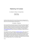
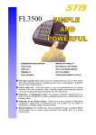
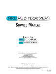
Fingerlock
Technical description
FL-SPDe-602-JB
FL3500
Technical description
Table
1. Introduction
2. Concept
3. Integrated access control system
4. Hardware
4.1. Design
4.2. Connections
4.3. Protection
4.4. Sensor
4.5. Biometric module
5. Software
5.1. Fingerprint management
5.2. Security level
5.3. Master code
6. Features
6.1. Installation
6.2. Principles
6.3. Managers
6.4. Users
6.5. Timelock
6.6. Time Delay
6.7. Dual opening
6.8. Two Locks/ Motorized Lock
6.9. Alarm
6.10. Remote Activation
6.11. Audit trail
7. LED codes
8. Troubleshooting
8.1. Dry fingers
8.2. Finger positioning
9. Glossary
10. Installation process
D:\FL3500\FL-SPDE-602-JB.DOC
Crée le 17.06.02
Par: JMB
Contrôlé le:
Par
Modifié le 01.07.02
Par:
1
2
2
2
3
3
4
5
6
6
6
6
7
7
8
8
8
8
8
9
9
9
9
10
10
10
11
11
11
11
12
14
1/ 14
JMB/ 05.09.02
Technical description
FL3500
1. Introduction
The FL3500 lock family is based on the latest fingerprint technologies to provide you with
a full range of solutions, from a simple and convenient access control system to a sophisticated locking device, integrated in your security concept.
2. Concept
Customers' needs for specific solutions to specific problems have driven STB to design a
security system that will provide answers in several cases where standard mechanical or
electronic locks are not able to do the job.
The recent evolution in fingerprint recognition technology has made it possible to integrate
it in stand-alone applications.
The relatively high cost of the technology does not allow implementing it in mass production, but it offers a powerful option for high security or very precise applications. Its design
takes into account the requirements of the most demanding customers from the banking
and commercial fields.
Very high security level: Unlike any lock, FL3500 gives the user no other option
than being physically present to operate the lock. Fake or dead fingers or fingerprint
pictures cannot cheat its sensor.
Proven audit trail: Audit trails based on keys or combinations are not definite evidence of the user’s presence. Only a biometric system proves that the recorded event
was actually performed by the person the user claims to be.
Verification or Identification mode: The powerful recognition software gives the option to use the FL3500 lock in either verification (one-to-one) or identification (one-tomany) mode.
Integration to an existing system: Thanks to its various possible configurations,
the FL3500 lock can easily be integrated in an already installed security concept.
Remote features: The FL3500 lock can be connected through a standard RS232
communication port to retrieve status information and enable users for a limited period of time.
In addition to these unique features, the FL3500 lock also brings answers to several issues that are commonly related to the use of biometric access control systems.
a. The database of all recorded fingerprints is located inside the security container.
Unlike many other systems, the FL3500 lock design guarantees full protection of the
database. Thanks to a sophisticated design of the communication ports, the distance between the sensor and database has been increased to 1500 mm.
b. The lock works in stand-alone mode, in order to reach several application fields that
were not open to biometrics due to the need for a network.
3. Integrated access control system
The FL3500 lock can be considered as an Integrated Access Control System. Several
hardware and software options make it possible to include it into an existing "network" or
to integrate it in a new global security concept.
D:\FL3500\FL-SPDE-602-JB.DOC
2 / 14
JMB/ 05.09.02
FL3500
Technical description
HID proximity card or Dallas Tag installations can be locally strengthened through the integration of a FL3500 lock in verification mode.
a)
Dallas Tag: As the tag is not used as a security system in itself, but as a
means to address the fingerprint in the database, any Dallas
Tag can be enrolled that is already used for door opening, a
coffee machine or any other application.
b) HID Proxy Card: As with the Dallas, any compatible HID card can be used.
This
includes
Proxcard
II,
Prox
key.
It is obviously also possible to choose its own internal code
when programming the cards or even, for large volume customers, get its own "customized" company code.
c)
PIN N° / Combination: The keypad combination is limited to 6 digits, similar
to most electronic, door or safe locks. However, its use does not
require the same level of precaution as with a standard lock, as
it is only valid in conjunction with one fingerprint.
d) Remote host computer connection: Through its versatile communication
language, the FL3500 lock can be serially connected to a remote computer together with other components of the security
system. Real time supervising of the lock operation is also possible.
e)
Door contact: Existing door switches, part of the security loop, can be connected to the lock and checked from the remote host computer
f)
Camera activation: Waking up the FL3500 lock through the keypad or the
Dallas Tag can send a signal to an external device such as a
CCD camera, to be in position to identify the lock user and if
necessary activate his fingerprint for a limited period of time.
4. Hardware
4.1.
Design
Additional input
Interface
board
Database
Lock housing
Lock Board
Fingerprint Sensor
External housing
Picture: 6
D:\FL3500\FL-SPDE-602-JB.DOC
Solenoid
Basic principle sketch
3 / 14
JMB/ 05.09.02
FL3500
Technical description
The FL3500 lock basically consists of the following components:
Outside the protected area:
a)
a fingerprint sensor able to take a digital picture of the fingerprint, and to
code and transmit it to the internal database/calculator
b) an additional input depending on the lock model
− Wake-up button
− HID proximity card reader
− Dallas Tag reader
All these systems have to be operated
before placing the finger onto the sensor
− 12-button keypad
c)
an interface board to ensure data transmission between inputs a) and b)
and the database/lock board
Inside the protected area:
a) A database/calculator board that stores the fingerprint characteristics and
performs the matching
b) A lock board that performs user recognition and provides all security features
c) A solenoid that blocks and releases the lock mechanism
4.2.
Connections
The FL3500 lock has multiple connection capabilities, either necessary or
optional.
¬
PC serial line (RJ45 8/8)
The RS232 line can only be accessed when the door is open. It is
used to set the lock and user parameters through the FL3500 PC
D:\FL3500\FL-SPDE-602-JB.DOC
4 / 14
JMB/ 05.09.02
Technical description
FL3500
software. It is also used to download audit trails. An authorized manager’s fingerprint is required to use the software.
-
Restricted remote line (RJ45 8/8)
This optional line can be used by the lock to inform a remote computer of its status, and can send audit information in real time. Even if
this line is bi-directional, the only information that can be accepted by
the lock is a temporary enabling of an already stored fingerprint, provided that it has been declared as such with the "Remote activation"
feature. The pin out of this line is obviously different from ¬, even if
the same connector is used for both.
This connection cannot be used when the lock is battery powered.
®
Wake-up Signal
Originally designed to wake-up a camera when the lock is activated,
this signal can be used to operate any external device through a simple relay. It uses a specific cable through the ® connector.
¯
°
±
Power supply (jack plug)
Door contact
A door switch can be connected to the FL3500 lock using the power
supply line. A special cable is provided by STB.
Input from external housing
Consisting of two 10-wire lines (RJ45 connector), this connection is
used to enter information from the sensor, optionally from the keypad,
Dallas Tag or HID Reader. It also sends responses from the Lock
board to the LED.
4.3.
Protection
a) Hardware
Fraud
There is no direct connection to the fingerprint database
from the outside. Fingerprints cannot be retrieved from
the database.
ESD
The lock is designed to comply with the EMC principle.
All lock parts are connected to ground. Fuses protect
sensible components.
Tearing off
A protected switch disables the lock in case of pulling
away from its mounting surface.
b) Software
FL3500
PC plugging is only possible when the door is open.
Software access is limited to managers’ recognized fingerprints.
Access to maintenance menu requires positive manager
identification and the installer code.
D:\FL3500\FL-SPDE-602-JB.DOC
5 / 14
JMB/ 05.09.02
Technical description
4.4.
Sensor
Technical Data:
Sensor Technology:
Sensor Resolution:
Sensor Area:
Number of Pixels:
4.5.
FL3500
Capacitive C-MOS Sensor, 256 gray tones
513 dpi
11 mm x 14 mm
224 x 288
Biometric module
Technical Data
Computing Time:
1 second for encoding + matching (Verification)
+5 ms for further matching
False Rejection < 5 x 10 –3 (real using scenario
and cooperative user)
False Acceptance <10 -6 (real using scenario
and cooperative user)
Rate (FRR):
Rate (FAR):
5. Software
5.1.
Fingerprint management
Unlike several other biometric systems, the FL3500 lock series do not give
the managers or users any access to the fingerprints themselves. In other
words, it is impossible
− to display the fingerprint on the PC.
− to download the fingerprint template from the lock to any other support.
− to network the locks and transfer the fingerprint to another FL3500
lock.
These technical choices have been made for both security and privacy reasons.
Keypad
1 2 3
4 5 6
7 8 9
*0 #
LED
or
Proximity card
or
Lock Board
Dallas Tag
Solenoid
Yes
No
->Id N°
Known ?
Fingerprint
sensor
Database /
calculator
Outside the security container
D:\FL3500\FL-SPDE-602-JB.DOC
6 / 14
Inside the security container
JMB/ 05.09.02
Technical description
FL3500
The captured fingerprint is transmitted from the sensor to the database/calculator. In verification mode, it is associated with a PIN number,
which goes directly to the lock board. This latter receives the answer as to
whether or not the fingerprint is stored in the database, and checks whether
its owner is who he claims to be. It then also verifies if this user has the
right to operate the lock at this time and under the current conditions.
5.2.
Security level
The security level of the lock can be selected from 3 possible levels:
è Standard
è Medium
è High
The levels can be understood as the required score of the templates similarity. In other words, the standard level will return a positive answer with a
70% similarity, whereas 80% is required at the medium level and 90% at
the high level (these percentages are used only for the sake of explanation;
the actual rating system is more sophisticated).
The consequence of a higher level is obviously a reduction in the False Acceptance Rate (See §2.6), i.e. fewer people are given access by mistake
through a similarity with authorized fingerprints. But it also increases the
False Rejection Rate, meaning that more authorized people will not be recognized because of bad finger positioning, or dirt or scars on their fingertip.
The other parameters of the lock are not affected.
5.3.
Master (or Installer) code
FL3500 lock parameters are programmed through the FL3500 PC software.
These parameters are divided into two groups
a) Parameters that are set by the installer and can only be changed by
them
b) Parameters that can be changed at any time by an authorized manager
The purpose of this feature is to avoid local or corporate security rules being modified. It mainly refers to hardware features, manager’s and user’s
number, timelock and time-delay bypass…
The installer code is supplied by STB with each lock. It can either be
unique, dedicated to an installer or, for large accounts, dedicated to the final customer. This code cannot be read in any way and cannot be
changed.
This code is used to enter the FL3500 lock software at the first installation
and must be re-entered each time the installer wants to modify the lock’s
basic settings.
STB keeps track of each installer code in relationship with the lock serial
number.
D:\FL3500\FL-SPDE-602-JB.DOC
7 / 14
JMB/ 05.09.02
Technical description
FL3500
6. Features
6.1.
Installation
All FL3500 locks are shipped with the same basic software configuration.
Only the installer code is stored by the factory.
This aims to make inventory management much easier for installers and
distributors. Any configuration of FL3500 external housing can be used with
any FL3500 lock housing. This latter is automatically identified by the lock
board. The installer has to specify the other hardware parameters, such as
power supply or RS232 features, as well as software parameters, for example the number of users or wrong try penalties.
6.2.
Principles
The FL3500 configuration is made via a PC serial line. The PC is connected to the inside of the lock housing. No action is possible from the external housing. All day-to-day operations can be performed without a PC; it
is however required to first install the lock, set and modify parameters and
retrieve audit trails. Regular users’ enrollment can be performed in standalone mode; it is however not possible to apply special restrictions, such as
dual custody or remote activation.
6.3.
Managers
The FL3500 lock accepts between 1 and 5 managers. At the end of the first
installation, one manager must obviously be enrolled with an opening finger.
The managers have access to a limited configuration menu that includes:
• Time correction
• Enabling/disabling of stand-alone mode
• Timelock and Time delay settings
•
•
Holiday settings
Managers’ and users’ administration
Audits can also be performed from this menu.
For each manager it is possible:
6.4.
•
•
•
To enroll an alternate opening finger
To give him the right to enroll and delete users in stand-alone mode
To enroll a delete and/or enroll finger
•
•
•
To allot him to a time range (shift)
To restrict his right to dual custody
In dual lock mode, to give him access to one or the other locks
Users
The FL3500 lock can manage up to 50 user fingerprints. This means that it
can store either one fingerprint for 50 users or 2 fingerprints for a maximum
of 25 users.
D:\FL3500\FL-SPDE-602-JB.DOC
8 / 14
JMB/ 05.09.02
FL3500
Technical description
Each user can be individually managed, with specific privileges, allotment
to different groups in dual custody mode or in different shifts for individual
Timelocks.
6.5.
Timelock
The FL3500 Timelock features are organized on four different levels:
• An yearly calendar, including 15 holidays and 2 annual closings
• A standard week with 2 openings/closings per day
• Four different shifts with 2 openings/closings each per day
• Five Timelock exceptions programmable in date and time
The shift programs must obviously be included in the standard week.
6.6.
Time delay
The installer must set the minimal Time delay, according to local or corporate regulations.
Managers can set the delay period from 1 to 99 minutes, and the opening
window from 1 to 19 minutes. In dual custody, one fingerprint can start the
time delay and two are required to open at the end of the delay period.
6.7.
Dual custody
Dual custody can be applied to managers as well as to users. In order to
increase security, users can be allotted to three different groups.
GROUP 2
GROUP 3
GROUP 1
6.8.
•
Users belonging to group 1 can open with any other user
•
Users belonging to group 2 can only open with users of group 1 or 3
•
Users belonging to group 3 can only open with users of group 1 or 2
Dual Lock / motor lock
The FL3500 lock can manage two locks, one master lock incorporating the
lock board and a slave lock.
In dual lock mode, it is necessary to specify which lock each user and
manager can open.
If a motor lock is used, only one lock can be installed.
D:\FL3500\FL-SPDE-602-JB.DOC
9 / 14
JMB/ 05.09.02
Technical description
6.9.
FL3500
Alarm
This feature can be made available with the FL3500 lock in a very simple
way. The output relay originally designed for the 2nd lock can be used as an
alarm connection. It simply requires declaring a dual lock system and
enrolling the user with one finger for Lock A, regular opening, and one
finger for Lock B, the alarm finger. If finger "Lock A" is used, the lock will
open; if finger "Lock B" is used, the lock will not open but an alarm signal
will be sent.
6.10.
Remote activation
A user can be limited by three different "Timelock statuses"
−
General Timelock program
−
Shift 1 to 4
−
Fingerprint not enabled
This last status is mainly applied to users accessing the lock for a small
number of times without accurate schedules, such as cash carriers at
ATMs. This option allows requesting fingerprint activation from the remote
computer location for a limited period of time. The enabling signal is sent
through the serial line. The fingerprint can be used for a determined number of minutes and is then automatically disabled.
Use of this feature obviously requires a remote RS232 connection.
6.11.
Audit trail
The FL3500 lock stores up to 300 events in loop. This means that when the
memory is full, the oldest events are replaced by the newer ones.
The following events are identified by a code number
- Successful lock opening
- Opening attempted during general "Timelock period"
- Opening attempted out of shift time
- Non identified fingerprint
- Identified fingerprint starting delay period
- 1st fingerprint of dual opening
- Remote enabling of a fingerprint
- Stand-alone enrollment
- Stand-alone deletion
- Plugging of the programming computer
- Configuration modification
- Successful entering of installer code
The stored/transmitted data includes:
- Event number
- Date and time
- Event code and description
- User serial number
The data can be downloaded onto the PC or transmitted in real time to the
remote host computer.
D:\FL3500\FL-SPDE-602-JB.DOC
10 / 14
JMB/ 05.09.02
Technical description
FL3500
7. LED codes
The lock status and events are transmitted to the user through a 3-colour
LED. The following codes are used:
Status / Event
Green Orange Red
Note
Lock asleep
Waiting for a TAG / PIN
Waiting for a finger
Wrong TAG or PIN
Wrong fingerprint
Waiting for new TAG or PIN
Blinking
Waiting for new finger
Blinking
Waiting for TAG or PIN to be deleted
Alternately
Waiting for finger to be deleted
Alternately
Lock open
Fast blinking during opening
Low battery
Fast blinking during opening
System default
Fast blinking during opening
Opening attempt during Timelock period
G: 0.5s O: 0.5s R: 1s
Opening attempt in dual mode with
non authorized user
G: 0.5s O: 0.5s R: 1s
Time delay
Alternately, every 10 seconds
Opening window
2 blinks every 10 seconds
Penalty period
Alternately, every 10 seconds
Desynchronized clock
Blinking during opening
8. Troubleshooting
8.1.
Dry finger
About 5-10% of the population have fingers that are difficult to enroll and
recognize. Dry finger skin may prevent easy identification. Moistening one's
finger with the breath should solve most problems.
8.2.
Bad finger positioning
Finger positioning is crucial to get a good template quality at the enrollment
and a reliable recognition afterwards. Always place the finger in a horizontal position and centered on the sensor. Pressing one's finger on the sensor
does not help.
D:\FL3500\FL-SPDE-602-JB.DOC
11 / 14
JMB/ 05.09.02
Technical description
9. Glossary
Word
Algorithm
Alternate Fingers
Attempt
Biometrics
Biometric Data
Biometric System
Enroller
Enrollment
Enrollment Quality
Enrollment Time
Equal Error Rate
Failure to Acquire
Failure to Acquire Rate
False Acceptance
False Acceptance Rate
(FAR)
False Finger / Fake Finger
Detection
False Finger Level /
Threshold
False Rejection
False Rejection Rate
(FRR)
Host Computer
D:\FL3500\FL-SPDE-602-JB.DOC
FL3500
Explanation
Mathematical process of comparing the presented biometric
property with the template, which has been stored before, or
serves to calculate the template.
Enrollment of other fingers over and above the first finger, to
permit verification even when the primary finger is injured.
Presentation of biometric properties on a biometric unit with
the aim of verification or identification. Biometric systems may
allow more than one attempt.
The use of measurable personal properties in order to identify
or verify a person using automatic means.
Data extracted from the presented biometric properties, which
serve to calculate the template.
Automatic system to
o
capture biometric data
o
compare with a stored template
o
decide on degree of similarity
o
output the result of the verification
Person with the authority to enroll other users.
Enrollment of a person onto a biometric system. This includes
automatic reading of the biometric properties (e.g. a fingerprint), creation of a biometric template with biometric characteristics used for later comparison.
Measure of quality of the enrollment of a person, and indicator of whether the enrollment should be repeated.
Time required for enrollment of a new user, including memorizing the biometric template.
Adjustment of a biometric system to make False Acceptance
and False Reject the same.
Enrollment reject of a person by the biometric system.
Ratio of persons for which registration was refused versus
total number of enrolled persons (in %).
Recognizing a not enrolled person as enrolled (and hence
authorized)
Ratio of wrongly recognized persons versus total of checked
persons (measured in %).
In fingerprint systems the detection of a non-living finger (i.e.
an attempt to cheat the system).
In fingerprint systems, the security level that allows the recognition of a false finger.
Refusal to recognize an enrolled (and hence authorized) person.
Ratio of wrongly, not recognized persons versus total of
checked persons (measured in %).
Computer, which performs the central tasks in a biometric
system with more than one terminal, including storage of
templates.
12 / 14
JMB/ 05.09.02
Technical description
ID Number, PIN
Identification
Local Database
Magnetic Stripe Card
Optics System
Security Threshold
Template
Transaction
Transaction Log
Verification
Verification Threshold
Verification Time
D:\FL3500\FL-SPDE-602-JB.DOC
FL3500
In biometric systems, a number (generally not kept secret)
used to call up the biometric template from the database.
Identifying a person based on biometric properties without
knowing the (pretended) identity beforehand (one-to-many).
Database of biometric templates residing in the biometric unit.
Use of a magnetically readable card for PIN input. Simplifies
and speeds up verification processes.
Optical systems with electronic cameras are used to read
certain biometric properties.
Adjustable threshold for the comparison of biometric properties of a person. Influences False Acceptance as well as
False Rejects.
Digitally encrypted properties of biometric data of a person,
which are used as a reference during verification.
Activity or event in a biometric unit that creates a system
message.
List of all transactions in a biometric unit.
Checking the identity of a person using the biometric template
previously stored. Consists of entry of the claimed identity
and presentation of the biometric property (one-to-one).
See security threshold.
Time between presentation of a biometric property and output
of the verification result.
13 / 14
JMB/ 05.09.02
FL3500
10. Installation
Yes
1
Lock
configuration
Security
level
External RS232
configuration
External
power
supply ?
No
No External
RS232
Yes
2
Max. N° of
users
Stand-alone
enrolment ?
Dual Lock ?
No
3
4
N° of wrong
tries before
penalty
Configuration
summary
D:\FL3500\FL-SPDE-602-JB.DOC
First penalty
period
First manager
enrollment
14 / 14
Max. N° of
managers
Second penalty
period
Installer code
entering
JMB/ 05.09.02
Lock 1
holding time
2
Lock 2
holding time
3
Lock 1
holding time
Timelock
enabled ?
Actual time
confirmation
Time delay
enabled ?
4