1
Sun StorEdge™ T3 and T3+ Array
Site Preparation Guide
Sun Microsystems, Inc.
901 San Antonio Road
Palo Alto, CA 94303-4900 U.S.A.
650-960-1300
Part No.816-0778-10
August 2001, Revision A
Send comments about this document to: [email protected]
Copyright 2001 Sun Microsystems, Inc., 901 San Antonio Road, Palo Alto, CA 94303-4900 U.S.A. All rights reserved.
This product or document is distributed under licenses restricting its use, copying, distribution, and decompilation. No part of this product or
document may be reproduced in any form by any means without prior written authorization of Sun and its licensors, if any. Third-party
software, including font technology, is copyrighted and licensed from Sun suppliers.
Parts of the product may be derived from Berkeley BSD systems, licensed from the University of California. UNIX is a registered trademark in
the U.S. and other countries, exclusively licensed through X/Open Company, Ltd.
Sun, Sun Microsystems, the Sun logo, AnswerBook2, docs.sun.com, Sun StorEdge, SunDocs, SunService, StorTools, Sun StorEdge Component
Manager and Solaris are trademarks, registered trademarks, or service marks of Sun Microsystems, Inc. in the U.S. and other countries. All
SPARC trademarks are used under license and are trademarks or registered trademarks of SPARC International, Inc. in the U.S. and other
countries. Products bearing SPARC trademarks are based upon an architecture developed by Sun Microsystems, Inc.
The OPEN LOOK and Sun™ Graphical User Interface was developed by Sun Microsystems, Inc. for its users and licensees. Sun acknowledges
the pioneering efforts of Xerox in researching and developing the concept of visual or graphical user interfaces for the computer industry. Sun
holds a non-exclusive license from Xerox to the Xerox Graphical User Interface, which license also covers Sun’s licensees who implement OPEN
LOOK GUIs and otherwise comply with Sun’s written license agreements.
Federal Acquisitions: Commercial Software—Government Users Subject to Standard License Terms and Conditions.
DOCUMENTATION IS PROVIDED “AS IS” AND ALL EXPRESS OR IMPLIED CONDITIONS, REPRESENTATIONS AND WARRANTIES,
INCLUDING ANY IMPLIED WARRANTY OF MERCHANTABILITY, FITNESS FOR A PARTICULAR PURPOSE OR NON-INFRINGEMENT,
ARE DISCLAIMED, EXCEPT TO THE EXTENT THAT SUCH DISCLAIMERS ARE HELD TO BE LEGALLY INVALID.
Copyright 2001 Sun Microsystems, Inc., 901 San Antonio Road, Palo Alto, CA 94303-4900 Etats-Unis. Tous droits réservés.
Ce produit ou document est distribué avec des licences qui en restreignent l’utilisation, la copie, la distribution, et la décompilation. Aucune
partie de ce produit ou document ne peut être reproduite sous aucune forme, par quelque moyen que ce soit, sans l’autorisation préalable et
écrite de Sun et de ses bailleurs de licence, s’il y en a. Le logiciel détenu par des tiers, et qui comprend la technologie relative aux polices de
caractères, est protégé par un copyright et licencié par des fournisseurs de Sun.
Des parties de ce produit pourront être dérivées des systèmes Berkeley BSD licenciés par l’Université de Californie. UNIX est une marque
déposée aux Etats-Unis et dans d’autres pays et licenciée exclusivement par X/Open Company, Ltd.
Sun, Sun Microsystems, le logo Sun, AnswerBook2, docs.sun.com, Sun StorEdge, SunDocs, SunService, StorTools, Sun StorEdge Component
Manager, et Solaris sont des marques de fabrique ou des marques déposées, ou marques de service, de Sun Microsystems, Inc. aux Etats-Unis et
dans d’autres pays. Toutes les marques SPARC sont utilisées sous licence et sont des marques de fabrique ou des marques déposées de SPARC
International, Inc. aux Etats-Unis et dans d’autres pays. Les produits portant les marques SPARC sont basés sur une architecture développée par
Sun Microsystems, Inc.
L’interface d’utilisation graphique OPEN LOOK et Sun™ a été développée par Sun Microsystems, Inc. pour ses utilisateurs et licenciés. Sun
reconnaît les efforts de pionniers de Xerox pour la recherche et le développement du concept des interfaces d’utilisation visuelle ou graphique
pour l’industrie de l’informatique. Sun détient une licence non exclusive de Xerox sur l’interface d’utilisation graphique Xerox, cette licence
couvrant également les licenciés de Sun qui mettent en place l’interface d’utilisation graphique OPEN LOOK et qui en outre se conforment aux
licences écrites de Sun.
LA DOCUMENTATION EST FOURNIE “EN L’ETAT” ET TOUTES AUTRES CONDITIONS, DECLARATIONS ET GARANTIES EXPRESSES
OU TACITES SONT FORMELLEMENT EXCLUES, DANS LA MESURE AUTORISEE PAR LA LOI APPLICABLE, Y COMPRIS NOTAMMENT
TOUTE GARANTIE IMPLICITE RELATIVE A LA QUALITE MARCHANDE, A L’APTITUDE A UNE UTILISATION PARTICULIERE OU A
L’ABSENCE DE CONTREFAÇON.
Please
Recycle
Contents
Preface
1.
2.
ix
Site Planning Overview
1.1
Product Description
1.2
Customer Obligations
Local Facility Safety
1-2
1-3
2-1
2.1
Handling Precautions
2.2
Safety Precautions
2.2.1
3.
1-1
2-2
2-2
Power Safety
2-2
2.3
Placement of a Sun Product
2.4
Laser Compliance Notice
Facility Requirements
3.1
3.2
2-3
2-3
3-1
Environmental Specifications
3-2
3.1.1
Electromagnetic Compatibility (EMC)
3.1.2
Secure Installation Requirements
3-2
3.1.2.1
Placement of Rackmounted Systems
3.1.2.2
Placement of Individual Tabletop Units
Electrical and Power Specifications
3.2.1
3-2
3-3
3-3
3-3
Sun StorEdge T3 and T3+ Array
Rackmounted Systems 3-3
Contents
iii
3.2.2
3.3
Sun StorEdge T3 and T3+ Array Units
Physical Specifications
3.3.1
3-5
Sun StorEdge T3 and T3+ Array
Rackmounted Systems 3-5
3.3.2
3.3.1.1
Installation Clearances
3.3.1.2
Cooling Clearances
3.3.1.3
Physical Dimensions
3-5
3-6
Sun StorEdge T3 and T3+ Array Units
3.3.2.1
Installation Clearances
3.3.2.2
Cooling Clearances
3.3.2.3
Physical Dimensions
3-6
3-6
5.
Array Rack and Tabletop Installation Requirements
4-1
5.1
Array Rack Placement
5.2
Tabletop Placement
5-3
5.3
Cable Specifications
5-4
5-2
A-1
Cabinet and Rack Hardware
A-2
A.1.1
Physical Dimensions
A-2
A.1.2
Vertical Mounting Space
A-4
A.2
Specifications
A.3
Product Servicing
A.4
SunService Policy on Third-Party Products
A-6
A-7
B. Preinstallation Worksheet
A-8
B-1
B.1
Host System Types
B.2
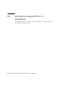
Information Required Prior to Installation
Glossary
3-6
3-6
Unpacking the Array Rack
A. Cabinet and Rack Requirements
iv
3-5
4.
A.1
3-4
B-1
Glossary-1
Sun StorEdge T3 and T3+ Array Site Preparation Guide • August 2001
B-2
5-1
Figures
FIGURE 1-1
Sun StorEdge T3+ Array Enterprise Configuration
1-3
FIGURE 4-1
Sun StorEdge T3 and T3+ Array Rack Packaging
4-2
FIGURE 4-2
Rack Packaging Removal Detail
FIGURE 4-3
Removing the Saddle Bag and Positioning the Ramps
FIGURE A-1
Cabinet and Rack Physical Measurements A-3
FIGURE A-2
Industry Standard Repeating Hole Pattern A-4
FIGURE A-3
Rack Unit Spacing A-5
4-3
4-4
v
vi
Sun StorEdge T3 and T3+ Array Site Preparation Guide • August 2001
Tables
TABLE 3-1
Facility Environmental Specifications 3-2
TABLE 3-2
Power Specifications for the Array Rack (Each Conditioner Source) 3-4
TABLE 3-3
Power Specifications for the Sun StorEdge T3 and T3+ Array (Each Source)
TABLE 3-4
Sun StorEdge T3 and T3+ Array Racks 3-6
TABLE 3-5
Sun StorEdge T3 and T3+ Array Units 3-6
TABLE 4-1
Array Rack Packaging Dimensions
TABLE 4-2
Sun StorEdge T3 and T3+ Array Rack Dimensions 4-5
TABLE 5-1
Cable Specifications 5-4
TABLE A-1
Cabinet and Rack Dimensions A-2
TABLE A-2
Mounting Kit RU Measurement
TABLE A-3
Power Specifications
TABLE A-4
Environmental Specifications A-6
TABLE B-1
Host System Types B-1
3-4
4-2
A-4
A-6
vii
viii Sun StorEdge T3 and T3+ Array Site Preparation Guide • August 2001
Preface
The Sun StorEdge T3 and T3+ Array Site Preparation Guide provides information on
preparing a customer site for installation of a Sun StorEdge™ T3 or T3+ array, or an
array rack system. This guide is intended for Sun™ field sales and technical support
personnel.
Before You Read This Book
Read the Sun StorEdge T3 Installation, Operation, and Service Manual for product
overview information. Read the safety information in the Sun StorEdge T3 and T3+
Array Regulatory and Safety Compliance Manual that is included with the array before
attempting the installation.
How This Book Is Organized
Chapter 1 provides an overview of the preparation and installation requirements for
the array.
Chapter 2 provides safety information for the local facility.
Chapter 3 describes facility requirements for the array.
Chapter 4 shows, in pictorial form, how a rack of Sun StorEdge T3 and T3+ arrays is
packaged, and how to unpack it. It also describes how much clearance is needed to
remove the outer packaging, and how to remove it from the shipping pallet.
ix
Chapter 5 describes installation requirements for installing Sun StorEdge T3 and T3+
arrays in a rack or on a tabletop.
Appendix A contains requirements for operating an array in standard 19-inch
EIA/RETMA cabinets and racks.
Appendix B provides a worksheet for gathering and recording the information
required to successfully install an array.
Glossary provides a list of terms used in this document.
Using UNIX Commands
This document contains some information on basic UNIX® commands and
procedures such as booting the devices. For further information, see one or more of
the following:
x
■
AnswerBook2™ online documentation for the Solaris™ software environment
■
Other software documentation that you received with your system
Sun StorEdge T3 and T3+ Array Site Preparation Guide • August 2001
Typographic Conventions
Typeface
Meaning
Examples
AaBbCc123
The names of commands, files,
and directories; on-screen
computer output
Edit your.login file.
Use ls -a to list all files.
% You have mail.
AaBbCc123
What you type, when
contrasted with on-screen
computer output
% su
Password:
AaBbCc123
Book titles, new words or terms,
words to be emphasized
Read Chapter 6 in the User’s Guide.
These are called class options.
You must be superuser to do this.
Command-line variable; replace
with a real name or value
To delete a file, type rm filename.
Shell Prompts
Shell
Prompt
C shell
machine_name%
C shell superuser
machine_name#
Bourne shell and Korn shell
$
Bourne shell and Korn shell superuser
#
Sun StorEdge T3 and T3+ array
:/:
Preface
xi
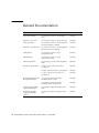
Related Documentation
Application
Title
Part Number
Latest array updates
Sun StorEdge T3 and T3+ Array Release
Notes
816-1983
Installation overview
Sun StorEdge T3 and T3+ Array Start Here
816-0772
Safety procedures
Sun StorEdge T3 and T3+ Array Regulatory
and Safety Compliance Manual
816-0774
Installation and operation
Sun StorEdge T3 and T3+ Array Installation,
Operation, and Service Manual
816-0773
Configuration
Sun StorEdge T3 and T3+ Array
Configuration Guide
816-0777
Administration
Sun StorEdge T3 and T3+ Array
Administrator’s Guide
816-0776
Cabinet installation
Sun StorEdge T3 Array Cabinet Installation
Guide
806-7979
Disk drive specifications
18-Gbyte, 1-inch, 10K rpm Disk Drive
Specifications
806-1493
36 Gbyte, 10K rpm Disk Drive Specifications
806-6383
73 Gbyte, 10K rpm 1.6-Inch Disk Drive
Specifications
806-4800
Sun StorEdge Component Manager
Installation Guide - Solaris
806-6645
Sun StorEdge Component Manager
Installation Guide - Windows NT
806-6646
Using the Sun StorEdge
Component Manager
Sun StorEdge Component Manager User’s
Guide
806-6647
Latest Sun StorEdge
Component Manager
Updates
Sun StorEdge Component Manager Release
Notes
806-6648
Sun StorEdge Component
Manager installation
xii
Sun StorEdge T3 and T3+ Array Site Preparation Guide • August 2001
Accessing Sun Documentation Online
You can find the Sun StorEdge T3 and T3+ array documentation and other select
product documentation for Network Storage Solutions at:
http://www.sun.com/products-n-solutions/hardware/docs/
Network_Storage_Solutions
Sun Welcomes Your Comments
Sun is interested in improving its documentation and welcomes your comments and
suggestions. You can email your comments to Sun at:
[email protected]
Please include the part number (816-0778-10) of your document in the subject line of
your email.
Preface
xiii
xiv
Sun StorEdge T3 and T3+ Array Site Preparation Guide • August 2001
CHAPTER
1
Site Planning Overview
This manual describes facilities and site design, and preparation and installation
requirements for the Sun StorEdge T3 and T3+ array.
To determine the total components and arrays your shipment will include, consult
your local Sun sales representative.
As a guide, typical configurations are included in Appendix A.
This chapter includes the following sections:
■
“Product Description” on page 1-2
■
“Customer Obligations” on page 1-3
1-1
1.1
Product Description
The Sun StorEdge T3 array is a high-performance, modular, scalable storage device
that contains an internal RAID controller and nine disk drives with Fibre Channel
connectivity to the data host. Extensive reliability, availability, and serviceability (RAS)
features include redundant components, notification of failed components, and the
ability to replace components while the unit is online. The Sun StorEdge T3+ array
provides the same features as the Sun StorEdge T3 array, and includes an updated
controller card with direct fiber-optic connectivity and additional memory for data
cache.
The array can be used either as a standalone storage unit or as a building block,
interconnected with other arrays of the same type and configured in various ways to
provide a storage solution optimized to the host application. The array can be placed
on a table top or rackmounted in a server cabinet or expansion cabinet.
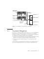
In an enterprise configuration, also called a partner group, two controller units are
paired using interconnect cables for back-end data and administrative connections.
The enterprise configuration provides all the RAS of single controller units, plus
redundant hardware RAID controllers with mirrored caches, and redundant host
channels for continuous data availability for host applications.
In an enterprise configuration, one array is designated the master controller unit,
handling all management services for both arrays. The other array is designated the
alternative master controller unit and supplies controller redundancy, becoming
available as a master controller if the master controller unit fails. For more
information and sample layouts, see Appendix A.
1-2
Sun StorEdge T3 and T3+ Array Site Preparation Guide • August 2001
Alternate master
controller unit
Ethernet
connection
Application host
Interconnect
cables
Host-bus adapters
Master
controller unit
FC-AL connection
Management host
Ethernet
connection
LAN
Ethernet port
FIGURE 1-1
1.2
Sun StorEdge T3+ Array Enterprise Configuration
Customer Obligations
The customer is obliged to inform Sun Microsystems, Inc. of any and all ordinances
and regulations that would affect installation. The customer is responsible for
meeting all government codes and regulations concerning facilities. The customer is
also responsible for compliance with the following requirements:
1. Meet all local, national, and international codes covered in this specification. The
subjects covered include fire and safety, building, and electrical codes.
2. Document and inform Sun Microsystems, Inc. of any deviations from this
specification.
A fully configured rackmounted system can weigh in excess of 1400 pounds (627
kg). Any floor that this system will cross has to be able to withstand this load.
Chapter 1
Site Planning Overview
1-3
1-4
Sun StorEdge T3 and T3+ Array Site Preparation Guide • August 2001
CHAPTER
2
Local Facility Safety
Install the Sun StorEdge T3 and T3+ arrays in accordance with the local safety codes
and regulations at the facility site. This chapter provides safety information for the
local facility and includes the following sections:
■
“Handling Precautions” on page 2-2
■
“Safety Precautions” on page 2-2
■
“Placement of a Sun Product” on page 2-3
■
“Laser Compliance Notice” on page 2-3
Note – Do not make mechanical or electrical modifications to the equipment. Sun
Microsystems, Inc. is not responsible for regulatory compliance of a modified Sun
product.
2-1
2.1
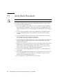
Handling Precautions
A fully configured rackmounted array system can weigh in excess of 1400 pounds
(627 kg). Any floor that this system will cross has to be able to withstand this load.
The rackmounted system is equipped with wheels for ease in installation, and
moveability of the system prior to installation. Use enough personnel when moving
the rack, especially on sloping loading docks and ramps to gain access to a raised
computer room floor. Move the rack slowly and deliberately, and make sure the floor
is free of foreign objects and cables that the rack could roll over.
Sun Microsystems suggests that all personnel moving the rack wear protective
footwear.
Install the rack on a level surface. At each corner, on the base of the rack, are
adjustable non-skid pads. These must be extended when the rack is installed to stop
the rack from rolling around. These pads are not to be used to level the rack.
The array weighs 67 pounds (30 kg). Use two people to lift the array to avoid injury.
Choose a table or flat surface that can adequately support the arrays.
2.2
Safety Precautions
For your protection, observe the following safety precautions when setting up your
equipment:
2.2.1
■
Follow all cautions and instructions marked on the equipment.
■
Ensure that the voltage and frequency of your power source match the voltage
and frequency inscribed on the equipment’s electrical rating label.
■
Never push objects of any kind through openings in the equipment. Dangerous
voltages may be present. Conductive foreign objects could produce a short
circuit that could cause fire, electric shock, or damage to your equipment.
Power Safety
■
2-2
Sun products are designed to work with single phase power systems having a
grounded neutral conductor. To reduce the risk of electric shock, do not plug
Sun products into any other type of power system. Contact your facilities
manager or a qualified electrician if you are not sure what type of power is
supplied to your building.
Sun StorEdge T3 and T3+ Array Site Preparation Guide • August 2001
2.3
■
Your Sun product is shipped with a grounding type (three-wire) power cord.
To reduce the risk of electric shock, always plug the cord into a grounded
power outlet.
■
Not all power cords have the same current ratings. Household extension cords
do not have overload protection and are not meant for use with computer
systems. Do not use household extension cords with your Sun product.
Placement of a Sun Product
Do not block or cover the openings of your Sun product. Never place a Sun product
near a radiator or heat register. Failure to follow these guidelines can cause
overheating and affect the reliability of your Sun product.
2.4
Laser Compliance Notice
Sun products that use laser technology comply with Class-1 laser requirements.
Refer to the Sun StorEdge T3 and T3+ Array Regulatory and Safety Compliance Manual
for this notice.
Chapter 2
Local Facility Safety
2-3
2-4
Sun StorEdge T3 and T3+ Array Site Preparation Guide • August 2001
CHAPTER
3
Facility Requirements
This chapter describes facilities requirements for the Sun StorEdge T3 and T3+ array,
and includes the following sections:
■
“Environmental Specifications” on page 3-2
■
“Electrical and Power Specifications” on page 3-3
■
“Physical Specifications” on page 3-5
3-1
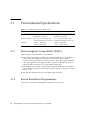
3.1
Environmental Specifications
TABLE 3-1
3.1.1
Facility Environmental Specifications
Specifications
Operating
Nonoperating
Temperature
10˚ to 35˚C with maximum
gradient 20˚C per hour
-40˚ to 70˚C with maximum
gradient 20˚C per hour
Relative humidity
20 to 80% noncondensing with
maximum gradient 10% per hour
5 to 95% noncondensing with
maximum gradient 10% per hour
Altitude
-1,000 to +10,000 feet
(-305 to +3,048 meters)
-1,000 to +40,000 feet
(-305 to +12,192 meters)
Electromagnetic Compatibility (EMC)
The following is recommended for all installations:
3.1.2
■
All AC mains and supply conductors to power distribution boxes for both the
rack system and the desktop system must be enclosed in metal conduit or
raceway, when specified by local, national, and/or other applicable government
codes and regulations. The supply conductors and power distribution boxes (or
equivalent metal enclosure) are to be grounded at both ends.
■
The supplied arrays require voltages within minimum fluctuation. The facilities
voltage supplied by the customer/end user must maintain a voltage of not more
than (+/-) 5%.
■
The customer facilities shall provide suitable surge protection.
Secure Installation Requirements
This section contains the requirements for placement of the array(s).
3-2
Sun StorEdge T3 and T3+ Array Site Preparation Guide • August 2001
3.1.2.1
Placement of Rackmounted Systems
The array rackmounted configuration can exceed 1400 pounds (627 kg).
The floor surface must be level. The rack is equipped with wheels, for ease in
installation, and moveability of the system prior to installation. At each corner, on
the base of the rack, are adjustable non-skid pads. These must be extended when the
rack is installed to stop the rack from rolling around. These pads are not to be used
to level the rack.
To minimize personal injury in the event of a seismic occurrence, Sun Microsystems
suggest that the rack be securely fastened to a rigid structure extending from the
floor to the ceiling or from the walls of the room in which the rack is located.
3.1.2.2
Placement of Individual Tabletop Units
The array weighs 67 pounds (30 kg). The array enterprise configuration weighs 135
pounds (60 kg).
Choose a table or flat surface that can adequately support the array. Do not place
more than two arrays on a table, unless the table is rated to support the combined
weight of the arrays designated to be installed, and the table is securely fastened to
the wall or a rigid structure extending from the ceiling to the floor.
Do not stack more than two arrays. If the tabletop configuration is a greater number
than two arrays, place the arrays side by side in stacks of two or one.
Do not place the arrays on the edge of the table. Set the array so that at least 50% of
the it is inside the table or desk leg support area. Failure to do this may cause the
table or desk to tip over.
3.2
Electrical and Power Specifications
This section contains electrical requirements for rackmounted and table top arrays.
3.2.1
Sun StorEdge T3 and T3+ Array
Rackmounted Systems
All Sun StorEdge T3 and T3+ arrays require two independent power sources. Each
array rack has two power conditioners (distribution), for redundancy, mounted in
the base of the rack. Each array has two power and cooling units, and each power
Chapter 3
Facility Requirements
3-3
and cooling unit on the array connects to a different conditioner. To maintain the
power redundancy, each conditioner must be connected to independent power
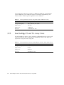
sources. TABLE 3-2 lists the power required for each conditioner.
TABLE 3-2
3.2.2
Power Specifications for the Array Rack (Each Conditioner Source)
Specification
Rating
Voltage and frequency
200 to 240 VAC, 47 to 63 Hz
Input current
20A max
Input power
3,600W max
Heat load
12,320 BTUs/hr. max
Sun StorEdge T3 and T3+ Array Units
All Sun StorEdge T3 and T3+ arrays require two independent power sources. Each
array has two power and cooling units for redundancy. TABLE 3-3 lists the power
required for each power and cooling unit.
TABLE 3-3
3-4
Power Specifications for the Sun StorEdge T3 and T3+ Array (Each Source)
Specification
Rating
Voltage and frequency
100 to 240 VAC, 47 to 63 Hz
Input current
5A max
Input power
450W max
Heat load
1,540 BTUs/hr. max
Sun StorEdge T3 and T3+ Array Site Preparation Guide • August 2001
3.3
Physical Specifications
This section contains the physical requirements for array systems.
3.3.1
Sun StorEdge T3 and T3+ Array
Rackmounted Systems
3.3.1.1
Installation Clearances
For FRU removal and replacement:
3.3.1.2
■
The rack has a front door that is 24 inches (61 cm) wide. This is the required front
clearance.
■
The rack has a back door that is 21 inches (53 cm) wide. This is the required back
clearance.
Cooling Clearances
For cooling:
■
The rack has a front door that is 24 inches (61 cm) wide. This is the required front
clearance.
■
The rack has a back door that is 21 inches (53 cm) wide. This is the required back
clearance.
■
No cooling clearance is required on the sides of the rack.
Chapter 3
Facility Requirements
3-5
3.3.1.3
Physical Dimensions
TABLE 3-4
Sun StorEdge T3 and T3+ Array Racks
Height
Width
Depth
Weight
74 inches
24 inches
36.5 inches
1,400 lbs
188 cm
61 cm
93 cm
627 kg
3.3.2
Sun StorEdge T3 and T3+ Array Units
3.3.2.1
Installation Clearances
For FRU removal and replacement, 15 inches (37 cm) is required front and back.
3.3.2.2
Cooling Clearances
For cooling, 6 inches (15 cm) is required front and back. No cooling clearance is
required on the sides or the top and bottom of the array.
3.3.2.3
Physical Dimensions
TABLE 3-5
3-6
Sun StorEdge T3 and T3+ Array Units
Height
Width
Depth
Weight
5.25 inches
17.5 inches
18.5 inches
67 lbs
13.33 cm
44.45 cm
47 cm
30.4 kg
Sun StorEdge T3 and T3+ Array Site Preparation Guide • August 2001
CHAPTER
4
Unpacking the Array Rack
This chapter shows, in pictorial form, how a Sun StorEdge T3 and T3+ array rack is
packaged, and how to unpack it. This chapter also describes how much clearance is
needed to remove the outer packaging, and how to remove it from the shipping pallet.
Note – Make note of the clearances needed to remove the outer packaging.
All packaging for Sun products should be retained, so that it can be reused in the
event that the product needs to be moved or shipped to a subsequent location
during its life cycle.
4-1
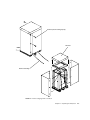
Height
Depth
Width
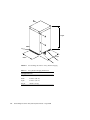
FIGURE 4-1
Sun StorEdge T3 and T3+ Array Rack Packaging
TABLE 4-1
Array Rack Packaging Dimensions
Packaging Dimensions
4-2
Height
80 inches (203 cm)
Width
43 inches (109 cm)
Depth
47 inches (119 cm)
Weight
1500 lbs (672 kg)
Sun StorEdge T3 and T3+ Array Site Preparation Guide • August 2001
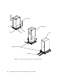
Remove plastic locking clips (6)
Lift lid off
Remove banding
FIGURE 4-2
Rack Packaging Removal Detail
Chapter 4
Unpacking the Array Rack
4-3
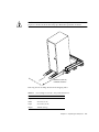
Ramps (2)
Saddle bag
Pallet
Rack
Ramp position guide
Ramps
FIGURE 4-3
4-4
Removing the Saddle Bag and Positioning the Ramps
Sun StorEdge T3 and T3+ Array Site Preparation Guide • August 2001
Caution – Take care when removing the rack from the pallet. Use two or more
people to roll the rack down the ramps provided. Wear protective footwear.
e
nc
ra
lea
C
100 inches (254 cm)
minimum clearance
Removing the Sun StorEdge Rack From the Shipping Pallet
TABLE 4-2
Sun StorEdge T3 and T3+ Array Rack Dimensions
Rack Dimensions
Height
74 inches (188 cm)
Width
24 inches (61 cm)
Depth
36.5 inches (93 cm)
Weight
1400 lbs (627 kg)
Chapter 4
Unpacking the Array Rack
4-5
4-6
Sun StorEdge T3 and T3+ Array Site Preparation Guide • August 2001
CHAPTER
5
Array Rack and Tabletop
Installation Requirements
This chapter describes installation requirements for installing Sun StorEdge T3 and
T3+ arrays in a rack or on a tabletop, and includes the following sections:
■
“Array Rack Placement” on page 5-2
■
“Tabletop Placement” on page 5-3
■
“Cable Specifications” on page 5-4
5-1
5.1
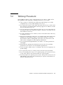
Array Rack Placement
Caution – The array rackmounted configuration can exceed 1400 pounds (627 kg).
Follow these guidelines when preparing a rackmount placement for your system.
5-2
■
The floor surface must be level.
■
The rack is equipped with wheels, for ease in installation and moveability of
the system prior to installation. Move the rack slowly and deliberately, and
make sure the floor is free of foreign objects and cables that the rack could roll
over.
■
At each corner, on the base of the rack, are adjustable non-skid pads. These
must be extended when the rack is installed to stop the rack from rolling
around.
■
Leave enough space in front of the rack to access components for servicing.
The rack has a front door. The door is 24 inches
(61 cm) wide. This is the required front clearance.
■
Leave enough space in back of the rack to access components for servicing. The
rack has a back door. The back door is 21 inches (53 cm) wide. This is the
required back clearance.
■
Keep power and interface cables clear of foot traffic. Route cables inside walls,
under the floor, through the ceiling, or in protective channels or raceways.
Route interface cables (excluding fiber optic cables) away from motors and
other sources of magnetic or radio frequency interference.
■
Do not exceed cable length limitations. See TABLE 5-1 for cable specifications
and lengths.
■
The array rack requires two separate power sources. These power sources are
to be independent to each other, and each controlled by a separate circuit
breaker at the power distribution point.
■
Up to eight arrays can be installed in one array rack.
Sun StorEdge T3 and T3+ Array Site Preparation Guide • August 2001
5.2
Tabletop Placement
Sun StorEdge T3 and T3+ arrays can be placed to sit on a desk or a table. Follow
these guidelines when preparing a tabletop placement for your system.
■
Choose a desk or a table that can support 67 pounds (30 kg) for one fully
configured array or 135 pounds (60 kg) for two arrays.
■
Do not place the array(s) on the edge of the table. Set the array so that at least
50% of the array is inside the table or desk leg support area. Failure to do this
may cause the table to tip over.
■
Leave enough space in front and in back of the array to access components for
servicing. To remove the components requires a clearance of 15 inches (37 cm)
front and back of the array.
■
Provide a minimum space of 6 inches (15 cm) in front and in back of the array
for adequate air flow.
■
Keep power and interface cables clear of foot traffic. Route cables inside walls,
under the floor, through the ceiling, or in protective channels or raceways.
Route interface cables (excluding fiber optic cables) away from motors and
other sources of magnetic or radio frequency interference.
■
Do not exceed cable length limitations. See TABLE 5-1 for cable specifications
and lengths.
■
Ensure that the operating environment for the array does not exceed the
specifications. See TABLE 3-1 for environmental specifications.
■
Use two people to lift the array to avoid injury. The array can weigh up to 67
pounds (30 kg).
■
Do not place the array in a vertical position. Place the array horizontally.
■
If you are installing two arrays, as in a partner group, you can stack one array
on top of the other. Do not stack more than two arrays together.
■
The array requires two separate power sources. These power sources are to be
independent to each other, and controlled by two separate circuit breakers at
the power distribution point.
Chapter 5
Array Rack and Tabletop Installation Requirements
5-3
5.3
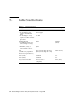
Cable Specifications
TABLE 5-1
Cable Specifications
Cable Type
Host interface (FC-AL):
• Sun StorEdge T3 array
requires copper adapter
(MIA)
• Sun StorEdge T3+ array
requires LC-SFF to SC fiberoptic cable
5-4
Connector
Maximum Length
82.021 ft (25 m)
DB-9 copper
LC-SFF
Shielded Ethernet:
• 10/100BASE-T, category 5
(Sun StorEdge T3+ array)
RJ-45
• 10BASE-T, category 3
(Sun StorEdge T3 array)
RJ-45
Serial
(Available only to qualified
field service representatives.)
RJ-11 (Sun StorEdge T3 array)
RJ-45 (Sun StorEdge T3+ array)
82.021 ft (25 m)
Power (110V)
Standard
n/a
Power (220V)
Standard
n/a
Array interconnect cable
DB-9 (not FC-AL
compliant)
24 in. (61 cm)
Sun StorEdge T3 and T3+ Array Site Preparation Guide • August 2001
328.084 ft
(100 m)
APPENDIX
A
Cabinet and Rack Requirements
This appendix contains requirements for installing a Sun StorEdge T3 and T3+ array
in standard 19-inch Electronics Industries Association/Radio Electronics Television
Manufacturers Association (EIA/RETMA) cabinets or racks. The array is designed to
be compatible with Sun and other standard 19-inch EIA/RETMA cabinets or racks.
However, you must make sure the cabinet or rack you are using meets the
requirements in this chapter before installing and operating the array.
The information in this appendix includes:
■
“Cabinet and Rack Hardware” on page A-2
■
“Specifications” on page A-6
■
“Product Servicing” on page A-7
■
“SunService Policy on Third-Party Products” on page A-8
A-1
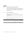
A.1
Cabinet and Rack Hardware
A cabinet is a freestanding and self-supporting enclosure for housing electrical and
electronic equipment. It is usually fitted with doors and side panels, which may or
may not be removable. A rack is an open structure for mounting electrical and
electronic equipment. This section describes features of cabinets and racks that can
be used to hold an array.
A.1.1
Physical Dimensions
There are two types of mounting kits available for the array:
■
Rackmount hardware that can be adapted to install the array in standard 19-inch
EIA/RETMA cabinets.
■
Rackmount hardware for mounting arrays in standard 19-inch EIA/RETMA
racks.
To use one of these kits, the rack or cabinet must meet the criteria listed in TABLE A-1.
TABLE A-1
Cabinet and Rack Dimensions
Measurement
Cabinet
Rack
Depth (the distance between the front and back flanges)
30 to 34 in.
76.2 cm to 86.4 cm
3 in. or 6 in.
7.6 cm to 15.2 cm
Mounting hole pitch (the width between the mounting holes)
18.3 in.1
46.5 cm
18.3 in.1
46.5 cm
1. This is an industry standard dimension and confirms that the structure is a 19-inch cabinet or rack.
A-2
Sun StorEdge T3 and T3+ Array Site Preparation Guide • August 2001
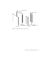
Depth (30–34 in.)
Depth (3 or 6 in.)
Mounting
hole pitch (18.3 in.)
Cabinet
FIGURE A-1
Mounting
hole pitch (18.3 in.)
Rack
Cabinet and Rack Physical Measurements
Appendix A
Cabinet and Rack Requirements
A-3
Also, the mounting flanges must contain the industry standard repeating hole
pattern shown:
Mounting hole pitch
.625 in.
.625 in.
.50 in.
.625 in.
.625 in.
.50 in.
.625 in.
.625 in.
.50 in.
FIGURE A-2
A.1.2
Industry Standard Repeating Hole Pattern
Vertical Mounting Space
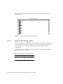
Vertical mounting space is defined in rack units (RUs). One rack unit is equivalent to
1.75 inches (4.4 cm) of vertical mounting space, or three mounting holes. Subsystems
such as the array are usually specified as requiring some number or RUs of
mounting space.
To install the array in a cabinet or rack, the cabinet or rack must support the RU
measurements listed in TABLE A-2.
TABLE A-2
A-4
Mounting Kit RU Measurement
Number of Arrays
Cabinet
Rack
One
4 RUs
Not available
Two
7 RUs
7 RUs
Sun StorEdge T3 and T3+ Array Site Preparation Guide • August 2001
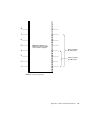
8
7
6
5
Note: RU boundaries are
between the holes spaced
closer (0.50 in.) together
Space occupied
by 7-RU arrays
4
3
Space occupied
by 4-RU arrays
2
1
FIGURE A-3
Rack Unit Spacing
Appendix A
Cabinet and Rack Requirements
A-5
A.2
Specifications
To use the Sun StorEdge T3 and T3+ array in a standard 19-inch EIA/RETMA
cabinet or rack, the environment must meet the specifications outlined in this
section, along with those listed in the Sun StorEdge T3 and T3+ Array Installation,
Operation, and Service Manual.
Note – For power system redundancy, you must use two separate connectors
supplied by two different power sources (the power requirements listed are for each
connector).
TABLE A-3
Power Specifications
Specifications
Rating
Voltage and frequency
100 to 240 VAC, 47 to 63 Hz
Input current
5A max
Input power
450W
Heat load
1,540 BTUs/hr max
TABLE A-4
Environmental Specifications
Specifications
Operating
Nonoperating
Notes
Temperature
5˚ to 35˚C with
maximum gradient
20˚C per hour
-40˚ to 70˚C with
maximum gradient
20˚C per hour
This measurement is for air entering the
unit through the front panel.
Ventilation
25 in.2 (63.5 cm2) in
front open area
Unrestricted airflow through front and
back cabinet doors (if present) is
required for each array.
25 in.2 (63.5 cm2) in
back open area
Relative humidity
A-6
20 to 80%
noncondensing with
maximum gradient
10% per hour
Maintain proper exhaust ventilation by
ensuring that there are no physical
restrictions to airflow at the back of the
cabinet.
5 to 95%
noncondensing with
maximum gradient
10% per hour
Sun StorEdge T3 and T3+ Array Site Preparation Guide • August 2001
TABLE A-4
Environmental Specifications (Continued)
Specifications
Operating
Nonoperating
Notes
Effective altitude
(from drive
specification)
–1,000 to +10,000 ft
(-305 to +3,048 m)
-1,000 to +40,000 ft
(-305 to +12,192 m)
Shock (from drive
specification)
4.0G for maximum
duration of 11 ms
(half sinewave)
15G for maximum
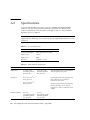
duration of 11 ms
(half sinewave)
Shock can be applied from any axis
X,Y, or Z.
Vibration (from
drive specification)
5 to 500 Hz @ 0.25G
(swept sinewave)
5 to 500 Hz @ 1.0G
(swept sinewave)
Vibration can be applied from any axis
X,Y, or Z.
The cabinet or rack must not exert any
excessive shock or vibration to the
product that could interfere with
proper operation.
A.3
Product Servicing
To allow room for service, the array must be installed in a rack or cabinet such that:
■
The front and back LED status indicators are visible.
■
Cables and connections are accessible and are not subject to stress from adjacent
panels or closed doors.
■
Field-replaceable units (FRUs) are accessible for servicing and replacement.
See “Array Rack Placement” on page 5-2 and “Tabletop Placement” on page 5-3 for
guidelines on product placement.
Appendix A
Cabinet and Rack Requirements
A-7
A.4
SunService Policy on Third-Party
Products
Sun Microsystems, Inc. and its affiliates (Sun), provide product warranties only for
products listed on Sun Network Storage Product Group’s price list (Sun Products).
It is the policy of the SunServiceSM group to provide a warranty for all Sun Products
pursuant to the terms set forth in the original purchase agreement. Sun does not
provide any warranties, implied or express, on products purchased by customers
from third-party vendors and installed on Sun Products.
Customers can install third-party products without voiding Sun’s warranty
accompanying the Sun Products. Installation of third-party products, however, may
void certain regulatory certifications.
Service calls that originate as a result of the failure of a third-party product, or any
damage to a Sun Product resulting from the installation or presence of a third-party
product, will be billed to the Customer at Sun’s then-current time and materials
rates.
A-8
Sun StorEdge T3 and T3+ Array Site Preparation Guide • August 2001
APPENDIX
B
Preinstallation Worksheet
This appendix provides a worksheet for gathering and recording the information
required to successfully install a Sun StorEdge T3 and T3+ array. It includes the
following sections:
Use this worksheet to preplan the data, Ethernet, and TFTP connections from the
application, management and TFTP host system(s). The application, management
and TFTP hosts can all reside on the same server.
Note – Root access is required for all hosts during installation.
B.1
■
“Host System Types” on page B-1
■
“Information Required Prior to Installation” on page B-2
Host System Types
TABLE B-1 lists the host system types supported by the Sun StorEdge T3 and T3+
array.
TABLE B-1
Host System Types
Application host
Utilizes the FC-AL Fibre Channel connection as a data path to and
from the array.
Management host
Administers configuration and health monitoring of the array
through a network connection.
TFTP host
Downloads bootcode to the array through a network connection.
B-1
B.2
Information Required Prior to
Installation
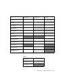
Use the preinstallation worksheet on the following page to record the information
you will need to install each array.
B-2
Sun StorEdge T3 and T3+ Array Site Preparation Guide • August 2001
Item
Management Host
Application Host
TFTP Host
Host ID
Host name
Host IP address
Gateway IP address
Array IP address
Array name
TFTP host address
OS/patch revision level
VERITAS DMP release
Primary application
StorTools™ release
Sun StorEdge Component
Manager release
Legend:
Required Field
Optional Field
Not Applicable
Appendix B
Preinstallation Worksheet
B-3
B-4
Sun StorEdge T3 and T3+ Array Site Preparation Guide • August 2001
Glossary
A
administrative
domain
alternate master
controller unit
Alternate Pathing
(AP)
Partner groups (interconnected controller units) that share common
administration through a master controller.
Also called “alternate master unit,” the secondary array unit in a partner group
that provides failover capability from the master controller unit.
A mechanism that reroutes data to the other array controller in a partner group
upon failure in the host data path. Alternate Pathing requires special software
to perform this function.
auto cache mode
The default cache mode for the Sun StorEdge T3 and T3+ array. In a fully
redundant configuration, cache is set to write-behind mode. In a nonredundant
configuration, cache is set to write-through mode. Read caching is always
performed.
auto disable
The Sun StorEdge T3 and T3+ array default that automatically disables a disk
drive that has failed.
B
buffering
Data that is being transferred between the host and the drives.
Glossary-1
C
command-line interface
(CLI)
controller unit
The interface between the Sun StorEdge T3 and T3+ array’s pSOS operating
system and the user in which the user types commands to administer the
array.
A Sun StorEdge T3 and T3+ array that includes a controller card. It can be use
as a standalone unit or configured with other Sun StorEdge T3 and T3+ arrays.
G
Dynamic Multi-Pathing
(DMP)
A VERITAS Volume Manager feature that provides an Alternate Pathing
mechanism for rerouting data in the event of a controller failover.
E
enterprise
configuration
erasable programmable
read-only memory
(EPROM)
expansion unit
Glossary-2
One or more partner groups (pair of interconnected controller units) in a
system configuration.
Memory stored on the controller card; useful for stable storage for long periods
without electricity while still allowing reprogramming.
A Sun StorEdge T3 and T3+ array without a controller card. It must be
connected to a controller unit to be operational.
Sun StorEdge T3 and T3+ Array Site Preparation Guide • August 2001
F
Fibre Channel
Arbitrated Loop
(FC-AL)
field-replaceable unit
(FRU)
FLASH memory device
(FMD)
A 100 Mbyte/s serial channel that enables connection of multiple devices (disk
drives and controllers).
A component that is easily removed and replaced by a field service engineer or
a system administrator.
A device on the controller card that stores EPROM firmware.
G
Gigabit Interface
Converter (GBIC)
gigabyte (GB or
Gbyte)
graphical user interface
(GUI)
An adapter used on an SBus card to convert fiber-optic signal to copper.
One gigabyte is equal to one billion bytes (1Χ109).
A software interface that enables configuration and administration of the Sun
StorEdge T3 and T3+ array using a graphic application.
H
host bus adapter
(HBA)
An adapter that resides on the host.
hot spare
A drive in a RAID 1 or RAID 5 configuration that contains no data and acts as
a standby in case another drive fails.
hot-swappable
The characteristic of a field-replaceable unit (FRU) to be removed and replaced
while the system remains powered on and operational.
Glossary-3
I
input/output operations
per second (IOPS)
interconnect cable
interconnect card
A performance measurement of the transaction rate.
An FC-AL cable with a unique switched-loop architecture that is used to
interconnect multiple Sun StorEdge T3 and T3+ arrays.
An array component that contains the interface circuitry and two connectors
for interconnecting multiple Sun StorEdge T3 and T3+ arrays.
L
LC
light-emitting diode
(LED)
logical unit number
(LUN)
An industry standard name used to describe a connector standard. The Sun
StorEdge T3+ array uses an LC-SFF connector for the host FC-AL connection.
A device that converts electrical energy into light that is used to display
activity.
One or more drives that can be grouped into a unit; also called a volume.
M
master controller unit
media access control
(MAC) address
media interface adapter
(MIA)
megabyte (MB or
Mbyte)
megabytes per second
(MB/s)
Glossary-4
Also called a “master unit,” the main controller unit in a partner-group
configuration.
A unique address that identifies a storage location or a device.
An adapter that converts fiber-optic light signals to copper.
One megabyte is equal to one million bytes (1Χ106).
A performance measurement of the sustained data transfer rate.
Sun StorEdge T3 and T3+ Array Site Preparation Guide • August 2001
multi-initiator
configuration
A supported array configuration that connects two hosts to one or more array
administrative domains through hub or switch connections.
P
parity
Additional information stored with data on a disk that enables the controller to
rebuild data after a drive failure.
partner group
A pair of interconnected controller units. Expansion units interconnected to the
pair of controller units can also be part of the partner group.
power and cooling unit
(PCU)
pSOS
A FRU component in the Sun StorEdge T3 and T3+ array. It contains a power
supply, cooling fans, and an integrated UPS battery. There are two power and
cooling units in a Sun StorEdge T3 and T3+ array.
An operating system built into the Sun StorEdge T3 and T3+ array RAID
Controller firmware, which provides interfaces between the mounted RAID
volumes and the database environment.
Q
quiesce
To halt all drive activity.
R
read caching
redundant array of
independent disks
(RAID)
reliability, availability,
serviceability (RAS)
Data for future retrieval, to reduce disk I/O as much as possible.
A configuration in which multiple drives are combined into a single virtual
drive to improve performance and reliability.
A term to describe product features that include high availability, easily
serviced components, and very dependable.
Glossary-5
reverse address
resolution protocol
(RARP)
A utility in the Solaris operating environment that enables automatic
assignment of the array IP address from the host.
S
SC
Simple Network
Management Protocol
(SNMP)
small form factor
(SFF)
synchronous dynamic
random access memory
(SDRAM)
system area
An industry standard name used to describe a connector standard.
A network management protocol designed to give a user the capability to
remotely manage a computer network.
An industry standard describing a type of connector. An LC-SFF connector is
used for the host FC-AL connection to the Sun StorEdge T3+ array.
A form of dynamic random access memory (DRAM) that can run at higher
clock speeds than conventional DRAM.
Located on the disk drive label, the space that contains configuration data, boot
firmware, and file-system information.
U
uninterruptable power
source (UPS)
A component within the power and cooling unit. It supplies power from a
battery in the case of an AC power failure.
V
volume
Glossary-6
Also called a logical unit or LUN, a volume is one or more drives that can be
grouped into a unit for data storage.
Sun StorEdge T3 and T3+ Array Site Preparation Guide • August 2001
W
workgroup
configuration
world wide name
(WWN)
write caching
A standalone array connected to a host system.
A number used to identify array volumes in both the array system and Solaris
environment.
Data used to build up stripes of data, eliminating the read-modify-write
overhead. Write caching improves performance for applications that are
writing to disk.
Glossary-7
Glossary-8
Sun StorEdge T3 and T3+ Array Site Preparation Guide • August 2001