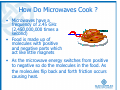
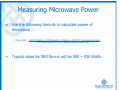
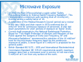
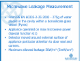
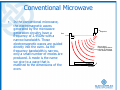
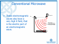
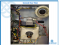
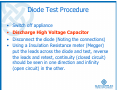
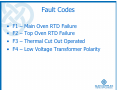
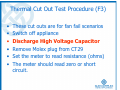
1
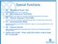
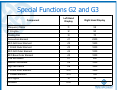
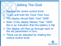
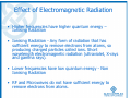
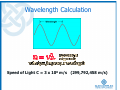
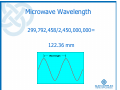
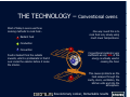
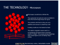
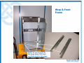
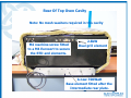
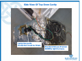
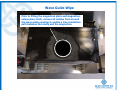
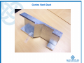
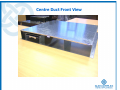
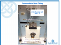
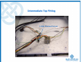
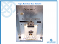
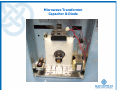
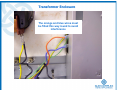
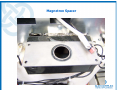
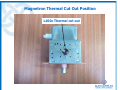
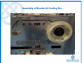
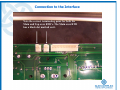
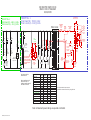
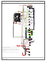
GENUS TRAINING
Genus Training
•
Operation of Genus
•
Microwaves
•
•
Genus Technology
Overview
•
Troubleshooting
•
Safety
•
•
•
•
•
•
•
•
•
•
•
User Manual
Special Functions
What and How ?
Measuring Microwave Power
Leakage Measurement
Differences
Mechanical Build
Wiring and Circuit Diagrams
Flowchart
Component Check
Do’s and Don’ts
Operation of Genus
THE TECHNOLOGY Top oven / grill
functions:
Conventional
Base heat
Full grill
Half grill
Intuitive rotary control:
Main oven
functions:
Genus mode
Multifunction (16
interactive modes)
Defrost
Press / turn 360o
On/Off
Lights only mode (push and hold)
Factory set clock
Programme (both ovens)
Time setting
Temp adjust before & during
cooking
Volume control
Revolutionary cooker, Remarkable results
Special Functions
• To access special functions depress the
centre control knob. All available icons
will illuminate in red.
• G functions 1-8 can be activated for
special functions by touching and holding
the numbered icon for 5 seconds.
Special Functions
• G1 – Microwave Power Test
Runs Microwave power for 170 seconds
• G2 – Auto Sequence Test Mode
Runs through each relay/triac operation and displays expected power output
• G3 – Manual Sequence Test Mode
As above but can be switched manually through each one using rotary control knob
• G7 – Demonstration Mode
Appliance operates as normal but switches no relays on. Can be operated from a 13A
Plug (3A Fuse)
• G8 – Volume Control
Will operate audible tone and allow the volume to be changed using the
rotary control.
• Lights only mode – Press and hold centre control knob
for 10 seconds.
Special Functions G2 and G3
Left Hand
Display
Right Hand Display
Frequency Stirrer
t1
58
T O Lights
t2
50
Cooling Fan
t3
70
Convection Element
rl1
2300
M O Grill Inner Element
rl2
1800
T O Grill Outer Element
rl3
1000
M O Grill Outer Element
rl4
1000
M O Base Outer Element
rl5
1000
Low Microwave
rl7
540
Medium Microwave
rl8
1000
High Microwave
rl9
1600
T O Grill Inner Element
rl12
1800
T O Base Element
rl15
765
t4
20
Component
M O Lights
Software
4-00
Setting The Clock
•
•
•
•
Depress the centre control knob
Touch and hold the ‘Cook Time’ Icon
The display should flash ‘Year’ ‘2005’
Note: If the display flashes ‘Year’ ‘2000’
this is an indication that the battery is flat
• The display will then go through each of
the set parameters in turn.
• These can be adjusted by rotating the
central control knob
Setting The Clock
•
•
•
•
•
•
•
The display will show the following:‘YEAR’ – Set Year
‘Cal’ – Set Month
‘Day’ – Set day of week (00 – Sunday)
‘Date’ – Set Date
‘Hour’ – Set Hour
‘Blank’ – Set Minute
Microwaves
What are they and How do they cook?
What are Microwaves
• Electromagnetic Radiation
• Energy rays that are either reflected or
emitted as radiation by objects. X-rays,
ultraviolet light, visible light, near-infrared
light, and heat (thermal) radiation are
different wavelengths of electromagnetic
energy.
Electromagnetic Spectrum
Conduct through free air
Effect of Electromagnetic Radiation
• Higher frequencies have higher quantum energy –
Ionising Radiation
• Ionising Radiation - Any form of radiation that has
sufficient energy to remove electrons from atoms, so
producing charged particles called ions. Short
wavelength electromagnetic radiation (ultraviolet, X-rays
and gamma rays).
• Lower frequencies have low quantum energy - Non
Ionising Radiation
• RF and Microwaves do not have sufficient energy to
remove electrons from atoms.
Wavelength Calculation
Speed of Light C = 3 x 10⁸ m/s (299,792,458 m/s)
Wavelengths
Microwave Wavelength
299,792,458/2,450,000,000=
122.36 mm
Electromagnetic Radiation
• E Field- This is the electric part of the wave. It causes arcing in
metallic objects and causes intense hot spots in the cavity and is
suppressed. It is measured in volts
• H Field- This is the magnetic part of the wave. It does not cause
arcing and distributes the energy more evenly around the cavity,
creating fewer hot spots. It is enhanced in the cavity.
Electromagnetic Radiation
Wavelength
•
Wavelength. This is the distance from one point in the wave to the
same point on the next wave. A peak to a peak, or trough to a
trough or any point in between. It is a measure of the ‘size’ of the
wave. The shorter the wavelength, the smaller the objects it
affects.
Electromagnetic Radiation
•
•
Frequency.
This is the number of complete
waves that pass a specified, fixed
point in one second. The
frequency of microwaves is
2.45GHz. That means that
2,450,000,000 waves pass a
specified, fixed point in one
second.
•
Because the speed of
electromagnetic waves is set at 3
million metres per second, and
the speed of a wave is the
frequency multiplied by the
wavelength, if the frequency of
an electromagnetic wave
changes, so must the
wavelength.
Electromagnetic Radiation
•
•
•
Amplitude.
This is the vertical
distance from the top of
one peak of a wave to
the bottom of a trough.
It is a measure of the
energy in a wave.
A wave with a large
amplitude has a larger
energy than a wave with
a smaller amplitude.
Electromagnetic Radiation
•
•
•
Node.
In a standing wave, the
area of minimum
displacement is called a
Node. This is where the
two waves interfere with
each other to produce an
area of no displacement.
That is, the amplitude is
zero.
At these points there is
no heating effect.
Electromagnetic Radiation
•
•
•
Antinode.
This it the opposite of a
node. This is where the
two waves interfere with
each other to produce an
area of maximum
displacement, one that is
twice the amplitude of
one wave on its own.
This is an area of
maximum heating effect.
Electromagnetic Radiation
•
•
•
•
Modes.
Imperfectly Matched, not a mode
A mode is a wave that is
perfectly matched to the
space it inhabits.
Thus a mode is a wave that
has become a standing wave,
and as such has node and
Perfectly matched, thus a mode
anti-nodes.
The more modes than can be
created in a cavity, the more
anti-nodes there will be and
as such the energy will be
distributed amongst more hot
spots, decreasing their
intensity.
Cavity
How Do Microwaves Cook ?
• Microwaves have a
frequency of 2.45 GHz
(2,450,000,000 times a
second)
• Food is made up of
molecules with positive
and negative parts which
act like little magnets
• As the microwave energy switches from positive
to negative so do the molecules in the food. As
the molecules flip back and forth friction occurs
causing heat.
Measuring Microwave Power
•
•
•
•
•
•
Using two microwave safe containers place 1 litre of
water in each (2 litres total)
Take the average temperature of the water in both
containers to 0.1°C (T1)
Place the shelf on level 6 (from bottom) and place the
jars in the centre of the shelf
Switch on the appliance and use Special Function G1
The appliance is automatically set to run for 170
seconds
When complete take the average temperature of the
water in both containers (T2)
Measuring Microwave Power
•
Use the following formula to calculate power of
microwave :Power (W) = 4.187(Joules) x 2000(Quantity of Water) x K(T2-T1 Temperature Rise)
167(Magnetron on time – allows 3 second warm up)
•
Typical value for 900 Genus will be 500 – 550 Watts
Microwave Power
• A number of factors will determine the
microwave power output :• The supply voltage.
• The metal to metal connections within the
cavity i.e good continuity between metal
parts will result in higher output power.
In particular those parts closest to the
launch system.
• Excessive leakage from around the cavity.
Electromagnetic leakage
•
Leakage is prevented from the cavity by:-
1. The cavity itself reflects the Electromagnetic
radiation.
2. Any point there is a possibility of leakage ie
through holes from RTD and Element
connections a metallic mesh washer is placed.
3. The door is sealed using an electromagnetic
leakage prevention system (choke)
Electromagnetic Leakage System
•
•
•
The system works by
‘shorting out’ electromagnetic
energy at the point of egress
from the appliance.
Fig 4 shows that zero power
will exist at a half a
wavelength away from an
imposed short circuit.
Physics state that, over a
frequency range of 2.4352.475 GHz, the half
wavelength dimension is 6062mm (average 61mm)
Electromagnetic Leakage System
• Fig. 1 Primary Choke
• Location 1 shows
the gap between the
cavity and the choke
ditch.
• The three lines are
61mm long and we
impose the required
short circuit condition
at location 1.
Electromagnetic Leakage System
•
•
•
Fig. 2. Secondary Choke
Location 3 shows a gap
between the cavity and the
outer shell. This gap also
needs to be a magnetic short
circuit so as to absorb any
microwaves that were not
absorbed by the primary
choke, due to manufacturing
tolerances.
The three lines are again
61mm long and using the
same condition of the bottom
of the choke ditch, we impose
the required short circuit
condition at location 3.
Electromagnetic Leakage System
• Fig 3 Choke 3
• Short circuits at
points 1 and 3 result
in a short circuit at
point 4.
Microwave Leakage Measurement
• The power density of microwaves is
determined my measuring the amount of
energy that flows through one square
centimetre in 1 second.
• For our purpose we will be measuring
values in mW/cm2 using an Apollo x 10
Microwave Monitor.
Microwave Leakage
• Microwaves disperse and dissipate very
quickly in the atmosphere
• The exposure to microwave drops by the
square of the distance you move away
• E.g. if you are exposed to 5mW/cm2 at
50mm and then move to 500mm (10x)
the exposure will drop by a factor of 100
0.05mW/cm2
Microwave Exposure
• Microwaves act by depositing energy within the
material and so far as the human body is
concerned, the difference between exposure to
infra-red frequencies (radiant heat) and
microwaves is that the former produces surface
heating while the later is absorbed within the
body tissue thus raising its bulk temperature.
Thermal damage has been shown to occur at
radiation intensifies of 100 mW/cm2 and above.
Microwave Exposure
•
•
•
•
In 1960 the Post Office published a guide called "Safety
Precautions relating to Intense Radio-Frequency Radiation". This
recommended a maximum safe working level of 10 mW/cm2,
thereby setting a safety factor of 10.
A committee of the Medical Research Council carried out a review
in the late 1960s and their report in 1970 confirmed the 10
mW/cm2 limit for continuous exposure of personnel. It also laid
down parameters for short periods of exposure at higher levels.
Current draft proposals by the National Radiological Protection
Board for "The Health Protection of Workers and Members of the
Public against the Dangers of Extra Low Frequency, RF and
Microwave Radiations" recommend the retention of the 10 mW/cm2
level for the microwave frequency band for the continuous
exposure of adults. A lower figure of 5 mW/cm2 is proposed for the
general public.
British Standard BS 5175 : 1976 and International Electrotechnical
Commission Standard IEC 335:25 requirements specify maximum
leakage rates from a microwave oven in service, of not more than
5 mW/cm2 at 5 cm from any surface of the oven.
Microwave Leakage Measurement
• From BS EN 60335-2-25:2002 - 275g of water
placed in the cavity within a borosilicate glass
vessel (Pyrex)
• Appliance operated on max microwave power
(Special function G1)
• Detector moved around external surface of
appliance particular attention to door seal and
corners.
• Maximum allowed leakage 50W/m2 (5mW/cm2)
Genus Technology
Conventional Microwave
•
In the conventional microwave,
the electromagnetic waves
generated by the microwave
generation circuitry have a
Door
frequency of 2.45GHz with a
narrow bandwidth. These
electromagnetic waves are guided
directly into the oven. As the
frequency bandwidth is narrow,
only a small number of modes are
produced. A mode is the name
we give to a wave that is
matched to the dimensions of the
oven.
Magnetron
Narrow band
Electromagnetic Waves
with High ‘E’ field giving
a low number of modes
Turntable
Conventional Microwave
• These electromagnetic
waves also have a
very high E field, that
is the electric part of
an electromagnetic
wave.
Magnetron
Door
Narrow band
Electromagnetic Waves
with High ‘E’ field giving
a low number of modes
Turntable
Conventional Microwave
•
Some of the problems associated with conventional microwaves are:
1.
A small number of modes means a small number of intense hot spots.
Conventional microwaves usually incorporate a turntable to try and
improve the cooking performance by evening out the heating by rotating
the food through the hot spots. However it does not reduce the intensity
of these hot spots which damage the structure of many foods being
cooked.
2.
The high E field means that metal objects can cause arcing (sparking) in
the oven, making them very problematic to use.
3.
Launching the microwaves directly into the oven means that the quantity,
size, shape etc. of food substances changes the performance of the oven.
It also means that some types of food can deprive others of energy;
especially when some of the foods are frozen. Also, running the
microwave oven with nothing in the oven can damage the magnetron
through overheating.
4.
In many conventional microwave ovens it is not possible to vary the
amount of power produced by the microwave generation circuitry, instead
they have to pulse the power to achieve a similar, reduced effect,
however the damage caused by the hot spots is still the same.
Genus Oven
Magnetron
Separate, tuned
Cavity
Broadband Electromagnetic
Waves with High ‘H’ field
giving a high number of
modes
(Genus Waves)
Broadband
Electromagnetic
Waves with High
‘E’ field
Frequency Generator
• In Genus the electromagnetic waves are
launched into an innovative and patented,
separate tuned chamber that contains a
frequency stirrer.
Genus Oven
•
This gives Genus the following advantages:
1.
The frequency stirrer increases the bandwidth of the
electromagnetic field which means that the number of modes in the
oven are significantly increased, reducing the intensity of the hot
spots and eliminating the need for a turntable.
2.
The chamber is designed such that the electromagnetic waves
emitted from it have enhanced H field, that is the magnetic part of
the electromagnetic wave, and suppressed E field. This increases
the cooking performance and solves the problem of arcing between
metal surfaces.
3.
The separate chamber creates a constant load which means it is
possible to run Genus with nothing in the main oven without the
danger of overheating and damaging the magnetron. It also
means different types of food can be heated together without
affecting the overall cooking performance.
Genus Oven
• The electrical circuitry in Genus uses the
resistance of the heating elements to reduce the
power developed by the magnetron, meaning
the power levels can be reduced without
pulsing.
• Definition of the Genus wave is an
electromagnetic wave of frequency 2450MHz
with a broad bandwidth of +/-40MHz having a
high 'H' field and a low 'E' field.
THE TECHNOLOGY –
Most of today’s ovens use three
cooking methods to cook food…
1
Radiant heat
2
Conduction
3
Convection
Conventional ovens
One way round this is to
cook food very slowly using
much lower temperatures.
1
Food is heated from the outside
inwards, which is problematic in that it
over-cooks the exterior before it cooks
the interior.
3
1
Conventional cooking is very
inefficient as only 5% of the
energy is actually used in
cooking the food.
This causes problems as the
heat escapes through the
cavity, doors, ventilation, the
kitchen units and into the
atmosphere.
Revolutionary cooker, Remarkable results
THE TECHNOLOGY - Microwaves
Microwaves would look a bit like this
They generate hot spots & need a turntable to
drive the food through these hot spots
The problem with them is they are very
selective and uneven in what they cook
Cooking results are inconsistent at best
The electro-magnetic waves used in a
conventional microwave have a stronger
electric “E-Field”. This causes arcing (sparking)
with metal objects such as baking trays /
cutlery
Revolutionary cooker, Remarkable results
THE TECHNOLOGY
waves are different in two main
ways:
1 The Genus wave creates a myriad of tiny,
compact balls of energy. This enables the
food to be cooked in a more consistent way,
without the need for a turntable.
1
“H” Field
2
Genus suppresses the “E” field and amplifies
the “H” field. This improves the cooking
results and allows the use of metal dishes /
trays.
2
“E” Field
Revolutionary cooker, Remarkable results
THE TECHNOLOGY
•
-
How Genus works…
=
+
Conventional cooking
base & top heat
“Genus” wave
The most advanced domestic
oven in the World
Fanned
+ fanned heat
Genus therefore operates
automatically as a
multifunction oven, in Genus
mode (selecting the optimum
combinations for the best
possible cooking results)
Revolutionary cooker, Remarkable results
Magnetron
THE TECHNOLOGY -
Frequency Stirrer
This is an example of how we have
programmed Genus to product superb
cooking results
•
Fanned heat
Top heat
Base heat
Type
Genus (Full power)
Genus (Medium power)
Genus (Low power)
Time
Revolutionary cooker, Remarkable results
Algorithms
GENUS
Function
Default
Time
(Hours)
Default
Temperature
1
1.00
200
2
0.40
250
Short Warm
Maximum
Maximum
up Time
Conventional Genus Time Time Division Ratio
Correction
Time (Hours)
(Hours)
Long Warm
up Time
Correction
Fast
Warm
Elements (Any PWM over a 2 minute duty cycle) but still under
thermostatic control
Convection
Grill Inner
4.00
4.00
T/3
OFF
ON
OFF
Thermostatic
4.00
4.00
T/3
ON
OFF
OFF
Thermostatic
PWM 50%
0 - 29 mins
Thermostatic
30+ mins 50%
225
Grill Outer
Microwave Power
Base
High
Thermostatic Thermostatic
High for 4.5mins then Medium
4
0.40
5
2.00
>=*35mins 190
<*35mins 170
200
4.00
4.00
T/3
OFF
ON
OFF
Medium last 3 minutes of cooking
Thermostatic On
time
Thermostatic Thermostatic
for first 2 mins
Medium last 4 minutes of cooking
On for first
Thermostatic
for first 3
then on between 8
time
3.5 mins
mins then off
and 10 mins
Medium last 3 minutes of cooking
time
Low and then Medium for last 3
Thermostatic
minutes
Thermostatic
PWM 30%
High
6
2.00
180
4.00
4.00
T/3
ON
OFF
OFF
Thermostatic
7
0.45
200
4.00
4.00
T/3
OFF
ON
OFF
Thermostatic
8
0.30
150
4.00
4.00
T/3
ON
OFF
ON
Thermostatic
High
Defrost
Def
40 (fixed)
-
-
-
-
-
-
Thermostatic
Low 25% Duty Cycle
*0 - 45 mins T/3
3
1.00
170
4.00
4.00
ON
OFF
OFF
T/3
ON
OFF
OFF
*46 - 75 mins T/2.5
*76+ mins T/2.5
4.00
4.00
High 2.5mins then Low
Thermostatic
High
Mechanical Build
Wrap & Front
Frame
NOTE: Do not forget to fit
the hinge ducts, Left hand
and Right hand at this stage
Inside Top Oven Cavity
A standard 900E Stoves Premier
Cavity with a 2.8Kw Dual Grill
Element fitted.
Rear Of Top Oven Cavity
Note: No mesh washers required in this cavity
M4 machine screw fitted
to a M4 Eurosert to secure
the RTD and elements.
2.8kW
Dual grill element
A new 700Watt
Base element fitted after the
Intermediate rear plate.
Side View Of Top Oven Cavity
Lamp live parts
Protection must be fitted.
Standard Stoves Premier
600EMa light harness.
Wave Guide Wipe
Prior to fitting the magnetron plate and magnetron,
using emery cloth, remove all residue from around
the wave guide opening to enable a true conductive
path between the cavity and the magnetron.
Inside Of Main Oven Cavity
RTD
NOTE: Fit Mica shield
Into slot in launch box
Prior to fitting the match
Plate.
NOTE: Mesh washers
To be fitted on all element
tails and the RTD prior to
Securing them in the cavity.
Mica Fitting
Fit M5 Hexserts and use M5
Pozi pan screws to secure all
Elements and the RTD in the
Main oven cavity only.
Use 2 off screws to secure the
Mica strip to the launch box.
Main Oven Rear Insulation
Main Oven Wrap
Centre Vent Duct
Centre Duct Front View
Cavities and Centre Duct
Intermediate Rear Fitting
L70c thermal cut
out x 3
Intermediate Top Fitting
L100c Thermal Cut out
Top & Main Oven Base Elements
Microwave Transformer
Capacitor & Diode
Microwave Transformer Cap & Diode Wire
Connections
Transformer Enclosure
The orange and blue wires must
be fitted this way round to avoid
interference
Main Oven RTD
Magnetron Thermal Cut out Wiring
Magnetron Spacer
Magnetron Thermal Cut Out Position
L100c Thermal cut out
Assembly Of Magnetron
Assembly of Bracket & Cooling Fan
Connection to the Interface
Note the correct terminating point for both the
Main and Top oven RTD’s. The Main oven RTD
has a black dot marked on it.
Interface Earth Connection
General Rear View
Troubleshooting
Troubleshooting
• SAFETY FIRST
• Ensure the appliance is switched
off
• Whenever you remove the rear of
the appliance ALWAYS
DISCHARGE THE HIGH
VOLTAGE CAPACITOR
Troubleshooting
•
•
•
•
•
•
SAFETY FIRST-BE SAFE NOT SORRY
Use the available wiring and circuit diagrams.
Work in a logical and methodical manner.
If required use special function G3
Example flowchart 1 – No Display on Fascia
Example flowchart 2 – Poor Cooking
Performance
Discharging Capacitor
• Ensure appliance is switched off at the mains.
• Using discharge lead place the earth probe on
the chassis (ground), touch the other end of the
lead on one of the capacitor terminals leave for
a few seconds.
• Repeat with second terminal to chassis
• NOTE: The discharge lead should have a
nominal resistance of 270Ω which should be
checked on a regular basis
Capacitor Test Procedure
•
•
•
•
•
•
•
Switch off appliance
Discharge High Voltage Capacitor
Remove leads (Noting there position)
Put your meter on the highest Resistance ohm scale
Connect across the two capacitor terminals. The reading
should increase and then slowly decrease as the
capacitor is charged.
Reverse the leads and the effect should be repeated.
If you have a meter with a capacitor test feature use
this and the meter should read approx 1.2µF
Magnetron Test Procedure
•
•
•
•
Switch off appliance
Discharge High Voltage Capacitor
Disconnect plug from magnetron
Using the resistance reading on the meter
check across the two terminals of the
magnetron, this should read less than 1 ohm
• Check the reading from each terminal to the
magnetron casing, this should read infinity.
High Voltage Transformer Test
•
•
•
•
•
•
•
Switch off appliance
Discharge High Voltage Capacitor
Disconnect primary winding connections (Blue and
Orange), unplug from magnetron and remove leads
from capacitor (Noting lead connections)
Set meter to read resistance
Primary winding (6.3mm Male terminals) – Approx 2
ohms
Filament Coil (Leads on molex plug) – less than 1 ohm
High Voltage Secondary (Single red lead from
transformer with 6.3 receptacle to body of
transformer)– Approx 90 ohms (Note: Ensure insulation
on transformer body is cleared to obtain a true
reading.)
Diode Test Procedure
•
•
•
•
Switch off appliance
Discharge High Voltage Capacitor
Disconnect the diode (Noting the connections)
Using a Insulation Resistance meter (Megger)
put the leads across the diode and test, reverse
the leads and retest, continuity (closed circuit)
should be seen in one direction and infinity
(open circuit) in the other.
Fault Codes
•
•
•
•
F1
F2
F3
F4
–
–
–
–
Main Oven RTD Failure
Top Oven RTD Failure
Thermal Cut Out Operated
Low Voltage Transformer Polarity
RTD Test Procedure (F1, F2)
•
•
•
•
Switch off appliance at the mains
Disconnect the RTD
Set the meter to read resistance (ohms)
Check the resistance of the RTD by
placing the leads across the Molex plug.
• The resistance should read approximately
1000 ohms (1kohm)
• Note: The resistance should increase with
temperature.
Thermal Cut Out Test Procedure (F3)
•
•
•
•
•
•
These cut outs are for fan fail scenarios
Switch off appliance
Discharge High Voltage Capacitor
Remove Molex plug from CT29
Set the meter to read resistance (ohms)
The meter should read zero or short
circuit.
Low Voltage Transformer Test
• Switch off appliance
• Discharge High Voltage Capacitor
• Disconnect Low Voltage Transformer Molex
plug from CT15
• Set meter to read resistance (ohms)
• Primary Winding (Brown – Blue) – 30Ω
• Secondary Winding (Orange – Black) – 0.5Ω
Door Safety Circuit
Primary Door Switch
10A Fuse
Direction of Current
Monitor
Door Closed
Must open
before
primary
and
secondary
are closed
Secondary Door Switch
Door Safety Circuit
Failure of Primary and
Monitor
Monitor and Primary closed,
secondary open- Creates a
short circuit and blows the
fuse.
10A Fuse
Direction of Current
Monitor
Secondary Door Switch
Failure of Secondary
Primary open, monitor closed,
Secondary closed.
No current can flow
10A Fuse
No current can flow
Monitor
Secondary Door Switch
Door Safety Circuit
Primary Door Switch
10A Fuse
No Current
Door Open
Monitor
Secondary Door Switch
Door Safety Circuit Test
•
•
•
•
•
•
Switch off appliance at the mains
Discharge High Voltage Capacitor
Disconnect the door safety circuit from the power board
(remove CT19 and white lead from CT22)
With the meter set to read resistance you should get a
short circuit across these two connections when the
door is closed and an open circuit when the door is
open.
If an open circuit is detected the problem could be with
the door switch assembly or the magnetron thermal cut
out.
NOTE: If the fault is that the appliance is flashing door
when it is closed this could be due to the magnetron
thermal cut out, power board, ribbon cable or fascia
pcb.
Recommended Parts List
•
•
•
•
•
•
•
•
•
PCBA Fascia - 012550437
PCB Power Board - 082572700
Frequency Stir Blade - 0825665-00
Door Microswitch Assembly - 082575800
Low Voltage Transformer - 082573700
Main Oven Lamps - 082573200
Stir Motor - 0825700-00
2A Fuse (T250V)- Electronics
10A Fuse (250V) – Door Monitor
Safety
• Where possible switch off appliance before
starting work.
• WITH POWER OFF ALWAYS DISCHARGE
THE HIGH VOLTAGE CAPACITOR
• Leave yourself enough space to work around
the appliance.
• Check the leakage BEFORE and AFTER repairing
the appliance.
• Check the operation of the door safety switch
before leaving the appliance.
• Wear relevant PPE (Gloves etc)
REMEMBER
• Be safe not sorry
• Most work can be done with the appliance off
• If the anti tamper label has been removed
proceed with caution. Has somebody tampered
with the appliance!
• The ‘Low Voltage’ can be just as lethal as the
‘High Voltage’
• Check Leakage before leaving appliance
• Reapply anti tamper label to casing when work
is complete
Wiring & Circuit Diagrams
900 ELECTRIC RAPID COOK
ISSUE II CIRCUIT DIAGRAM
02/03/2005
PRIORITY No. 2
Total Power (W) - 4615 @ 240v
Total Current (A) - 15.1 @ 240v
PRIORITY No. 1
Total Power (W) - 7816 @ 240v
Total Current (A) - 32.6 @ 240v
WELLING TXMR
BWL - A01F - 03
Filter Circuit
K15
16Amp
Top
oven
Grill
outer
element
1000W
Top
oven
base
element
765W
Top Oven
Lights Filament
Type 2 x 25w
TOP OVEN
THERMAL
CUTOUT
100°C
16Amp
POWER
COOLING
FAN
58W
X1 100 nf
Capacitor 275volts
230v Transformer.
20 watts for the
lamps and 20watts
for driving the relays
and controling the
interface.
PROVISIONAL SWITCH
IDENTIFICATION:
K1
20Amp
MAIN OVEN
FREQUENCY
STIRRER 38W
Top
oven
Grill
inner
element
1800W
PANASONIC
MAGNETRON
2M 167
K 6 Triac
K18
Triac
BJB 77.914
MAIN OVEN
LIGHTS
2X10watts
each
RELAY POWER
OUTPUT (W)
K 1 - 20Amp
RED HIGHLITES INDICATE
MICROWAVE CIRCUIT.
GREEN HIGHLITES INDICATE
NON RELAY SWITCHES
K 2 - 20Amp
K 3 - 16Amp
K 4 - 16Amp
K 5 - 16Amp
K 6 Triac
K 7 - 16Amp
K 8 - 16Amp
K 9 - 20Amp
K10 - MOSFET Transitor
K11 - Triac
K 12 - 20Amp
K15 - 16Amp
K18 - Triac
Main
oven
convetor
element
2300W
K4
16Amp
Main
oven
grill
outer
1000W
K2
20Amp
Main
oven
grill
inner
1800W
230V
240V
256V
2110W
1655W
920W
920W
920W
53W
1655W
725W
1470W
18W
53W
1655W
700W
23W
2300W
1800W
1000W
1000W
1000W
38W
1800W
790W
1600W
20W
58W
1800W
765W
25W
2620W
2050W
1135W
1135W
1135W
66W
2050W
900W
1820W
23W
66W
2050W
870W
28W
K7 & K8
16Amp
Microwave
Medium
Main
oven
base
outer
1000W
K7 16Amp
Microwave
Low
DOOR
SWICTH
MONITOR
N.C.
MAIN
OVEN
THERMAL
CUTOUT
B
L70°C ?
16Amp
MAIN
OVEN
THERMAL
CUTOUT
A
L70°C ?
16Amp
K8
K5
16Amp
Main Oven
Base Element
1800 watts
DIODE
350mA
K7
K 9 - 20Amp
Microwave
High
1600W
SAFE WORKING
AT 256V
It is important that all components are
garanteed for at least 200.000 life cycles @ 256volts
Note: All element power ratings are quoted at 240volts
Mark Hope: Technical Centre
HV
CAPACITOR
1.2mF @
2100VOLTS
(rms)
with rapid
discharge
resistor
SECONDARY
DOOR
SWITCH
K10
MOSFET
Transitor
12volts
K3
16Amp
PRIMARY
DOOR
SWITCH
FUSE
10A
K11 Triac
K12
20Amp
MAGNETRON
THERMAL
CUTOUT
100°C
900E RAPID COOK MICROWAVE D.O.- Wiring Diagram:
ISSUE A
Brown 780mm
Brown 690mm
Brown 780mm
Brown 860mm
MAINS INLET
TERMINAL BLOCK
N
L
Black 620mm
TOP OVEN
GRILL ELEMENT
Green 580mm
Green 500mm
Black 470mm
Black 420mm
L100°C
16Amp
Thermal
Cutout
Yellow 580mm
Orange 960mm
Brown 510mm
Black 220mm
White 510mm
Orange 590mm
Black 110mm
T3
CT20
R1
T1
T2
R6
Green 800mm
FS1
CT1
CT3
CT4
TOP OVEN
BASE ELEMENT
K3
CT2
K12
CT5
K15
CT6
K1
R11
Red 370mm
C1
R5
R7
C4
CT18
R3
Q3
CT16
CT9
CT7
Brown 290mm
K4
CT23
R13
K2
Q5
White 470mm
CT13
R26
R24
R22
R23
R19
R25
R8
R21
R20
R9
R29
R12
IC1
L70°C
16Amp
Thermal
Cutout
C17
Q4
IC6
Black 120mm
Orange 300mm
K8
CT8
R10
Green 200mm
Black 900mm
IC3
IC5
IC4
CT17
MAIN OVEN
GRILL ELEMENT
R28
Green 930mm
IC2
Green 1000mm
Q2
D1
C2
CT10
D5
Red 290mm
R27
C12
D4
R2
K5
R15
C3
MAIN OVEN
CONVECTION FAN
ELEMENT
Green 120mm
Black 630mm
Brown 330mm
D2
R17
CT11
K7
Q1
R18
Black 120mm
R14
CT24
C11
Brown 860mm
L70°C
16Amp
Thermal
Cutout
FS2
R16
C13
CT19
C5
Brown 860mm
C8
L1
Blue 500mm
Black 620mm
C6
C7
CT29
CT14
D7
IC7
R4
D3
MAIN OVEN
BASE ELEMENT
D6
CT25
CT22
CT50
K9
CT15
CT150
CT21
Green 120mm
Blue 630mm
Orange 500mm
Black 920mm
White 1000mm
MAIN
APPLIANCE
COOLING FAN
Black 120mm
Blue 520mm
TRANSFORMER
Transformer
50
40 VA
VA 9v
Red 1360mm
Red 900mm
Terminal Block
for Cooling Fan
MAIN OVEN
FREQUENCY STIRRER
VIDAFLEX 500mm
Black 120mm
Black 470mm
Vidaflex
Sleeving
Orange 1000mm
Green 1000mm
Terminal Block
for Top Oven
Lights
Main Oven
Lights
120°C
16Amp
Thermal
Cutout
MAGNETRON
EARTH POINT
CHASSIS
Red 280mm
CAPACITOR
DIODE
ARRANGEMENT
Red 460mm
Blue 750mm
Red 1360mm
MICROWAVE
TRANSFORMER
Green 1000mm
Blue 500mm
L70°C
16Amp Fan Stall
Centre Duct
Thermal Cutout
Yellow 310mm
Red 450mm
DIODE
Red 900mm
Red 1220mm
Orange 500mm
Blue 500mm
Green 1000mm
White 1000mm
MICROWAVE
PRIMARY DOOR
SWITCH
NO
Brown 120mm
Unless otherwise specified, all cable on this harness where
the load (power in watts)
carry’s greater than 100Watts must be made from
Silicon Elastima and have a 1.0mm2 cross sectional area
It must also be capable of withstanding 16Amps plus 180°C
continuous.
If in doubt check power ratings of elements on page 8.
L70°C
16Amp Fan Stall
Intermediate Top Tray
Thermal Cutout
NC
MICROWAVE
DOOR SWITCH
MONITOR
NO
Brown 120mm
NC
MICROWAVE
SECONDARY DOOR
SWITCH
NO
Red 1220mm
Red 1360mm
NC
© This diagram is the property of Glen Dimplex Cooking Limited. Not to be reproduced or transmitted in any shape or form without the permission of Glen Dimplex Cooking Limited. 28/02/2005